Evolution of convex structure during counter-rotating electrochemical machining based on kinematic modeling
Wenjian CAO, Dengyong WANG,*, Zhiyuan REN, Di ZHU
a College of Mechanical and Electrical Engineering, Nanjing University of Aeronautics and Astronautics, Nanjing 210016, China
b Jiangsu Key Laboratory of Precision and Micro-Manufacturing Technology, Nanjing 210016, China
KEYWORDS Convex structure;Counter-rotating electrochemical machining;Current density;Equivalent kinematic model;Material removal
Abstract Counter-rotating electrochemical machining (CRECM) is a novel electrochemical machining (ECM) method, which can be used to machine convex structures with complex shapes on the outer surface of casings.In this study,the evolution of the convex structure during CRECM is studied.The complex motion form of CRECM is replaced by an equivalent kinematic model,in which the movement of the cathode tool is realized by matrix equations.The trajectory of the cathode tool center satisfies the Archimedes spiral equation, and the feed depth in adjacent cycles is a constant. The simulation results show that the variations of five quality indexes for the convex structure:as machining time increases,the height increases linearly,and the width reduces linearly,the fillets at the top and root fit the rational function, and the inclination angle of the convex satisfies the exponential function. The current density distributions with different rotation angles is investigated.Owing to the differential distribution of current density on workpiece surface,the convex is manufactured with the cathode window transferring into and out of the processing area.Experimental results agree very well with the simulation, which indicates that the proposed model is effective for prediction the evolution of the convex structure in CRECM.
1. Introduction
Electrochemical machining(ECM)is a non-contact machining method, during which the material is removed based on electrochemical anodic dissolution in neutral solutions (e.g. aqueous sodium nitrates).1,2Owing to the advantages such as no relevant tool wear, absence of residual stress and machining deformation,ECM has been widely used in aviation and aerospace applications.3,4However,the ECM process is quite complicated, in which the machining precision is affected not only by the trajectory of the cathode but also by the distribution of the interelectrode gap.5In order to effectively control the processing accuracy in ECM,the prediction of the final shape of a workpiece is an important issue to be studied.6,7Researchers around the globe have optimized the parameters in order to achieve desired anode profile corresponding to a specific tool geometry, and different simulation models have been proposed. Schaarschmidt, et al.8showed a simulation model of electrochemical precision machining with oscillating cathode.The machining accuracy could be improved by optimizing machining parameters. Zhitnikov, et al.9applied the methods of the theory of functions of a complex variable for investigation of the electrochemical machining process. The stepwise function of current efficiency was used to obtain the modeling of the precision process of ECM. Chen, et al.10introduced a simplified algorithm based on the quasi steady state shortcut(QSSSC) to simulate the changes of workpiece shape in pulse electrochemical machining. The shape of the cathode could be optimized to improve the machining accuracy. Jain and Gehlot,11solved 2-D Laplace equation in the interelectrode gap to determine the potential and flux distribution for the anode shape prediction in through-mask electrochemical micromachining (TM-ECMM). Algorithm was developed and implemented in MATLAB to estimate surface corrosion of anode workpiece for finite time steps.Liu,et al.12developed a model to simulate electrochemical micro-machining(EMM).By optimizing the tool structure and machining parameters,the shape accuracy and surface quality in EMM could be effectively improved.
Based on the literature survey, it is evident that simulation has played an important role in predicting the final shape of the anode workpiece and controlling precision of anode profile.However,the above literature is based on traditional sinking ECM, in which a pre-shaped cathode tool only linearly moves to complete the machining process. In this paper, the prediction of the evolution of the convex structure during counter-rotating electrochemical machining (CRECM) is focused. CRECM is a new electrochemical machining (ECM)method,which can be used to machine many convex structures with complex shapes on the outer surface of casings.13-15Fig.1 shows the principle of CRECM. The cathode tool and anode workpiece rotate at the same rotation speed in different directions, simultaneously, the cathode tool moves towards the anode workpiece at a constant feed rate. The cylindrical surface of the cathode tool has a window, whose interior is insulated. The anode material is dissolved rapidly, and the processed products are carried away by the high-feed electrolyte flowing through the machining area. The desired convex structures on the outer surface of anode workpiece can be obtained with time. In CRECM, electrodes movement are complex and special,which are quite different from traditional ECM.
In order to realistically simulate the movement process, a geometric motion model of the CRECM is simplified, and mathematical matrix equations for an equivalent kinematic model are established. According to the equivalent kinematic model,the real-time anodic shape evolution is obtained by displacing the boundary proportional to and in the direction of the local current density,and the variations of the current density on the surface of the convex structure are analyzed at different rotation angles. The evolutions of the convex structure at different machining times are obtained, and five quality indexes are used to evaluate the machining accuracy of the convex. A series of CRECM experiments are completed to compare simulation and experimental values. The results fit very well,which verifies the correctness of the proposed model.
2. Methods
2.1. Equivalent kinematic model
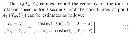
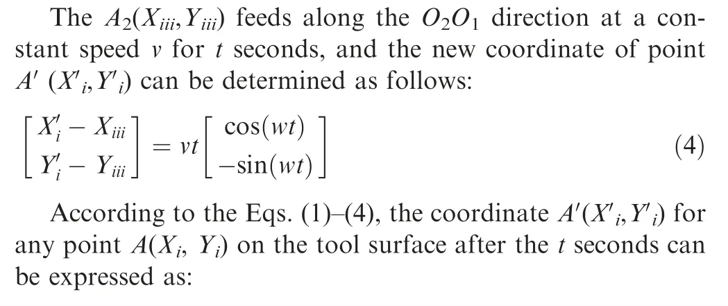
In CRECM process, the electrodes rotate and feed linearly,resulting in a complex form of motion, as shown in Fig. 1.In order to simplify the motion model of CRECM, the geometric movement of workpiece and tool are represented in a two-dimensional space as illustrated in Fig. 2. The workpiece is assumed to be stationary, and the cathode tool equivalent kinematic model is built for three steps16: (1) the revolution of the cathode tool around the center O1of the workpiece;(2) the rotation of the cathode tool around its own center O2; (3) the linear feed of the cathode tool towards the anode workpiece. In present study, the matrix equations of submotion are given, and an equivalent kinematic model is established.
Based on the equivalent kinematic model of CRECM, the coordinate A′X′i,Y′i) can be obtained for any point A(Xi,Yi)on the tool surface after the motion t seconds. The coordinate system is established with the center of the workpiece as the origin O1(0,0), and the starting coordinate of the center of the tool is O2(Xc,Yc).The equivalent kinematic model is classified into three steps:

Fig. 1 Principle of CRECM.

Fig. 2 Schematic diagram of equivalent kinematic model for CRECM.
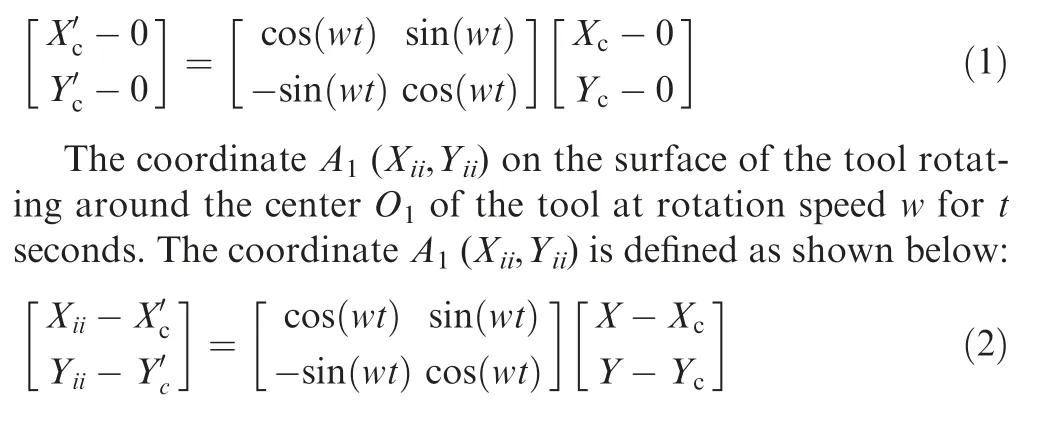
(1) The first step: revolution
The revolution of the tool around the center O1of the workpiece at rotation speed w for t seconds, and the coordinate O2(X′c, Y′c) of the tool center is determined as follows:
(2) The second step: rotation
(3) The third step: linear feed

2.2. Material removal model
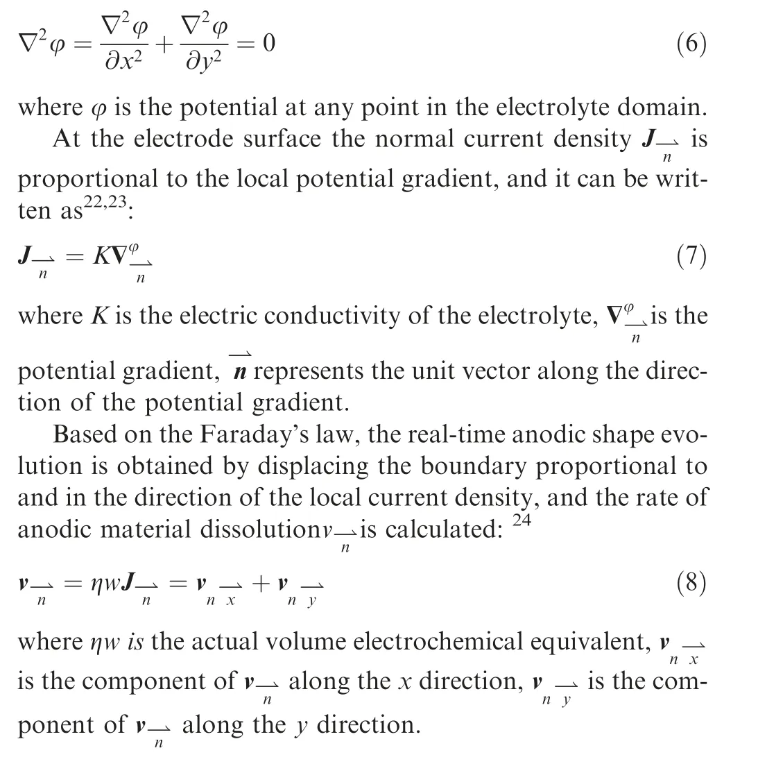
Based on Faraday’s law,17the material removal model for CRECM is proposed. For the simplification of the model, it can be considered that the bubble content is fixed, so the conductivity of the electrolyte is treated as a constant.18-20In addition, real-time anodic shape evolution can be achieved by controlling the movement of coordinate points on the anode surface, and the geometry of the convex structure can be predicted.
The electrode surfaces are regarded as equipotential surfaces, and the potential obeys Laplace equation21:
2.3. Preset conditions
According to the modeling of tool motion and the evolution process for the convex structure,necessary domain and boundaries for CRECM are built up, as shown in Fig. 3. A twodimensional simulation model includes an electrolyte domain Ω, anode boundary (Γ1), cathode boundaries (Γ2, Γ3, Γ4, Γ5),and tank boundary (Γ6). Γ6is the boundary of the inner wall of the electrolyte tank, as shown in Fig. 1. The movement of the cathode boundary conforms to Eq.(5),and the movement of Γ6satisfies the revolution equation around O1.
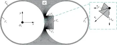
Fig. 3 Domain and boundaries for CRECM.
The applied voltage at the anode boundary (Γ1):

The cathode boundaries include arc boundary (Γ2) and window boundary (Γ3, Γ4, Γ5):

Based on the modeling of equivalent motion and material removal, the real-time anode boundary evolution can be obtained by displacing the boundary proportional to and in the direction of the local current density. The electrolyte domain is divided by a triangular mesh, which is refined in a small interelectrode gap. For all cases, simulation software(Ansys 19.0)is applied to calculate the evolution of the convex structure during CRECM.
3. Simulation results and discussion
3.1. Trajectory of the cathode tool
With the model of CRECM given above, the variation of the equivalent movement of the tool is obtained. The simulated parameters are particularly chosen: the applied voltage is 25 V, the tool feed rate is 0.08 mm/min, the initial interelectrode gap is 0.2 mm, the rotating speed is 0.5 r/min, the diameters of the workpiece and the tool are 50 mm. In Fig. 4, the trajectory of the center O2of the cathode tool in each cycle(T) is a spiral, and the tool feed depth in adjacent cycles is a constant (L), which can be determined as follows:

Based on the movement characteristics of the cathode tool,the trajectory of the center O2is isometric spiral, which satisfies the Archimedes spiral equation25:

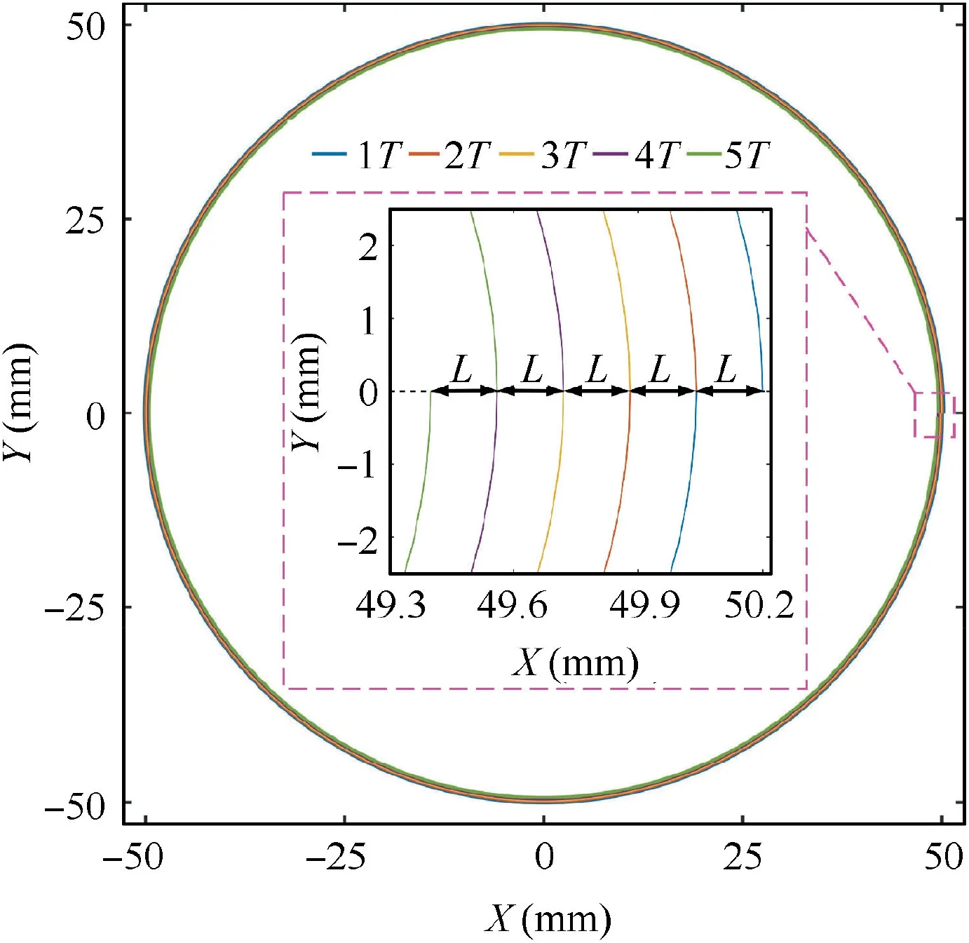
Fig. 4 Trajectory of center O1 of cathode tool for 5T.
3.2. Quality indexes for convex structure
Fig.5(a)shows the evolution of the convex structure at different machining times. As the machining time increases, the material is continuously dissolved under electrolysis, and the convex is getting slimmer and higher. In the same machining time, the amount (S) of material dissolved on the anode surface gradually decreases linearly, as shown in Fig. 5(b). This is because the tool feed depth in adjacent cycles is a constant in Section 3.1.Based on the characteristics of the convex structure, the machining accuracy of the convex structure can be evaluated from five quality indexes: the height H, the width D,the fillet RTat the top,the fillet RRat the root,and the inclination angles β of the sidewall, as shown in Fig. 6.
3.2.1. Height
As the cathode tool feeds at a constant speed, the height increases linearly in Fig. 7(a). Due to the stray corrosion, the height growth rate of the convex structure is less than the tool feed rate. Stray corrosion is caused by the existence of stray current during material electrochemical dissolution, and it plays an important role in affecting the machining accuracy.Fig. 7(b) shows the thickness of stray corrosion in the height direction increases linearly with the increase of machining time.
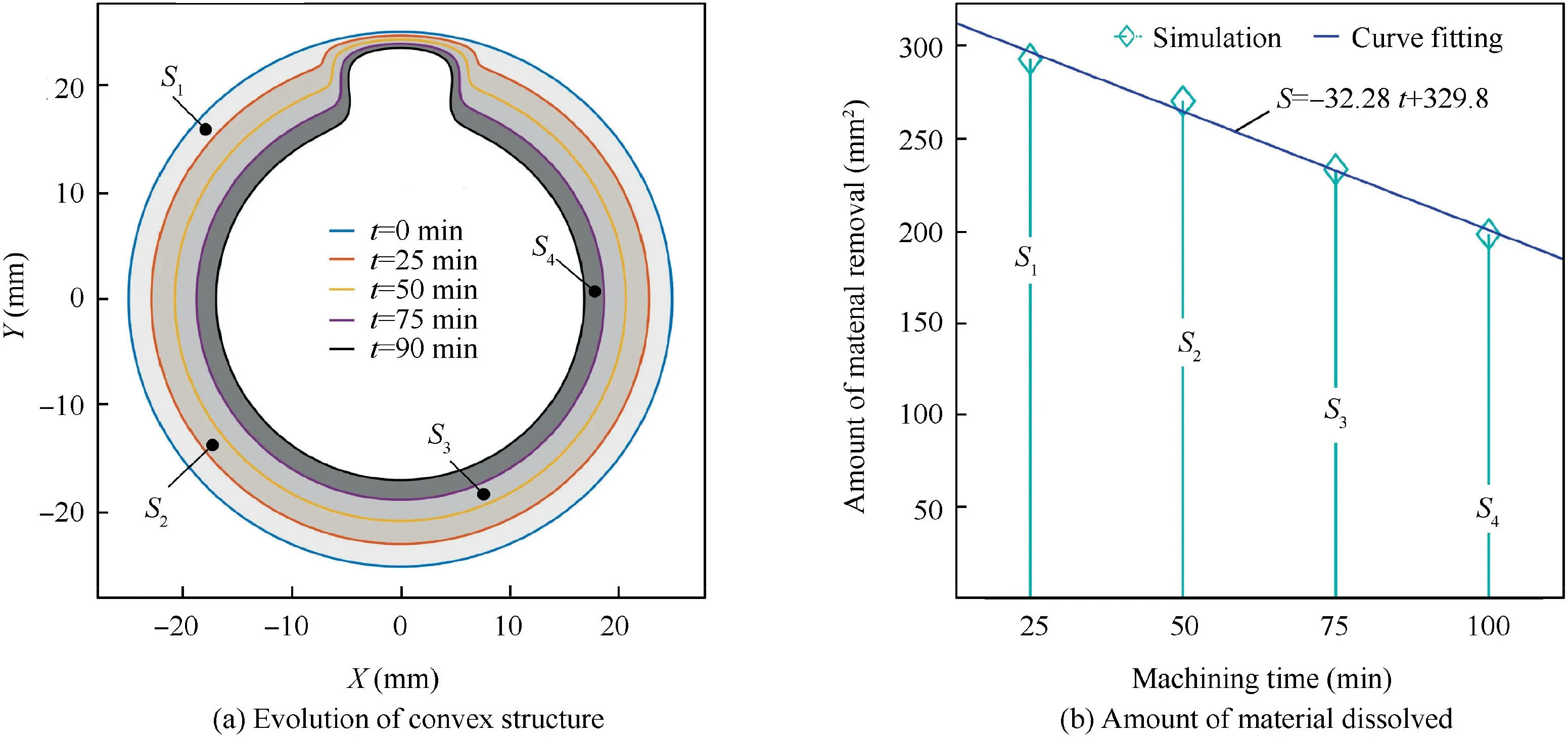
Fig. 5 Simulation results of convex structure.
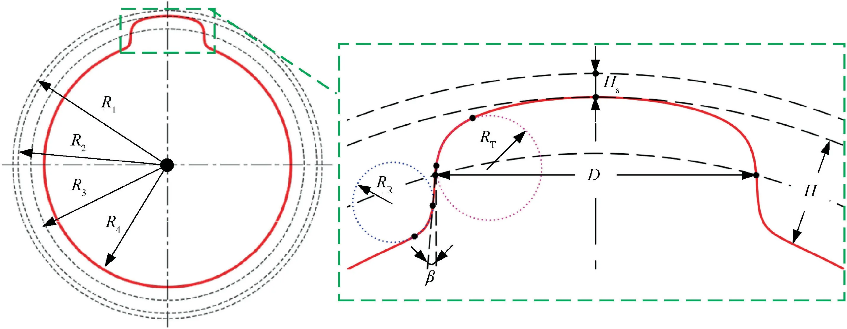
Fig. 6 Five quality indexes of convex.
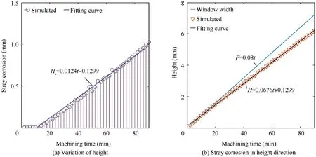
Fig. 7 Simulation results of height.
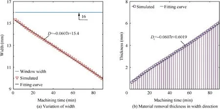
Fig. 8 Simulation results of width.
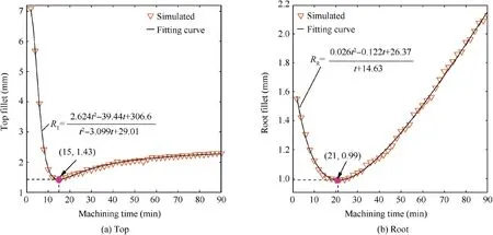
Fig. 9 Variation of fillet radius.
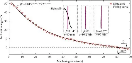
Fig. 10 Variation of inclination angle.
The height of the convex can be estimated as follow:

where R4is the radius of the finial workpiece.
The thickness (Hs) of stray corrosion can be calculated as:

where R1is the radius of the initial workpiece,R2is the radius at the top of the convex structure,F=vt,which is the cathode tool feed depth.
3.2.2. Width
According to Fig. 6, the width of the structure can be defined as the chord length of the circle,whose radius is R3,it is calculated as follows:

As the machining time increases, the width of the convex decreases linearly,which gradually moves away from the cathode window width in Fig. 8(a). This is because the material in the width direction is linearly removed, as shown in Fig. 8(b).
The width (D) of the convex can be estimates as follow:

The material removal thickness (Dt) in the width direction can be obtained:

3.2.3. Fillet radius at the top and root
In order to obtain the top and root fillet radius,the simulation data is fitted by using least squares, and the constraints to be met are as follows:
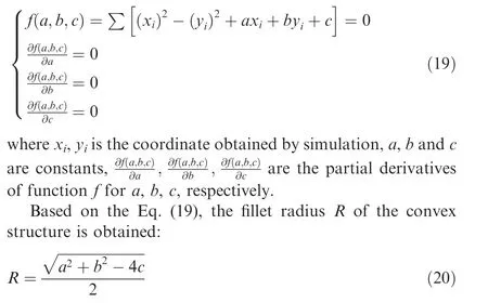
In Fig. 9, the top and root fillet radius show a trend of decreasing first and then increasing with time. The minimum top fillets radius is 1.43 mm at 15 min, and the minimum root fillets radius is 0.99 mm at 21 min.The top and root fillets radius can be expressed,and both of them fit the rational function:

3.2.4. Inclination angle
Based on the characteristics of the convex structure, it has an inclination angle β,which can be defined as the angle between the sidewall of the convex and the vertical direction, as shown in Fig. 6. According to the data fitting, the least squares method is used to solve the coefficients p, q of the regression line equation:
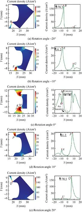
Fig. 11 Current density on surface of convex structure at different rotation angles.
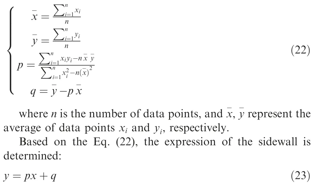
Fig. 10. shows the variation of the inclination angle. The results indicate that the inclination angle decreases with the increase of the machining time. When the machining time is 80.2 min, the inclination angle is zero. The closer the inclination angle is to zero degrees,the higher the machining accuracy of the convex is. When the machining time exceeds 80.2 minutes,the inclination angle is negative.In addition,the variation of the inclination angle satisfies the exponential function as follows:

3.3. Discussion
Based on the mathematical model for CRECM in Section 2,the variation of the current density on the anode surface at different rotation angles during the 30th rotation is investigated,as shown in Fig. 11. The different rotation angles can be divided into three parts. The first part is that the cathode window transfers into the processing area at rotation angles -20°and -10°, as shown in Fig. 11(a) and (b). The current density has inflection points (B, E) at the minimum gap, which decreases as the cathode window gradually transfers into the machining zone. This means that electrochemical dissolution is reduced in here. The high points (C, G) of stray current is on the convex top, which aggravates the stray corrosion in here.
The second part is that the cathode window faces the convex structure at rotation angle 0°, as shown in Fig. 11(c). Due to the current density on the convex surface is more than zero in Fig. 11, it can cause stray corrosion, and the thickness of stray corrosion increases with time in Fig. 6(b). The currents on the convex sidewall completes the material removal in the width direction, and the width of the structure decreases linearly with time in Fig.7(a).The current density on the sidewall region of the convex is steeply changed, this means that the position of the different height on the side wall causes uneven electrochemical dissolution, which produces an inclination angle β in Fig. 10. In addition, the current density between the sidewall and the top of the convex is arc transition, and the current density between the sidewall and the root of the convex holds three inflection points (I, K, M) on one side, in where the fillet corrosion occurs, and the variation of the fillet is shown in Fig. 9.
The third part is that the cathode window transfers out of the processing area at rotation angles 10° and 20°, as shown in Fig. 11(d) and (e). The stray current at the high points (N,U)is reduced,and the stray corrosion is weakened on the convex surface. The current density at the inflection points (P, Q)away from the convex surface becomes stronger,which means that the electrochemical dissolution increases in here.Based on the tool window continuously transferring into and out of the processing area, the convex structure is manufactured.
4. Experimental validation
4.1. Experimental procedure
Following the above simulations, a self-designed machining tool was used to study the evolution of the convex structureduring CRECM,as shown in Fig.12.The workpiece and tool rotated and fed linearly,which were controlled by shafts.10wt% NaCl was used as the electrolyte, which was cleaned through a filter. The electrical energy required during processing was provided by a DC power supply.In order to manufacture the convex structure on the workpiece surface, the tool surface was machined with a rectangular window, whose interior was insulated by ceramic. Experimental tests for different heights of the convex were conducted with different machining time:25,50,75 min and 90 min,and the machined surface profile was obtained by a coordinate measuring machine(CMM).The height H,the width D,the fillet RTat the top,the fillet RRat the root, and the inclination angles β of the convex were obtained by fitting the data points through Matrix Laboratory(MATLAB 2016a). Table 1 summarized the experimental parameters used for the CRECM.
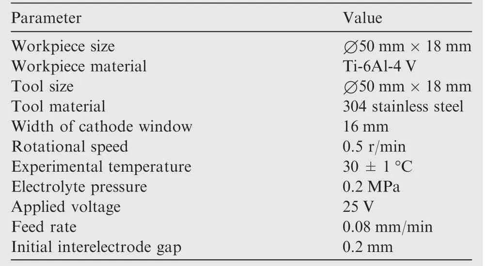
Table 1 Machining parameters for CRECM.
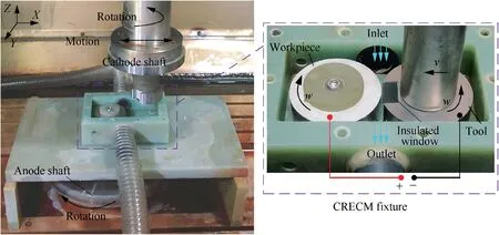
Fig. 12 Schematic of machining tool.

Fig. 13 Top-view of convex at different machining time.
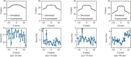
Fig. 14 Comparison of simulated and experimental results for convex profile at different machining time.
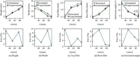
Fig. 15 Comparison of simulated and experimental quality indexes.
4.2. Experimental results
A series of machining tests are performed to validate the effectiveness of the proposed simulation model in CRECM at different machining time. Fig. 13 exhibits top-view profiles of the convex obtained at different machining time: 25, 50, 75,and 90 min. The results indicated that the cross-sectional profile of the convex is getting slimmer and higher with time, and the inclination angles of the sidewall gradually decrease. This fact is in good agreement with the simulated results, as shown in Fig. 14. As illustrated in Fig. 15, the five quality indexes were measured.With the increase of time,the height H,the fillet RTand RRshow an upward trend, the width D and the inclination angles β show a downward trend. The variations of these quality indexes are consistent with the Section 3.2.Based on consideration of the smaller inclination angle(-0.51°), the machining performance obtained at machining time of 90 min is found to be acceptable for the industrial applications.
5. Conclusions
(1) In this paper, the evolution of the convex structure is investigated based on kinematic modeling, which is verified by CRECM experiments.The main conclusions are as follows:
(2) The mathematical matrix equation for an equivalent kinematic model during CRECM is established, and the trajectory of the tool center satisfies the Archimedes spiral equation.
(3) The variations of the five quality indexes for the convex structure are obtained: as machining time increases, the height increases linearly, the width reduced linearly, the fillets at the top and root fit the rational function, and the inclination angle of the convex satisfies the exponential function.
(4) The simulation results indicate that stray current is the cause of stray corrosion on the top, and the inflection points and arc transition of the current density cause rounded corrosion at the root and top of the convex.The steep drop and uneven distribution of the current density on the sidewall of the convex produces an inclination angle,which can be obtained range from positive to negative.
(5) Experimental observations show a good correlation with the simulated values, and it can provide theoretical guidance to obtain desired convex structure during CRECM.
Declaration of Competing Interest
The authors declare that they have no known competing financial interests or personal relationships that could have appeared to influence the work reported in this paper.
Acknowledgements
The authors wish to acknowledge the financial support provided by National Natural Science Foundation of China(51805259), Natural Science Foundation of Jiangsu Province of China(No.BK20180431),Postdoctoral Science Foundation of China(No.2019M661833),Jiangsu Key Laboratory of Precision and Micro-Manufacturing Technology and Young Elite Scientists Sponsorship Program by CAST.
 CHINESE JOURNAL OF AERONAUTICS2021年3期
- CHINESE JOURNAL OF AERONAUTICS的其它文章
- Criteria for hypersonic airbreathing propulsion and its experimental verification
- Effect of scavenge port angles on flow distribution and performance of swirl-loop scavenging in 2-stroke aircraft diesel engine
- Ship detection and classification from optical remote sensing images: A survey
- Variational method based robust adaptive control for a guided spinning rocket
- Inertial parameter estimation and control of non-cooperative target with unilateral contact constraint
- Theoretical modeling of vectoring dual synthetic jet based on regression analysis
