Flow field generated by a dielectric barrier discharge plasma actuator in quiescent air at initiation stage
Xin ZHANG, Y.D. CUI, Chien Ming Jonathan TAY, B.C. KHOO
a State Key Laboratory of Aerodynamics, China Aerodynamics Research and Development Center, Mianyang 621000, China
b National University of Singapore, Singapore 119260, Singapore
KEYWORDS Dielectric barrier discharge;Particle image velocimetry;Plasma actuator;Schlieren technique;Wall jet
Abstract A single Dielectric Barrier Discharge(DBD)plasma actuator driven by Alternating Current (AC) power, capable of inducing a starting vortex and a wall jet in quiescent air, is suited for low-Reynolds-number flow control. However, the starting vortex and the wall jet are usually observed after the plasma actuator has been operated for dozens of and hundreds of cycles of the voltage, respectively. The detail of the induced flow field at the initiation stage of the plasma actuator has rarely been addressed. At the initiation stage, a thin jet that provides the impetus for the entrainment of the induced flow at the beginning of the plasma actuation is first observed by using a high-accuracy phase-lock Schlieren technique and a high-speed Particle Image Velocimetry (PIV) system. This is the initial form of the momentum transfer from the plasma to the fluid.Then,an arched type jet is created by the plasma actuator.In addition,the whole development process of the induced flow field from the starting point of the thin jet to the quasi-steady stage of wall jet is presented for providing a comprehensive understanding of the plasma actuator and proposing a relevant enhancement of the numerical simulation model.©2020 Chinese Society of Aeronautics and Astronautics.Production and hosting by Elsevier Ltd.This is an open access article under the CC BY-NC-ND license(http://creativecommons.org/licenses/by-nc-nd/4.0/).
1. Introduction
To promote the aerodynamic performance and flight safety of the aircraft, flow control using Dielectric Barrier Discharge(DBD) plasma actuators has been extensively studied, which includes anti-icing,1-7noise reduction,8-10assisted detonation initiation,11-13film cooling,14,15separation flow control,16-23boundary-layer control,24-28transition delay29-31and so on since the DBD plasma actuator has a few unique features,such as fast-acting,low power consumption and simple structure with no moving parts. The review on the research progress of the DBD plasma actuator can be found in recent literature.32-39
Classical DBD plasma actuator is generally made of two plate electrodes separated by an insulating film, with one electrode designated as the upper electrode,exposed to the air,and the other called the lower electrode, covered by the dielectric layer,as presented in Fig.1.When the two electrodes are connected to an Alternating Current (AC) high-voltage power supply,40-43microsecond-pulsed power supply,44-46Nanosecond-Pulsed (NS) power system47-54or pulsed-Direct-Current (DC) power supply,55the micro-discharge occurs and the air around the upper electrode is ionized. The plasma actuator under the different power supply can produce the different flow field in quiescent air. In the current investigation,only the flow field created by the Alternating Current Dielectric Barrier Discharge (AC-DBD) plasma actuator is discussed.
As an essential point for providing an insight into the controlling mechanism of the plasma actuator, the characterization of the flow field generated by an AC-DBD plasma actuator in quiescent air has been widely investigated. Despite different overall standpoints, the majority of the researches emphasize the starting vortex56and the wall jet which57dominate the initial period and the quasi-steady period of the flow field induced by the AC-DBD plasma actuator, respectively.However, the starting vortex and the wall jet are usually observed after the AC-DBD plasma actuator has been working for dozens of and hundreds of cycles of the voltage,respectively (shown in Fig. 2). For instance, in the study of Mishra and Panigrahi,58the actuation frequency of the high-voltage power,f,is 2 kHz(The cycle,T,is 0.5 ms).The starting vortex is observed at t=7.41 ms that is approximately equal to 14 cycles, while the wall jet is generated at t=90.80 ms that is equivalent to 181 cycles. For the whole evolution of the induced flow field,the flow structures which affect the development of the following flow field and play an important role in understanding the working principle of the plasma actuator in the first several cycles are a missing part and need to be further investigated.
More recently, Benard and Moreau performed Laser Doppler Velocimetry(LDV)measurements of the plasma jet with a high temporal resolution (20 μs) for fully understanding how the flow reacts to the momentum transfer created by the plasma when the plasma actuator is switched on.59The results suggested that the plasma jet is strongly non-stationary and the velocity of the plasma jet is different between the positivegoing cycle and the negative-going cycle. However, these results just gave the time evolution of the plasma jet at a local position and the whole induced flow field at the initiation stage was not clarified.
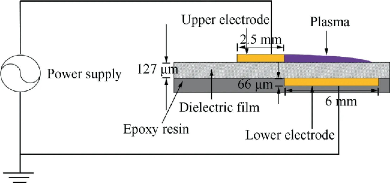
Fig.1 A side view schematic of a typical DBD plasma actuator.
To date, what happened on the flow field induced by the AC-DBD plasma actuator at the initiation stage is still not very clear.However,understanding the induced flow field during the first several cycles could provide comprehensive detail of the AC-DBD plasma actuator for proposing a relevant enhancement of the numerical simulation model and further exploring the controlling mechanism of the AC-DBD plasma actuator. Therefore, the induced flow field at the initiation stage needs to be studied deeply.
The present experimental investigation is stimulated by the requirement for a profound understanding of the flow field induced by an AC-DBD plasma actuator at the initiation stage of the plasma actuation. The purpose of this research is to investigate the evolution of the induced flow field using Particle Image Velocimetry (PIV) system and Schlieren visualization and provide a full picture of the induced flow characteristics from the starting point of the plasma actuation to the quasisteady states of wall jet.
2. Experimental setup
2.1. DBD plasma actuator
The geometry parameters of the asymmetrical DBD plasma actuator used in the present study are shown in Fig. 1. The plasma actuator consists of two electrodes which are arranged on each side of a dielectric film (127 μm thick KAPTON) and made of copper. The upper electrode (66 μm thick, 2.5 mm wide) is connected to a high-voltage power amplifier (Trek model 10/40A) and the lower one (66 μm thick, 6 mm wide)which is linked to the ground is wrapped by an epoxy resin.The length of the two electrodes is 100 mm. There is no gap or overlap between the two electrodes. The origin of the coordinate system employed here is located at the junction between the two electrodes. The x- and y-axis point to the tangential and normal directions, respectively. Here, the plasma is generated by applying sinusoidal AC waveforms with Eac=16 kVp-pat frequency f=1 kHz. The DBD plasma actuator is driven for duration t=2 s with a 100%duty cycle.
2.2. PIV experiments
The transient flow field generated by the DBD plasma actuator is studied quantitatively by using a planar, two-component LAVISION PIV system which includes a Phantom M320S high-speed camera (1920 pixels×1200 pixels resolution), a dual-cavity Nd:YLF laser(Litron LDY300),a high-speed controller and a system computer. The laser beam which emits from the laser head is generated by using cylindrical lens and spherical lenses and is adjusted by two knife edges. The laser sheet of the thickness of approximately 0.5 mm illuminates to the middle section plane of the plasma actuator. In order to obtain highly resolved images of the flow structures in the immediate vicinity above the plasma actuator,the image Field of View(FOV)which is aligned with the laser sheet is restricted to 6 mm×3 mm by using a Nikon Micro-Nikkor 200 mm macro lens, and image pairs are recorded at a frequency of 7000 Hz by sacrificing the resolution of camera, leading to a resolution of approximately 87 pixel/mm. The f-number of the lens is 50 (f-number=focal length/aperture). To prevent the environmental flow from affecting the induced flow field,the experimental platform including the DBD plasma actuator is placed in a 160 mm×160 mm Plexiglas chamber which is 740 mm in length. The dielectric oil-based particles (Ondina oil,mean diameter:0.8 μm)produced by an atomizer are seeding to the chamber. With a help of a NI card and a digital delay generator (Model DG645) with an accuracy of 5 ps,the operation of the DBD plasma actuator and the acquisition of the PIV system are synchronized. Davis 8.3 software from LAVISION is employed to process the original images with an interrogation window of 16 pixels×16 pixels and an overlap ratio of 50% to the inaccuracy of 3%-5% and spatial resolution of 0.09 mm∕vector.
2.3. Schlieren visualization
In addition,a Schlieren system(see Fig.3),which is made of a Nanonolite flash lamp (25 mJ∕pulse) for providing illumination, a camera (PCO 1600: 1600 pixels×1200 pixels) with an AF-S Nikon lens of 28-300 mm, and two chromatic lenses(1.9 m focal length), and where knife-edge filter is mounted on a self-balancing optical table,is used for recording the flow field created by the DBD plasma actuator at the initiation stage. A light beam radiated from the Nanonolite flash lamp operates with an exposure time of 23 ns which determines the shooting time.The knife-edge filter is adopted for adjusting the amount of light passing through. Meanwhile, the trigger signals which are generated by a digital delay generator(Model DG645)with an accuracy of 5 ps are used for precisely synchronizing the Nanonolite flash lamp, the high-voltage power supply and the PCO camera,and achieving a high accuracy phase-lock image freezing Schlieren technique.The size of the FOV is 120 mm×90 mm, resulting in a resolution of approximately 13.3 pixels/mm.
3. Results and discussion
3.1. Electrical characteristics of plasma actuator
The plasma discharge captured by a PCO camera (1600 pixels×1200 pixels) with a exposure time of 1 s is presented in Fig. 4(a) for understanding the electrical characteristics of the plasma actuator and providing the validation of results.The plasma discharge seems to have a quasi-uniform glow and is consistent with the previous study.60Actually, this discharge consists of two typical types of micro-discharges,namely the streamer discharge occurring in the positivegoing cycle and the glow-like discharge developing during the negative-going cycle,which can be captured by an Intensified Charge Coupled Device (ICCD) camera.60,61However,because of the limited sensitivity of the PCO camera, these micro-discharges cannot be recorded by the PCO camera with the short exposure time of several microseconds in the present investigation. More detailed information on both types of discharges can be found in recent study.60,61

Fig. 3 Sketch map of experimental set-up for Schlieren system.
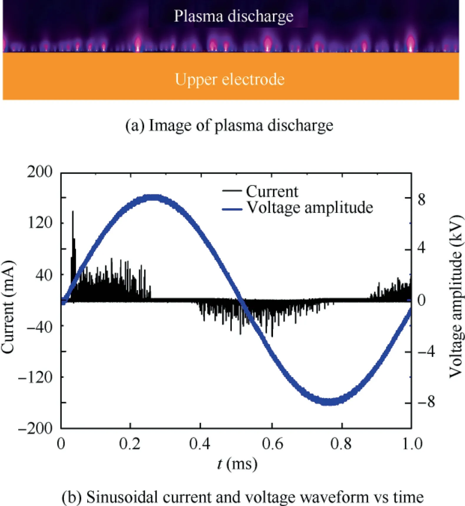
Fig. 4 Image of plasma discharge and Sinusoidal current and voltage waveform vs time.
With a help of a high-voltage probe(Tektronix P6015A),a shunt of 70 Ω and an oscilloscope (Yokogawa DLM-2054)with a bandwidth of 500 MHz, the characterizations of the high-voltage waveform and the current over time are shown in Fig. 4(b). The shunt is placed in series between the lower electrode and the ground, and the oscilloscope is used for digitalizing the signal.60,61It can be found that the discharge current is made of two evident parts by both positive- and negative-going cycle, which is related to the two types of micro-discharges. Some high current spikes in the positivegoing cycle exist and the maximum value of the current is approximately 140 mA. This can be associated with the streamer discharge which is filamentary and is capable of releasing energy for a short time, while the glow-like discharge which is developing in the negative-going cycle causes several current pulses of reduced amplitude.The present study is in agreement with the previous investigations.60,61
3.2. Time-averaged and quasi-steady flow field
The time-averaged velocity field induced by the plasma actuator and measured by the PIV system is shown in Fig. 5(a).Here, Upand Vpare the velocity components in the x- and y-direction, respectively. Initially, the pattern of the flow field is similar to the classical laminar wall jet. However, there is no mass added to the flow.62The DBD plasma actuator draws the ambient air towards the wall due to the pressure difference between the vicinity of the surface and the outside area.62Then a tangential flow is ejected from the upper electrode to the downstream due to the body force created by the plasma actuator. The maximum velocity of the wall jet is measured at approximately 0.5 mm above the upper electrode,which agrees well with the previous study.61The quasi-steady wall jet recorded by the Schlieren system (see Fig. 5(b)) is approximately identical to the feature of the time-averaged flow field.
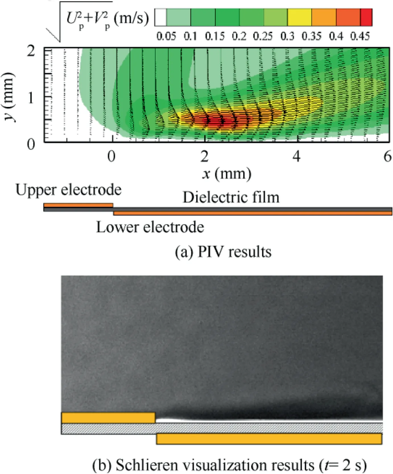
Fig. 5 Time-averaged flow field and quasi-steady flow field induced by asymmetrical plasma actuator.
Although the time-averaged flow field provides the validation of the results by comparing with Ref. 61, this flow field cannot reveal the formation mechanism of the pressure difference between the near-wall area and the outside region, which is the original impetus for drawing the outside flow towards the wall and will be discussed in the next section.
3.3. Time resolved flow field in the first cycle
In this section,the induced flow field which is used for figuring out the original flow field and uncovering the impetus of drawing the air above the upper electrode in the first cycle on the initiation of the AC-DBD plasma actuator is presented in Fig. 6. The time of onset of the plasma actuator is stated as t=0 s and the continuous working time of the plasma actuator is 2 s.
Based on the previous discussion in Section 3.1, the results can be divided into two parts by the two prominent half-cycles,namely the positive-going cycle and the negative-going cycle since the micro-discharge of the DBD plasma actuator has two distinct different discharge regimes which can affect the induced flow field in the two half-cycles during one AC sinusoidal period.60
A thin jet as an evident flow structure can be observed in the positive-going cycle of the first period (see Fig. 6(a)-Fig.6(c)).As the AC-DBD plasma actuator reaches the breakdown voltage amplitude,the charged particles are formed and move under the influence of the electric field,imparting a body force on the surrounding air and leading to a thin jet at t=0.143 ms (see Fig. 6(a)). This finding in the present study agrees with the previous investigation by Whalley and Choi who reported that plasma ions transferred momentum to the air in the horizontal direction along the wall at the initiation stage and created the entrainment effect.62However, their studies did not show this thin jet.62The thin jet is the initial form in which the momentum generated by the plasma is transferred to the still flow field.The induced thin jet is different from the quasi-steady wall jet created by the DBD plasma actuator which has been working for hundreds of cycles of the voltage (see Fig.5). Initially, the covered length of the thin jet is approximately 2 mm,while the coverage region of the quasisteady wall jet can reach more than a dozen millimetre.60Meanwhile, the thickness of the thin jet is much smaller than the quasi-steady wall jet (this will be analyzed further in the next section).53With time, the velocity of the thin jet is increased (see Fig. 6(b) and Fig. 6(c)). This thin jet results in the pressure gradient in the vertical direction59and is the initial engine for drawing the ambient air towards the wall at the beginning.To our knowledge,it is the first time that the investigation provides a detailed description of the induced flow field at the initiation stage of the plasma actuation.
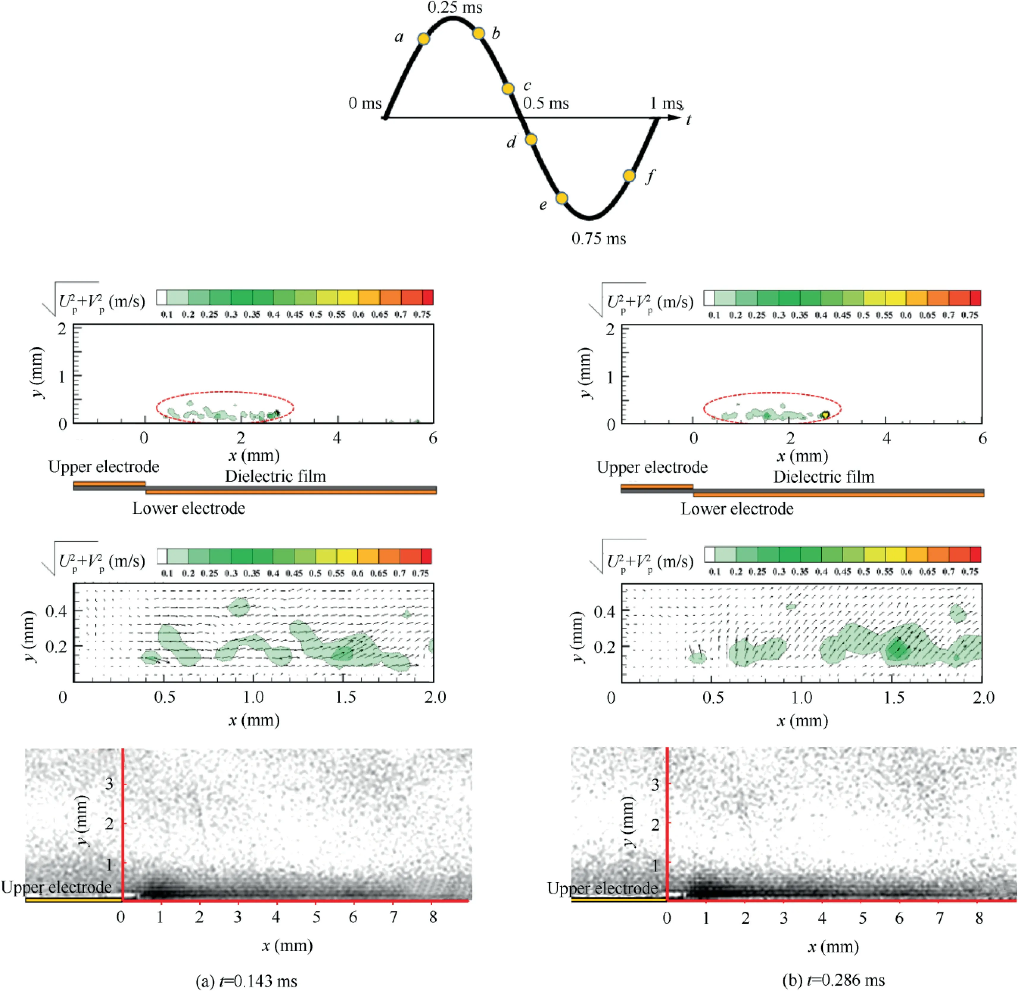
Fig. 6 Instantaneous flow field induced by plasma actuator in the first cycle.
In the negative half cycle,the entrainment occurs above the upper electrode because of replenishing the thin jet that has been ejected by the body force in the horizontal direction during the positive-going cycle. However, this entrainment does not generate the starting vortex immediately and induces an arched jet which detaches from the surface, as presented in Fig. 6(d). This arched jet which is similar to the flow field induced by a sliding discharge plasma actuator limits losses at the dielectric surface and promotes a flow detachment from the wall, which may be helpful to decrease the skin friction of the surface.60,63Although the velocity of the arched jet is very low,the arched jet has potential benefits for flow control owing to its ability to create the perturbations in the vicinity of the dielectric surface and promote the mixing between the main flow and the low-speed flow close to the wall.Based on the previous literature,64the AC-DBD plasma actuator which is similar to a point source can produce a series of pressure waves during the positive-going cycle. The pressure value of these pressure waves is inversely proportional to distance between the plasma actuator and the pressure sensor, which suggested that these induced pressure in the vicinity of the wall could be thousands of Pascal and are capable of lifting the air near the wall. Combining the pressure waves and the entrainment which occurs for replenishing the air that has been ejected by the thin jet, the arched jet could be created in the negativegoing cycle. As time goes on, the starting point of the arched jet is moving to the downstream of the plasma actuator, as depicted in Fig. 6(e) and Fig. 6(f).
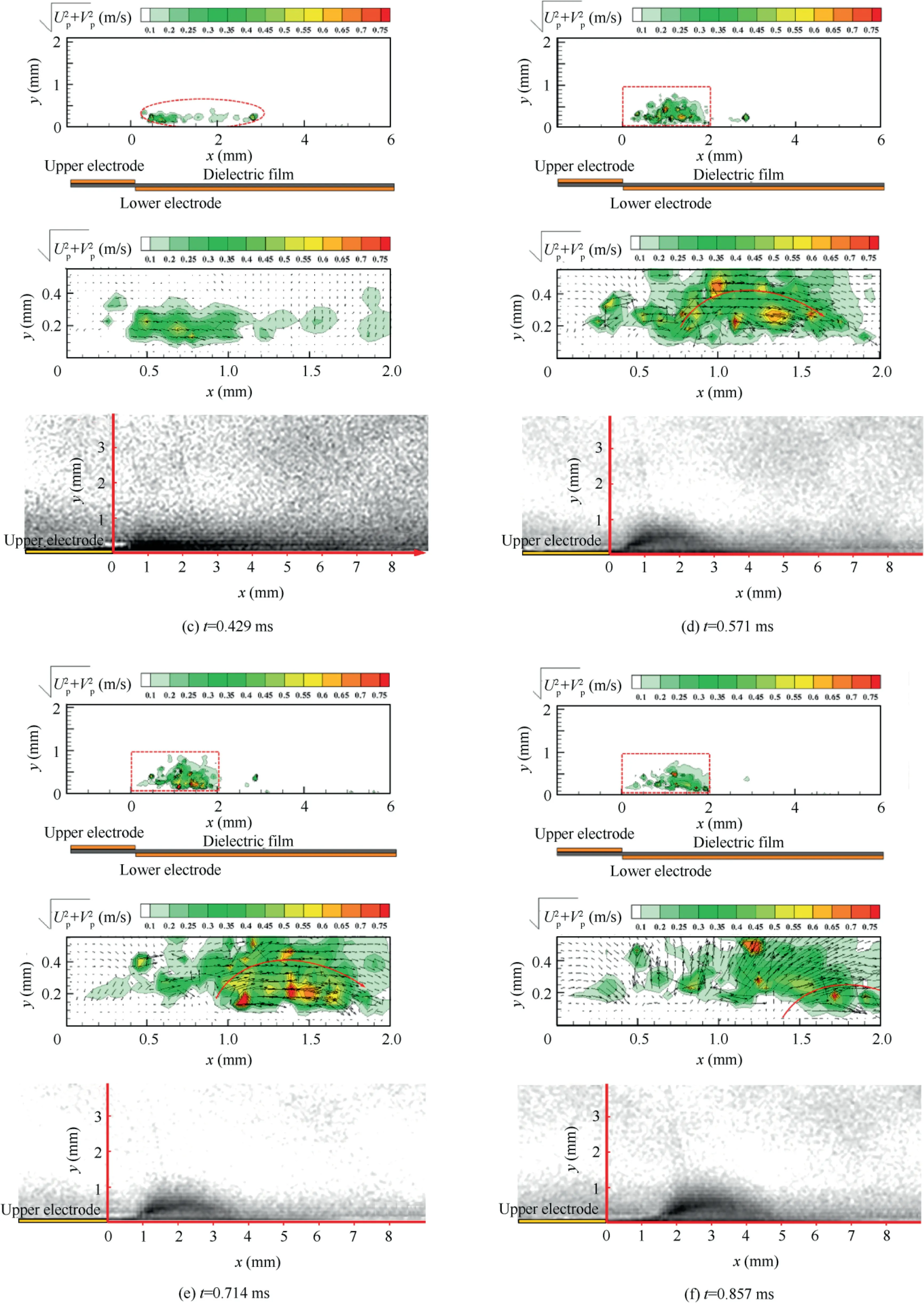
Fig. 6 (continued)
As mentioned previously, the DBD plasma actuator can produce a thin jet and an arched jet in the positive-going cycle and the negative-going cycle, respectively, at the initiation stage of the plasma actuation.In this part,a further discussion of the two flow structures is presented. Fig. 7(a) presents the non-dimensional horizontal velocity profile of the thin jet for several x locations at t=0.143 ms. Here, Upis the velocity induced by the plasma actuator in the x-direction and Upmaxis the maximum induced velocity in the x-direction. The maximum horizontal velocity is obtained about 0.14 mm above the surface of the dielectric film.This position where the maximum horizontal velocity is located is lower than the position of the maximum horizontal velocity of the quasi-steady wall jet,suggesting that the thickness of the thin jet is smaller than the thickness of the quasi-steady wall jet.In addition,the thickness of the thin jet is approximately invariant with increasing x values.Fig.7(b)presents the non-dimensional horizontal velocity profile of the thin jet versus time. The maximum horizontal velocity increases with time.
On the other hand, the arched jet can be observed in the negative-going cycle of the first cycle. To profoundly describe this new type jet, some parameters which are shown in Fig. 8 are defined.The parameters α1and α2represent the rising angle and the falling angle of the arched jet, respectively. These two deflection angles, α1and α2are formed between the median of the thin jet and the positive and negative directions of the x axis,respectively(see Fig.8).43The parameter d is the distance between the starting point and the end location of the arched jet,which represents the span of the arched jet.The maximum uncertainties of these parameters are approximately 10%by 10 repeat measurements of a single set of data since the microdischarge is stochastic. However, this is a preliminary study and an on-going topic that needs further investigation for establishing the mathematic model.
Fig.9(a)presents the two deflection angles,α1and α2versus time.The rising angle,α1,is approximately constant with time and the falling angle, α2, decreases with time. The span of the arched jet (see Fig. 9(b)) increases with time, indicating that the influence scope of the arched jet is expanding with time.
3.4. Time resolved flow field in the second cycle
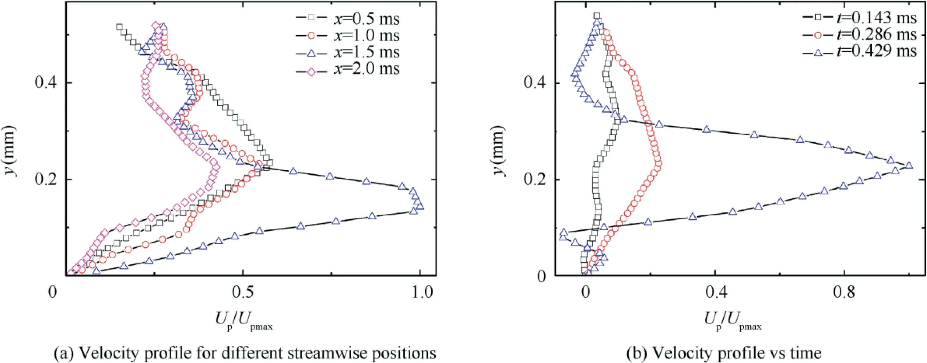
Fig. 7 Non-dimensional velocity profile for different streamwise positions (t=0.143 ms) and vs time.

Fig. 8 Nomenclature of the parameters of arched jet.
The flow field induced by the plasma actuator in the second cycle is shown in Fig. 10. In the first cycle, the thin jet and the arched jet have been ejected and the pressure gradient between the region close to the wall and the outside area is formed. As time goes, the starting vortex occurs due to the enhancement of the entrainment which is caused by the pressure gradient, as shown in Fig. 10(a). Then, the size of the starting vortex increases with time, which agrees with the previous investigation,56,62as presented in Fig. 10(b)-Fig. 10(d).Meanwhile,the thickness of the induced jet increases with time because of the cumulative effect reported by Benard and Moreau,60as shown in Fig. 10(e)-Fig. 10(f).
If the stage in which the thin jet occurs is defined as the first stage, the stage of the arched jet is the second stage and the start vortex stage is the third stage. In the first stage, the thin jet provides the impetus for the entrainment at the beginning.In the second stage, the arched jet can extend the influence region of the jet and create small perturbation. During the third stage of the starting vortex,the starting vortex dominates the induced flow field and becomes the main engine for the development of the jet by moving away from the surface of the dielectric film, promoting the mixing between the outside flow and the flow near the wall and increasing the thickness of the wall jet.
3.5. Instantaneous induced flow field in other cycles
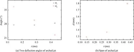
Fig. 9 Two deflection angles of arched jet and span of arched jet vs time.
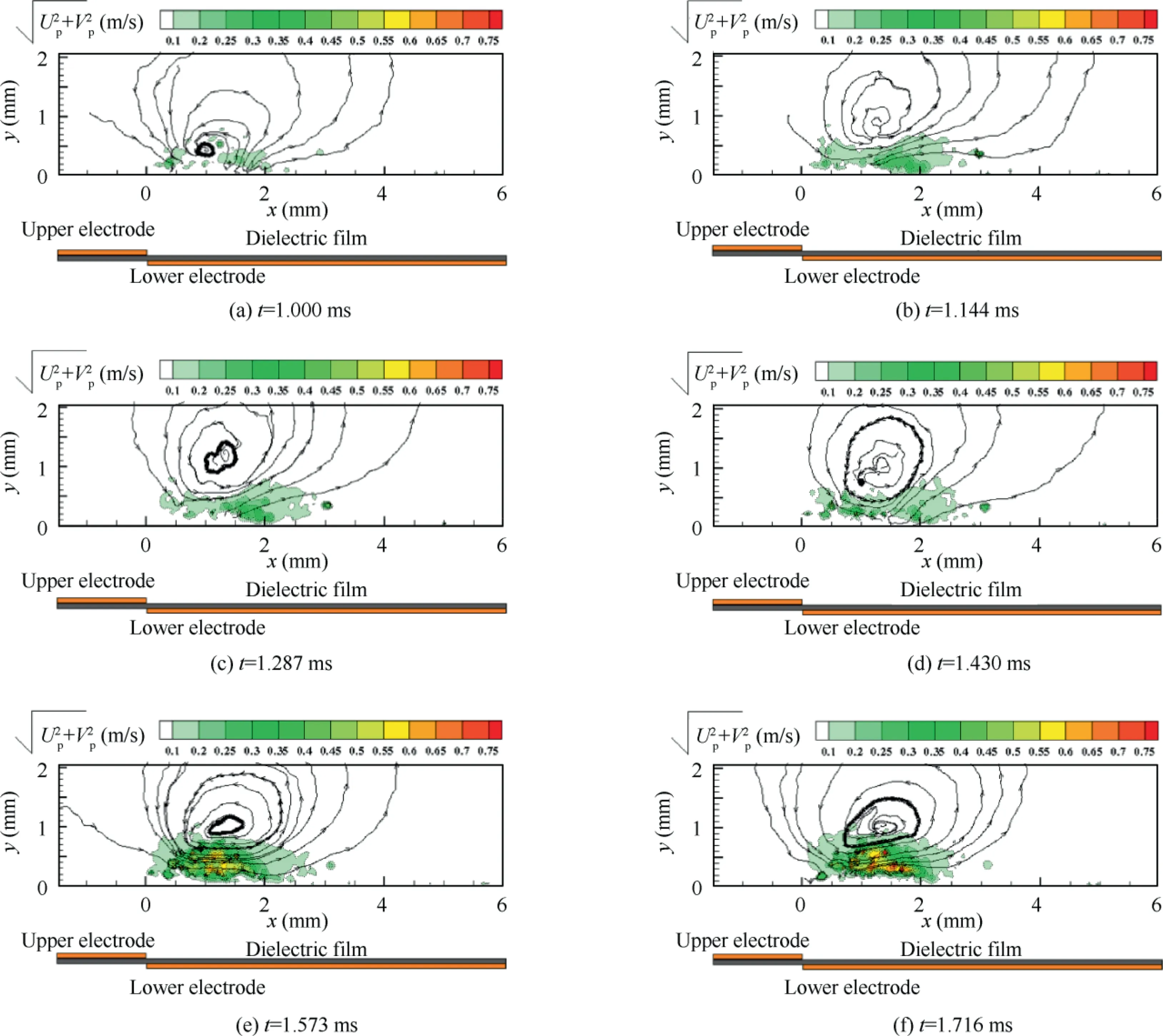
Fig. 10 Instantaneous flow field induced by plasma actuator in the second cycle.
Fig. 11 presents the instantaneous induced flow field in other cycles.From the 4th cycle to the 20th cycle,the starting vortex still plays an important role in development of the jet, as shown in Fig. 11(a)-Fig. 11(c). As time goes, the starting vortex moves out of the observation window, and a deflection angle, α, which is defined between the median of the induced jet and the positive direction of the x-axis,43decreases with time since the influence of the starting vortex is reduced (see Fig.11(d)).When the deflection angle,α,is approximately constant, the flow field reaches a quasi-steady status, as shown in Fig. 11(e)-Fig. 11(f), which suggests that the flow field enters the fourth stage. Interestingly, the deflection angle, α, can be considered the mirror of the status of the induced flow field.In the fourth stage,the effect of the starting vortex is gradually reduced and the wall jet dominates the induced flow field.
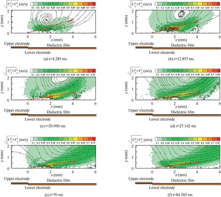
Fig. 11 Instantaneous flow field induced by plasma actuator in other cycles.
3.6. Discussion on whole development process of induced flow field
From the results shown in the previous sections, the whole development process of the induced flow field from the starting point of the thin jet to the quasi-steady stage of wall jet can be presented schematically in Fig. 12.
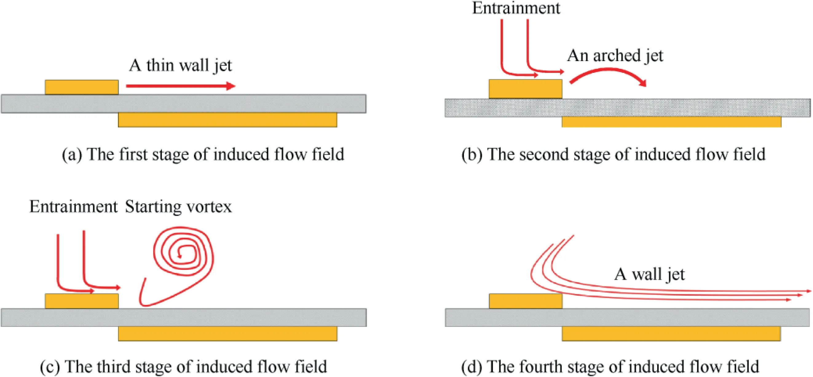
Fig. 12 Instantaneous flow field induced by plasma actuator at different stages.
Initially, the horizontal thin jet is first observed in the positive-going cycle of the first period and can be defined as the first stage (see Fig. 12(a)), which provides the original impetus for the entrainment. Then an arched jet (see Fig. 12(b)) which occurs in the negative-going cycle and extends the influence region of the jet can be called the second stage.Based on Ref. 64, it is suspected that the combined effect between a series of pressure waves created by the plasma actuator which has the ability to lift the air and the entrainment which acts for replenishing the air that has been ejected by the thin jet might be the formation mechanism of the arched jet. As time goes,the starting vortex gradually governs the flow field and promotes the mixing between the outside flow and the flow in the vicinity of the wall in the third stage,62as depicted in Fig. 12(c). As the starting vortex gradually moves away from the wall, the wall jet dominates the induced flow field in the fourth stage and the deflection angle of the wall jet is approximately constant, as shown in Fig. 12(d). This discussion on the full picture of the induced flow field can provide a comprehensive understanding of the AC-DBD plasma actuator and lay the foundation for proposing a relevant enhancement of the numerical simulation model.
The present investigation may open further discussion on the flow field induced by the AC-DBD plasma actuator.How to use these flow structures generated by the AC-DBD plasma actuator at the initiation stage, such as the thin jet,the arched jet which can create some perturbations near the wall and be helpful for boundary layer flow control,is required to further study.
4. Conclusions
The flow field generated by a single AC-DBD plasma actuator at the initiation stage has been investigated using a high-speed PIV system and Schlieren visualization in quiescent air. Based on the characteristics of the induced flow field, the induced flow field can be divided into four stages.
Initially,the thin jet is first observed in the first stage,which leads to a pressure gradient in the vertical direction and provides the initial impetus for pulling the ambient air towards the wall. This thin jet is the initial form in which the momentum generated by the plasma is transferred to the still flow field. Compared to the quasi-steady wall jet created by the plasma actuator which has been working for dozens of or hundreds of cycles of the voltage, the thickness and the covered region of the thin jet are much smaller. Then, an arched jet which detaches from the surface is created by the plasma actuator in the second stage. Although the velocity of the arched jet is very low, the arched jet has potential benefits for flow control due to its ability to create the perturbations in the flow. In the third stage, the starting vortex gradually governs the induced flow field and the arched jet seems to disappear.The starting vortex is moving away from the wall surface and promoting the mixing between the outside flow and the flow near the wall. As the starting vortex gradually moves away from the wall, the wall jet dominates the induced flow field in the fourth stage and the deflection angle of the wall jet is approximately constant, which agrees with the previous investigations.56
The present investigation provides the whole development process of the induced flow field by a single AC-DBD plasma actuator and lays a foundation for proposing a relevant enhancement of the numerical simulation model. However, it is just the start and further studies are still needed to carry out some investigations simultaneously, such as the induced flow field, fast imaging of plasma discharge and temperature measurement,for providing a better understanding of the relationship between the discharge regime and the induced flow field generated by the DBD plasma actuator at the initiation stage. This is of significance in the engineering applications of the DBD plasma actuator.
Declaration of Competing Interest
The authors declare that they have no known competing financial interests or personal relationships that could have appeared to influence the work reported in this paper.
Acknowledgements
The authors gratefully acknowledge the financial support of the research project by the National University of Singapore,and Dr.Zhang Xin acknowledges the support by the National Natural Science Foundation of China (No. 11902336), State Key Laboratory of Aerodynamics Foundation of China(Nos. SKLA2019020201 and JBKYC190103), CARDC Fundamental and Frontier Technology Research Fund (No.PJD20180144) and China Scholarship Council.
 CHINESE JOURNAL OF AERONAUTICS2021年3期
- CHINESE JOURNAL OF AERONAUTICS的其它文章
- Criteria for hypersonic airbreathing propulsion and its experimental verification
- Effect of scavenge port angles on flow distribution and performance of swirl-loop scavenging in 2-stroke aircraft diesel engine
- Ship detection and classification from optical remote sensing images: A survey
- Variational method based robust adaptive control for a guided spinning rocket
- Inertial parameter estimation and control of non-cooperative target with unilateral contact constraint
- Theoretical modeling of vectoring dual synthetic jet based on regression analysis
