Three-Dimensional Trajectory Optimization for Secure UAV-Enabled Cognitive Communications
Yuhan Jiang,Jia Zhu
School of Telecommunications and Information Engineering,Nanjing University of Posts and Telecommunications,Nanjing 210003,China
Abstract: Unmanned aerial vehicles(UAVs)are envisioned as a promising means of providing wireless services for various complex terrains and emergency situations.In this paper,we consider a wireless UAVenabled cognitive communication network, where a rotary-wing UAV transmits confidential information to a ground cognitive user over the spectrum assigned to primary users (PUs), while eavesdroppers attempt to wiretap the legitimate transmission.In order to enhance the secrecy performance of wireless communications,the secrecy rate(SR)of the UAV-enabled cognitive communication system is maximized through optimizing UAV three-dimensional(3D)flying trajectory while satisfying the requirements of UAV’s initial and final locations and guaranteeing the constraint of maximum speed of UAV and the interference threshold of each PU.However, the formulated SR maximization(SRM)problem is non-convex.For the purpose of dealing with this intractable problem,we employ the difference of two-convex functions approximation approach to convert the non-convex optimization problem into a convex one, which is then solved through applying standard convex optimization techniques.Moreover, an iterative 3D trajectory optimization algorithm for SRM scheme is proposed to achieve the near-optimal 3D trajectory.Simulation results show that our proposed 3D trajectory optimization based SRM algorithm has good convergence,and the proposed SRM scheme outperforms the benchmark approach in terms of the SR performance.
Keywords: UAV-enabled cognitive communications;physical-layer security;trajectory optimization
I.INTRODUCTION
Recently, with the vigorous development of the mobile Internet and the rapid popularization of smart terminals, the requirements for seamless networks coverage and high-speed data transmission have become increasingly stronger [1–3].Different from the fixed infrastructures, unmanned aerial vehicles(UAVs) have the advantages of sufficient flexible deployment, high maneuverability, low operating and maintenance costs, as well as additional design degrees of freedom[4–7].Thus,UAVs play an irreplaceable role in the future communication networks[8,9].In particular,UAVs are widely used in public and civil applications [10–13].However, due to the heterogeneous coexistence of different wireless networks in the UAV communication network,it is difficult to supervise endless malicious UAV incidents,resulting in various communication security attacks such as interference and eavesdropping [14, 15].Therefore, it is important and urgent to investigate the methods to enhance the physical-layer security(PLS)[16]for UAV communication networks.
Due to the broadcast characteristics of wireless propagation channels, eavesdropping events are unavoidable.Coupled with the fact that the communication between ground users and UAVs are readily overheard by eavesdroppers,the information transmission of legitimate users is vulnerable to hybrid attacks by various eavesdroppers [17, 18].Thus, extensive research work is devoted to exploring methods to combat eavesdropping [19–22].Specifically, the authors of[19]and[20]employed a UAV-based air-to-ground friendly jammer to emit jamming signals to defend against eavesdropper, which effectively improves the security performance of legitimate transmission between transmitter and receiver.For multiple UAVs scenario,the average secrecy rate(SR)from the UAV sender to the terrestrial receiver was maximized by designing flying path and allocating transmit power in a two-UAV wireless communication network, where one UAV transmitted confidential signals to the destination,while another UAV sent the jamming signals to confuse the illegitimate users[21].Moreover,in[22],the authors employed multiple UAVs to send jamming signals to degrade the eavesdropper’s quality-ofservice in industrial Internet of Things, which shows that the proposed scheme could significantly degrade the quality of eavesdropping links while having nearly no influence on the legitimate signals transmission.
Meanwhile,for the purpose of improving the PLS of the UAV wireless system,considerable attentions have been paid to the UAV PLS enhancement methods,including trajectory design [23, 24], resource management[25,26]and so on.To be specific,the authors of[23] maximized the SR of a dual-UAV-enabled wireless network via jointly designing UAV trajectory and user scheduling under the constraints of the maximum UAV velocity,the UAV return,and the UAV collision.In [24] and [25], a joint UAV flight trajectory, transmission power,and ground terminals association optimization problem was investigated to improve the SR of terrestrial users in a downlink UAV-enabled wireless network, which effectively enhances the PLS of UAV communications and ensures the fairness among ground terminals.Furthermore, the authors in [26]studied a joint transmit power and flying route optimization framework to improve the PLS of the UAV wireless communication network.
Most existing work is devoted to designing the UAV trajectory with a constant flight altitude.However,the flight altitude has a great impact on the SR performance of the UAV communication network.Motivated by this,we optimize the UAV’s 3D flying route to maximize the SR of the UAV-enabled cognitive communication,where a UAV is employed to transmit confidential signals to terrestrial cognitive user (CU)over the spectrum allocated to primary users (PUs),while eavesdroppers attempt to wiretap the legitimate transmission.We summarize the major contributions of this paper as follows.
• We investigate the problem of 3D flying trajectory optimization to maximize the SR of a wireless communication network comprising of a rotarywing UAV,a CU,multiple PUs and eavesdroppers(Es).In this context, we formulate a 3D trajectory optimization based SRM problem under the constraints of the predefined UAV’s locations and velocity,the maximum speed of the UAV as well as the interference threshold of each PU.
• The proposed 3D trajectory optimization based SRM scheme is a non-convex optimization problem.For the purpose of handling with this intractable optimization problem,we apply the difference of the two-convex functions (D.C.) approximation approach to convert the non-convex optimization problem into a convex one,which is then solved by CVX.Finally,an iterative 3D trajectory optimization algorithm based SRM problem is presented to obtain the near-optimal UAV trajectory.
• Simulation results are given to demonstrate the effectiveness of convergence performance for the proposed 3D trajectory optimization based SRM algorithm.Moreover, they also present that the SRM method obtains a better secrecy performance than the benchmark method.
We organize the remainder of this paper as follows.Firstly, the system model of a UAV-enabled cognitive wireless communication system and the corresponding 3D trajectory optimization based SRM problem are given in Section II.Section III describes the method to solve the proposed SRM problem as well as presents an iterative 3D trajectory optimization algorithm based SRM problem with the aid of the D.C.programming approach.In Section IV, simulations are carried out to show the superiority of the proposed 3D trajectory optimization based SRM scheme.Finally, some remarks are concluded in Section V.We put proof in the Appendix to make the main text readable.
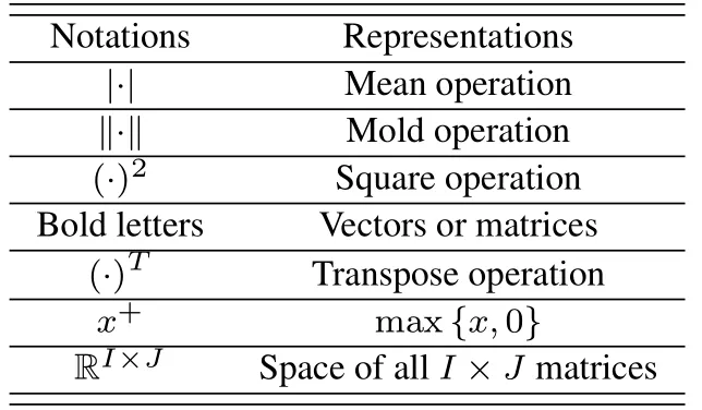
Table 1. Notations and representations.
II.SYSTEM MODEL AND PROBLEM FORMULATION
In this section,we introduce the system model used in this paper, and then formulate the 3D trajectory optimization based SRM problem.For the reason that the proposed optimization problem has an infinite number of variables over time, we employ the discrete linear state-space approximation method to handle with the proposed original continuous SRM problem.
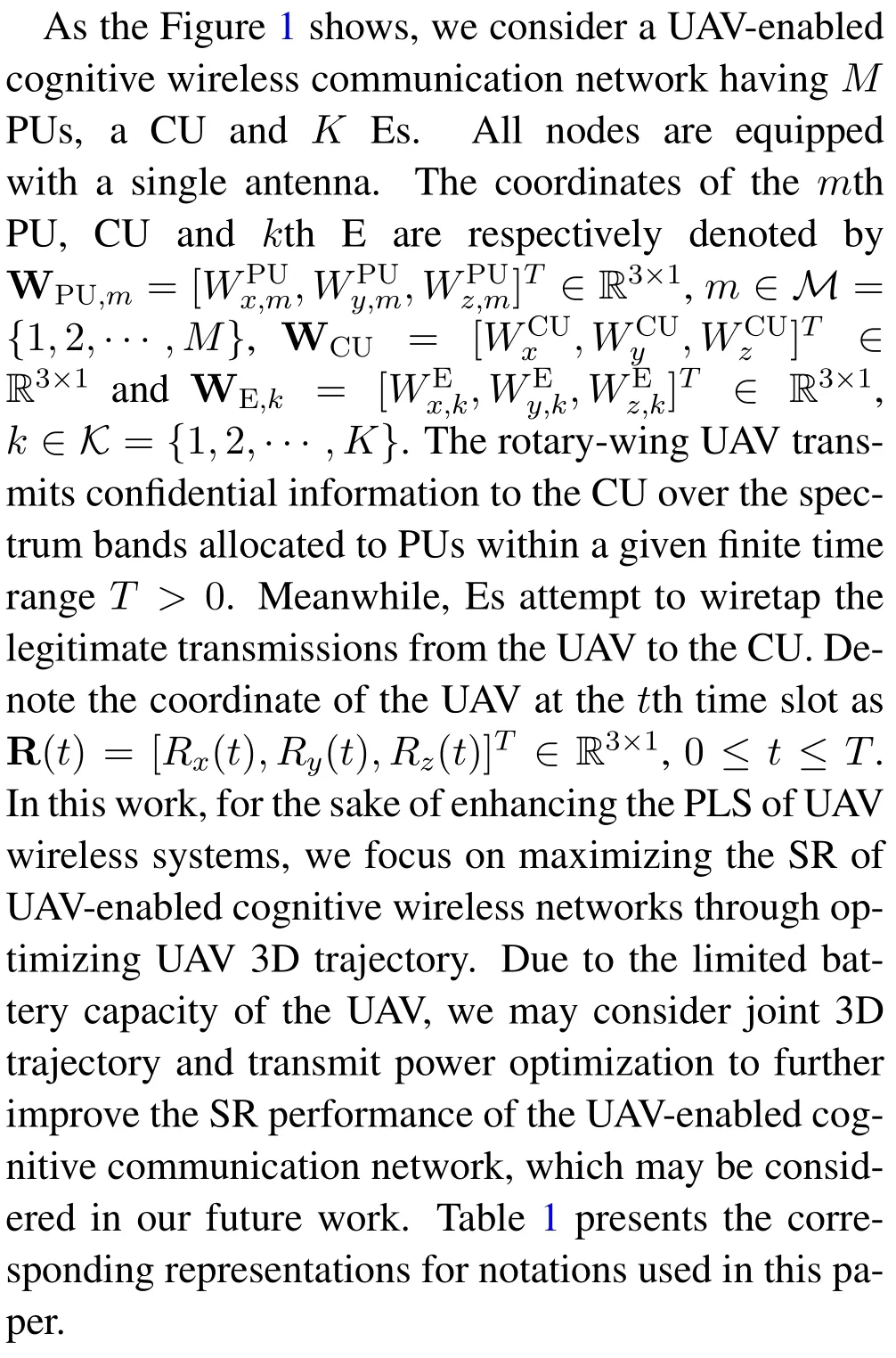
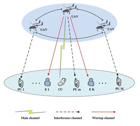
Figure 1. System model for secure communication in a UAV-enabled cognitive communication network.
The time-varying channel fading from the UAV to the CU andkth E can be respectively expressed by

and

whereβCU(t)andβE,k(t)are respectively large-scale fading effects from the UAV to the CU andkth E,and the complex-valued random variables(t)and(t)respectively denote the small-scale fading coefficients from the UAV to the CU andkth E with E= 1 and E= 1.Moreover, the large-scale fadingβCU(t) is usually dependent on the probabilities of occurrence of line-of-sight(LoS) and non-line-of-sight (NLoS) links, which can be written as

whereβ0is the path loss at the reference distance,dCU(t)is time-varying distance between the UAV and the CU,αis the path loss exponent,andκ <1 is the additional attenuation factor due to the NLoS condition.According to[7]and[27],the probability of LoS connection between the UAV and CU is given by

whereAandBare constants depending on the environment, and the elevation angle in degreeθCU(t) is expressed by

Thus, the large-scale fading coefficient between the UAV and the CU can be written as

Then, the signal-to-interference-plus-noise ratio at the CU can be obtained as

wherePUdenotes the sending power of UAV,NCU+ICU,NCUandICUare respectively the additive white Gaussian noise(AWGN)power and the interference power encounters at the CU.The achievable rate between the UAV and CU is expressed as

Since it is hard to obtain the probability distribution ofRCU, we are going to focus on analyzing the average communication throughput,which is defined asand we have
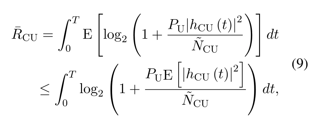
As observed from (8), the UAV flight trajectory not only affects the distance between the UAV and CUdCU(t), but also has an impact on the value of the probability of LoS linkPCU,LoS(t), which increases the difficulty of 3D trajectory optimization.According to [28], one effective method is to approximate the LoS probability homogeneously,that isThus, the average communication throughput between the UAV and CU can be rewritten as

Similarly, the achievable rate from the UAV tokth E is

Therefore,the aggregated SR of the UAV-enabled cognitive communication network is expressed by
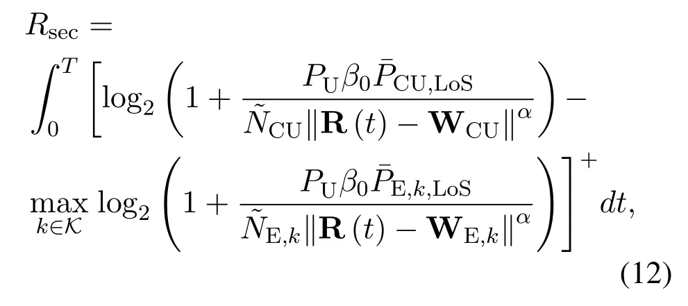

The aim of this paper is to maximize the SR of UAVenabled cognitive communication networks through jointly designing UAV path, velocity and acceleration.We consider the SR maximization(SRM)problem based on the following constraints:
1.The initial and final location constraints of the UAV are respectively given by

where R0and RFare respectively the predetermined UAV’s initial and final locations.
2.The vectors V0and VFrespectively denote the predefined initial and final speeds of UAV.Therefore, the constraint conditions can be expressed by

3.The velocity of the UAV is limited by

whereVmaxis the maximum speed of the UAV.
4.The flight altitude range of the UAV is

whereHmaxis the UAV maximum flight altitude.
5.In order to guarantee the quality-of-service of themth PU,we have

where Γmis the interference threshold of themth PU.
Thus,the SRM problem can be constructed as

As observed,the optimization variables of the optimization problem (19) are continuous, leading to the difficultly of solving the SRM problem (19).In order to deal with this intractable optimization problem,we divide the finite timeTintoI+2 equal time slots with the step sizeδ,i.e.,t=iδ,i ∈I ∪{0,I+1}={0,1,··· ,I+1}[28–30].According to the first-and second-order Taylor expansions,we have

where the UAV’s trajectory, velocity and acceleration can be respectively expressed as R[i]R(iδ),V[i]V(iδ)and A[i]A(iδ).As a result,formulas(20)and(21)can be transferred into

Therefore, the optimization problem (19) can be expressed by
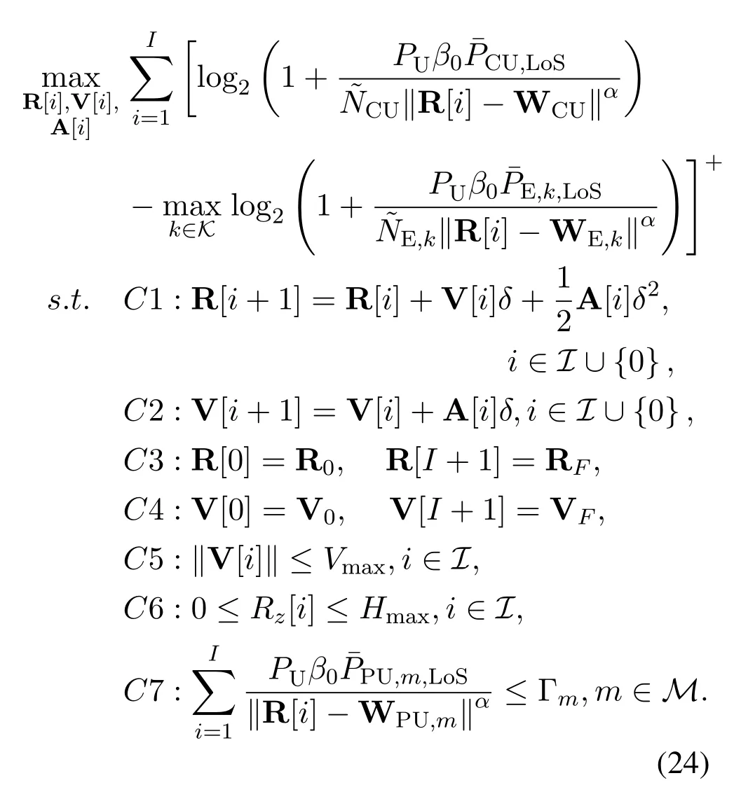
From(24),we have that the optimization problem is non-convex,which is hard for us to directly obtain the optimal solutions.Therefore,we are going to present the following method to handle with this non-convex optimization problem.
III.SOLUTION OF THE SRM PROBLE M
In this section, we firstly introduce slack variances to equivalently transform the optimization problem(24),and then the D.C.approximation approach is applied to turn the non-convex optimization problem into a convex form[31].Next,we present an iterative 3D trajectory optimization algorithm based SRM problem.
Firstly,we note that the objective function and constraint conditionC7 of the optimization problem(24)are non-convex,which results in the non-convexity of the optimization problem (24).To tackle with this non-convex optimization problem,we introduce slack variablesx[i]≥0,y[i]≥0 andzm[i]≥0 into the optimization problem (24).Thus, the problem (24) can be further written by
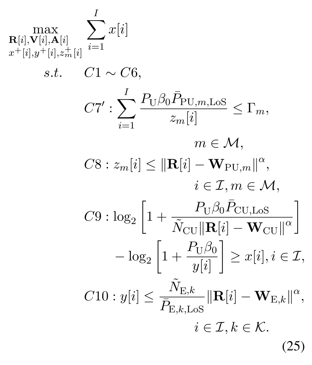
Afterwards, the non-convex optimization problem(25) is approximated into a convex one with the assistance of the D.C.method.From [32]and [33], we have
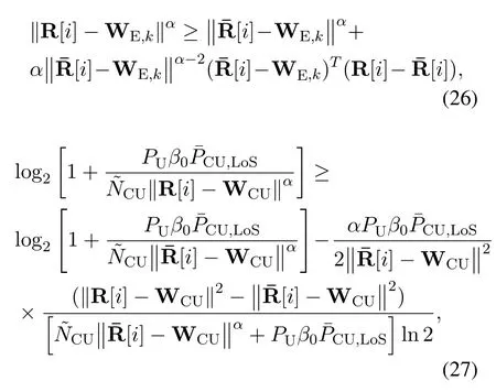
and

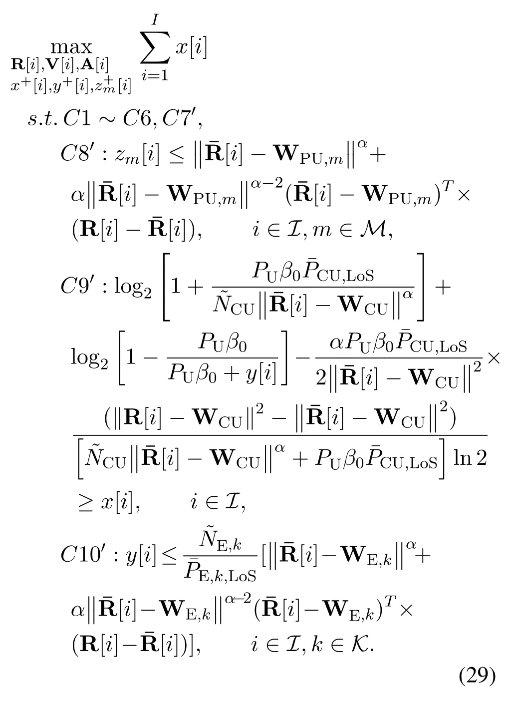
According to[30],it is straightforward to conclude that the problem (29) is convex.Therefore, we can easily figure out the convex optimization problem(29)through the existing convex software tools,e.g.,CVX[34].Then, define Rj[i] and Rj+1[i] are optimal solutions of the optimization problem (30) at iterationsjandj+1, respectively, we put forward an iterative procedure(30)to acquire the near-optimal solution of the problem(25).
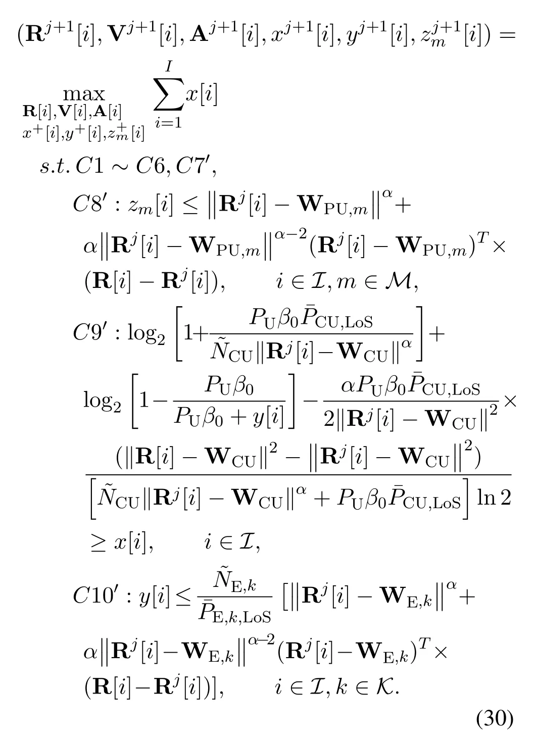
Lemma 1.For any given 3D trajectoryRj[i],the inequalities C8′,C9′and C10′hold in(29).
Proof.Please refer to Appendix.
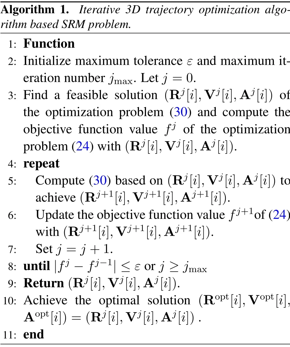
As summarized in Algorithm 1, we present an iterative 3D trajectory optimization algorithm based SRM problem to achieve the near-optimal solution(Ropt[i],Vopt[i],Aopt[i]) of (24).First of all, we initializeε,jmax, andj= 0.Then, the optimal UAV 3D trajectory (Rj+1[i],Vj+1[i],Aj+1[i]) is obtained based on(Rj[i],Vj[i],Aj[i])through utilizing the D.C.approximation approach and the CVX software tool.
Following[35],the computational complexity of the algorithm is related to the number of iterations and the variable size.Since the optimization problem(30)has three 3×I, two 1×Iand oneM ×Imatrix variables,the overall computational complexity of the Algorithm 1 can be expressed by

Algorithm 1. Iterative 3D trajectory optimization algorithm based SRM problem.1: Function 2: Initialize maximum tolerance ε and maximum iteration number jmax.Let j =0.3: Find a feasible solution (Rj[i],Vj[i],Aj[i]) of the optimization problem (30) and compute the objective function value fj of the optimization problem(24)with(Rj[i],Vj[i],Aj[i]).4: repeat 5: Compute(30)based on(Rj[i],Vj[i],Aj[i])to achieve(Rj+1[i],Vj+1[i],Aj+1[i]).6: Update the objective function value fj+1of(24)with(Rj+1[i],Vj+1[i],Aj+1[i]).7: Set j =j+1.8: until|fj −fj−1|≤ε or j ≥jmax 9: Return(Rj[i],Vj[i],Aj[i]).10: Achieve the optimal solution (Ropt[i],Vopt[i],Aopt[i])=(Rj[i],Vj[i],Aj[i]).11: end
whereJdenotes the iteration number required for the Algorithm 1.
IV.SIMULATION RESULTS
This section presents the simulation results to show the superiority of our proposed SRM strategy.The corresponding parameters and values we used in numerical evaluation are given in Table 2.Moreover,the numbers of PUs and Es are respectively considered asM= 4 andK= 2.The constants in(4) as set asA= 10 andB= 0.6.Furthermore,the homogeneous LoS probabilitiesandin (10) and (11) are both set as the values corresponding to the elevation angle of 90◦.The UAV’s origin and destination locations are respectively given by R0= [−300,300,100]Tand RF=[300,−300,100]T[34].It is assumed that the starting and final speed V0= VF= 30(RF −R0)/||RF −R0||,where(RF −R0)/||RF −R0||is the direction from R0to RF[28].Moreover, except for special instructions, the coordinates of the CU, Es and PUs are respectively set as WCU= [−200,−200,250]T,WE,1= [300,300,200]T, WE,2= [200,200,200]T,WPU,1= [−300,0,100]T, WPU,2= [0,−300,100]T, WPU,3= [200,300,100]Tand WPU,4=[100,300,100]T.
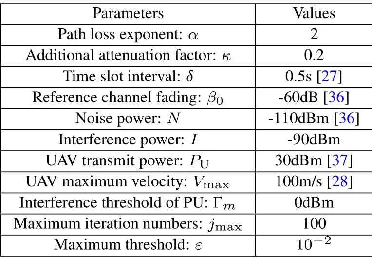
Table 2. System parameters.
Figure 2 demonstrates the convergence performance of the proposed 3D trajectory optimization based SRM algorithms versus the iteration number for different flight timeTand UAV maximum flight altitudesHmax.As observed from Figure 2, the average SR values of the proposed SRM schemes for different flight time and UAV maximum flight altitudes firstly increase,and then converge to their corresponding SR floors.This verifies that the near-optimal SRs would be obtained through applying the proposed SRM algorithms after sufficient iteration numbers.Furthermore,the proposed SRM algorithms tend to converge in a few iteration numbers, which shows the effectiveness of the D.C.approximation method for the proposed 3D trajectory optimization based SRM scheme.
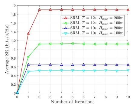
Figure 2. Convergence performance of the proposed 3D trajectory optimization based SRM algorithms for different flight time T and UAV maximum flight altitudes Hmax.
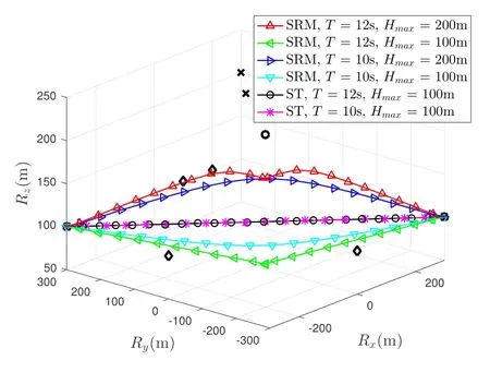
Figure 3. The 3D trajectories of UAV with the proposed SRM and ST schemes for different flight time T and UAV maximum flight altitudes Hmax.The circle, cross and diamond are respectively the locations of CU,Es and PUs.
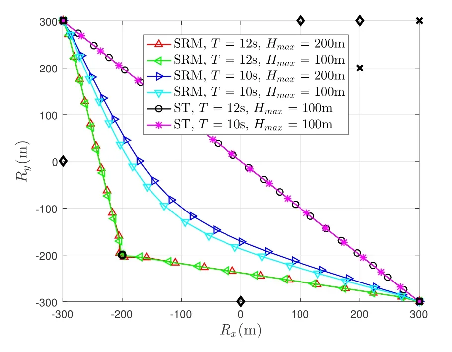
Figure 4. The horizontal flying trajectories of UAV with the proposed SRM and ST schemes for different flight time T and UAV maximum flight altitudes Hmax.
Figures 3,4 and 5 respectively show the 3D trajectories,horizontal flying trajectories and flight altitudes of UAV with the proposed SRM and straight flight(ST) schemes for different flight timeTand UAV maximum flight altitudesHmax.In the ST method,we consider that the UAV flies from R0to RFat a fixed velocity [28].As observed from Figures 3 and 4, the UAV flies towards CU and away from Es to achieve the better SR performance.Moreover, as shown in Figure 4,as the flight timeTincreases fromT= 10s to 12s, the UAV flies closer to CU and farther away form Es in the SRM scheme.What’s more, it is observed from Figure 5 that as the UAV maximum flight altitudeHmaxincreases fromHmax=100m to 200m,the UAV flies higher for the sake of getting closer to the CU.
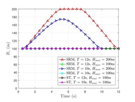
Figure 5.The UAV flight altitudes of the proposed SRM and ST schemes for different flight time T and UAV maximum flight altitudes Hmax.
Table 3 gives the performance comparisons for the proposed SRM and ST schemes with different flight timeTand UAV maximum flight altitudesHmax.It is seen from Table 3 that the average SR values of the SRM schemes are greater than that of the ST method,which means that the SRM strategy is superior to the ST method in the field of the SR performance.Moreover,as the flight timeTgoes on,the security advantage of the proposed SRM scheme over the ST method becomes much more significant,showing the security benefits of consuming more operation time.What’s more,it is noted that for the cases ofT=10s and 12s,the average SRs of the proposed SRM schemes all increase with the increase of the flight altitude, which implies the importance of flight altitude optimization.Furthermore, as observed from Table 3, for the same flight timeT, the average SR of our proposed SRM scheme at maximum flight altitudeHmax= 200m is better than that atHmax= 100m.This is because in our simulation parameters, the height of the CU is set as 250m, and the path loss in the case ofHmax=100m is greater thanHmax=200m.
Figure 6 presents the time-varying UAV speed comparisons for the proposed SRM and ST strategies for flight timesT= 12sand different UAV maximum flight altitudesHmax.As observed,in the SRM scheme, the UAV firstly flies towards the CU with increased speed, then decreases its speed and hovers around the CU over a period of time.At last,the UAV flies to RFat a relatively high velocity.Moreover,the UAV speed of the ST method is always maintained at about 75m/s,as expected.
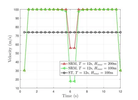
Figure 6.The UAV speed comparisons of the proposed SRM and ST schemes for flight time T = 12s and different UAV maximum flight altitudes Hmax.
Figure 7 illustrates the average SR versus the UAV maximum flight altitudeHmaxof the proposed SRM and ST schemes for different flight timeT.As seen from Figure 7,with the increase of the UAV maximum flight altitudeHmax, the average SR of the proposed SRM scheme improves significantly.What’s more, it is also observed from Figure 7 that SRM schemes outperform conventional ST method in terms of SR performance.
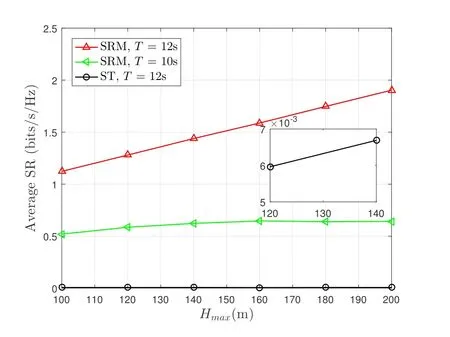
Figure 7. Average SR versus the UAV maximum flight altitude Hmax of the proposed SRM and ST schemes for different flight time T.
Figure 8 plots the UAV 3D flying trajectories of SRM schemes forT= 12s andHmax= 200m with randomly generated locations of CUs, Es and PUs.The CUs, Es and PUs are uniformly and independently distributed in a cuboid of [−300,−300,0;300,300,300].The circle, cross and diamond are respectively the locations of the CUs, Es and PUs.As observed from Figure 8, for the purpose of maximizing the SR of the UAV wireless network,the UAV always flies towards and hovers around the CUs and far away Es.
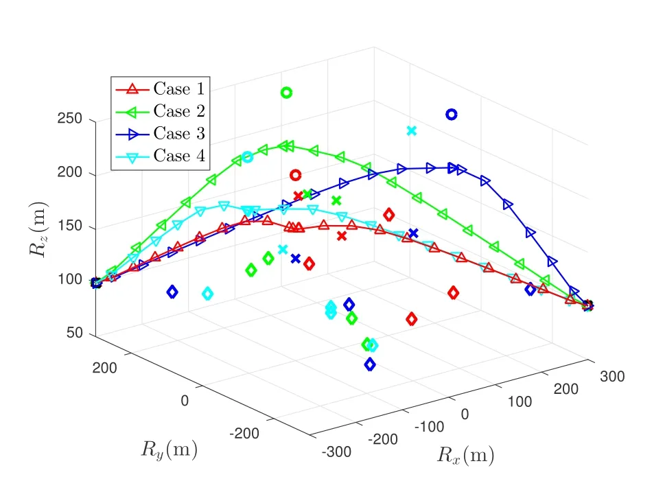
Figure 8. The UAV 3D flying trajectories of SRM schemes for T = 12s and Hmax = 200m with randomly generated locations of CUs,Es and PUs.
V.CONCLUSION
This paper investigated the SRM problem in a UAVenabled cognitive wireless communication network that comprises a rotary-wing UAV,a CU,multiple Es and PUs.The SR of a UAV-enabled cognitive wireless system was maximized through designing the UAV 3D flight path under the constraints of location and speed of the UAV as well as the quality-of-service of each PU.On account of the non-convex SRM problem, we converted the original problem to a convex one with the assistance of the D.C.approximation approach.Then, an iterative 3D trajectory optimization algorithm based SRM problem was proposed to figure out this challenging optimization problem.Simulations were carried out to demonstrate that the SRM approach achieves a better SR performance than the benchmark method.
ACKNOWLEDGEMENT
This work was supported by National Natural Science Foundation of China(Nos.61631020,61671253,62071253 and 91738201),and the Key Project of Natural Science Research of Higher Education Institutions of Jiangsu Province(Grant No.18KJB510031).
APPENDIX
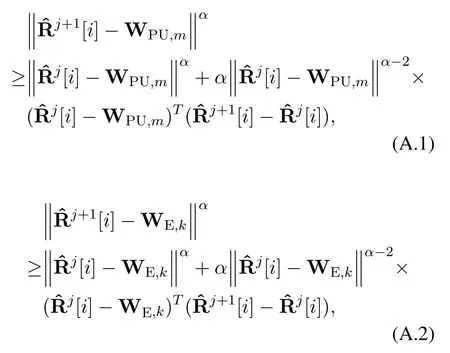
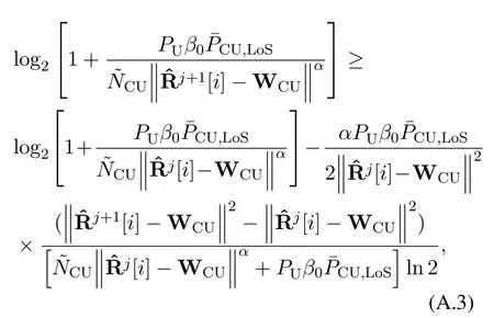
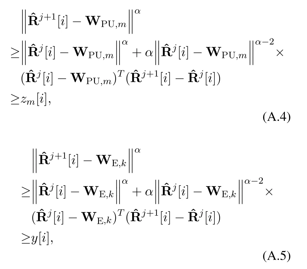
According to(26),(27)and(28),we have
and
and
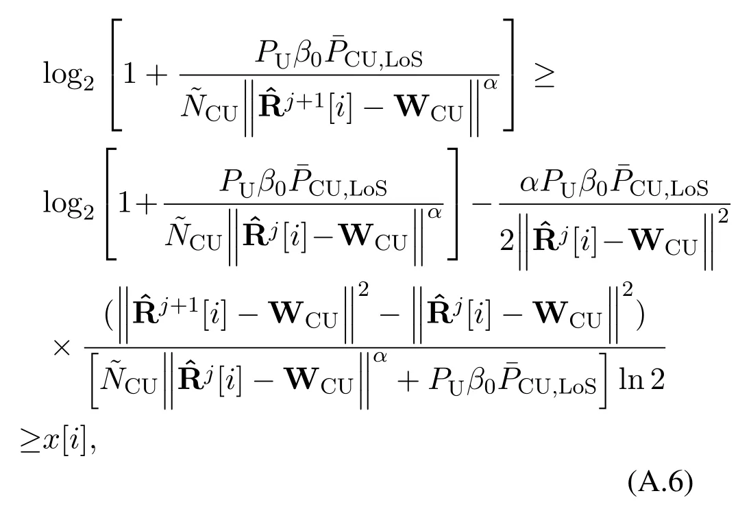
which shows that the feasible domain of the optimization problem(29)is contained in the feasible domain of problem(25).
- China Communications的其它文章
- An Overview of Wireless Communication Technology Using Deep Learning
- Relay-Assisted Secure Short-Packet Transmission in Cognitive IoT with Spectrum Sensing
- Frequency-Hopping Frequency Reconnaissance and Prediction for Non-cooperative Communication Network
- Passive Localization of Multiple Sources Using Joint RSS and AOA Measurements in Spectrum Sharing System
- Specific Emitter Identification for IoT Devices Based on Deep Residual Shrinkage Networks
- Primary User Adversarial Attacks on Deep Learning-Based Spectrum Sensing and the Defense Method

