Spectrum Efficiency Maximization for Cooperative Power Beacon-Enabled Wireless Powered Communication Networks
Wenjun Xu,Wei Chen,Yongjian Fan,Zhi Zhang,Xinxin Shi
1 Key Lab of Universal Wireless Communications,Ministry of Education,Beijing University of Posts and Telecommunications,Beijing 100876,China
2 Hebei Key Laboratory of Security and Protection Information Sensing and Processing,Hebei University of Engineering,Handan 056038,China
3 State Key Laboratory of Networking and Switching Technology,Beijing University of Posts and Telecommunications,Beijing 100876,China
4 Beijing Telecom Planning&Designing Institute Co.,Ltd.,Beijing 100048,China
Abstract: We consider a spectrum efficiency (SE)maximization problem for cooperative power beaconenabled wireless powered communication networks(CPB-WPCNs), where each transmitter harvests energy from multi-antenna power beacons (PBs) and transmits data to the corresponding receiver.For data transmission, both orthogonal transmission, i.e., the time splitting (TS) mode, and non-orthogonal transmission, i.e., the interference channel (IC) mode,are considered.Aiming to improve the system SE,the energy beamformers of PBs, the transmit power,and the transmit time duration of transmitters are jointly optimized.For the TS mode,the original nonconvex problem is transformed into a convex optimization problem by means of variable substitution and semidefinite relaxation (SDR).The rank-one nature of this SDR is proved, and then a Lagrange-dual based fast algorithm is proposed to obtain the optimal solution with much lower complexity.For the IC mode, to conquer the strong non-convexity of the problem, a branch-reduce-and-bound (BRB) monotonic optimization algorithm is designed as a benchmark.Furthermore,a low-complexity distributed successive convex approximation(SCA)algorithm is presented.Finally,simulation results validate the performance of the proposed algorithms,achieving optimality within only 1%∼2% computation time compared to the CVX solver in the TS mode and achieving 98%of the optimal performance in the IC mode.
Keywords: spectrum efficiency; power beacon;WPCN; time splitting; interference channel; wireless power transfer
I.INTRODUCTION
The past decades have witnessed a rapid development of wireless communications, with the prosperity of Internet-enabled smart devices, applications, and services.The massive data transferred among terminal devices demands not only spectrum-efficient wireless networks but also reliable power supply.Recently, energy harvesting (EH) technologies have received significant attention for the potential of prolonging the lifetime of battery-constrained devices[1]by proactive energy replenishment.However, energy harvesting from natural sources faces many challenges.For example, the intermittent, unpredictable,and geographically uneven energy arrivals from natural sources, such as solar and wind, make EH devices difficult to meet the quality of service (QoS)requirements of data transmission [2].Aiming to solve this problem, wireless energy transfer (WET)technologies have been proposed to power communication devices with stable and controllable energy sources[3].Among WET technologies,the near field power transfer such as inductive, capacitive or resonant coupling can provide tenths of watts at the distance of less than a meter.However, the distance of near field WET is strictly limited.Far field WET,i.e.,radio frequency (RF)-based WET is able to support long power transfer distance, but suffers from severe path-loss, which limits the amount of energy that can be transferred [4].Hopefully, the latest advances in wireless communication technologies, such as small cells, massive multiple-input multiple-out (MIMO),millimeter-wave communications, beamforming, and low-powered electronics,pave the way to realistic and practical RF-based WET applications [5–7].Moreover, empowered by RF-based WET, the wireless powered communication networks(WPCNs)emerges,where the communication devices replenish energy completely by WET.
There are mainly two network architectures for WPCNs.The first architecture is based on the hybrid access point (HAP) [8], which serves as both a data access point and an energy access point.In this architecture,wireless powered devices harvest energy from an HAP,and then perform uplink wireless information transfer(WIT)to the HAP using the harvested energy.The advantage of this architecture is the information sharing and hardware reuse in the HAP which benefits from the co-located data access and energy transfer[8].The second architecture is the power beacon (PB)-based WPCN [3], which is the main focus of this paper.Different from the HAPs, PBs do not serve as access point, which makes it more flexible in deployment, without needing to concern the backhaul issues.Therefore,PBs can be densely deployed,effectively shortening the distance between PBs and EH devices and mitigating the path loss problems of wireless energy transfer.Dense deployment of PBs also helps alleviate the doubly near-far problem confronted by the HAP-based WPCNs[9].A multi-point single antenna WET system has been experimentally shown to achieve 15.6% more coverage compared to the single-point WET system[10].
Multiple antenna technologies have been employed to improve the performance of the WPCN.By steering narrow beam to wireless powered devices, it was shown in asingle-PBnetwork the energy transfer efficiency can be effectively improved [11–15].With the deployment of multiple antennas on multi-PBbased WPCNs, the resulting cooperative multi-PB beamforming can provide further gains.It has been shown that the power transfer from cooperative power beacons (CPBs) is more efficient than both the best power beacon power transfer scheme and the nearest power beacon power transfer scheme in a multiantenna multi-PB WET network [16].Furthermore,the superiority of equipping massive antenna arrays in a multi-PB WET network has been validated [17].Note that although the aforementioned works[16,17]have analyzed the fundamental behaviors or performance of multi-PB WPCNs and cooperative WET, it was not considered how to design feasible beamforming power allocation and duration allocation schemes.
In this paper,we consider a cooperative PB-enabled wireless network.With a central controller, multiple PBs equipped with multiple antennas perform cooperative energy beamforming to power the EH transmitters(TXs).The TXs then utilize the harvested energy for data transmission to their corresponding receivers(RXs).The TXs are equipped with two antennas to perform WIT and WET,respectively.Moreover,since we consider the out-band WET as in[18,19],the considered WIT procedure is free of interference from the WET.For the WIT, both the orthogonal and nonorthogonal transmissions are considered, i.e., the TS mode and the IC mode.The main contributions of this paper are summarized as follows.
• We consider a multi-antenna cooperative power beacon-enabled wireless powered communication network, where the cooperative energy beamforming among multiple PBs is adopted to enhance the efficiency of WET.Compared to the conventional WPCN, the CPB-WPCN achieves better SE performance.
• For the TS mode, we propose a semidefinite relaxation(SDR)based optimal resource allocation algorithm.We first prove the equivalence of the semidefine relaxtion by analyzing the rank-one characteristic.Then,a low-complexity Lagrangedual based algorithm is proposed to obtain the optimal solution.Compared to our conference work[20],the newly proposed algorithm achieves a lower computation complexity, and is suitable for more general multi-user case.
• For the IC mode, due to the NP-hardness of this problem,the optimal solution cannot be achieved in an efficient manner.The branch-reduce-andbound (BRB) algorithm is adopted to achieve theϵ-optimal solution to this nonconvex resource allocation problem.Furthermore, for the parallel and asynchronous implementation, a lowcomplexity distributed SCA algorithm is presented, which achieves almost the same SE performance(with only 2%performance loss)compared to that of the optimal one.
Although some works have brought insights into the optimization of cooperative WPCNs [21–26, 20],their models are quite different from the CPB-WPCN model presented in this paper.In[21]and[22],the authors consider cooperative WPCNs in cognitive radio networks.The secondary users acquire transmission opportunities by cooperating with primary users either through providing wireless energy supply or interfering with the eavesdroppers.[21] and [22] do solid work of resource allocation in cooperative cognitive WPCNs.However,they mainly focus on the cooperation among energy harvesting users,which is different from the multi-PB cooperation in this paper.[23]and[24]concentrate on the WPCNs in interference channel, where the imperfect synchronization among PBs is considered.The sum-rate maximization and maxmin fairness problems are investigated in [24] and[23],respectively.However,neither[24]nor[23]considers the multi-antenna PBs, which does not exploit the full beamforming gain.In [25], time and power allocation are jointly optimized to maximize the maxmin throughput and sum throughput in a multi-cell WPCN.However, multi-antenna beamforming is not considered, either.In [26], a sum-rate maximization problem for a multi-user multi-cell WPCN with asynchronous time allocation is studied, where time and power allocation for downlink and uplink are jointly considered.However, [26] also ignores the multiantenna beamforming, which means that the benefits of the cooperative WET are not fully exploited.In our conference paper [20], the optimization of CPBWPCN has been initially investigated.However, the algorithm proposed in[20]is only suitable for the simple two-user TS mode.As will be shown later, the algorithm for the TS mode proposed in this paper applies to general multi-user cases, and the complexity is much lower than the algorithm proposed in [20].The computation time is only 1%∼2% compared to the CVX solver while the computation time in [20]is 41% compared to the CVX solver.Moreover, this paper investigates the IC mode in the CPB-WPCN,which performs better in the sparse deployment case compared to the TS mode.
The rest of the paper is organized as follows.Sec.II presents the system model.In Sec.III, we consider the SE maximization problems of the TS mode,and in Sec.IV,we investigate the SE maximization problems of the IC mode.Simulation results are then provided in Sec.V,followed by the conclusions in Sec.VI.
Notation:We adopt the notation of boldface for vectors a (lower cases) and matrices A (upper cases).CN×Mis theN ×Mcomplex number space.E[·]denotes the expectation.(·)Tand(·)Hdenote the transpose operator and the complex conjugate transpose operator,respectively.Tr(·)is the trace of a square matrix.Rank(·) is the rank of a matrix.For any complex numberx, we use|x|to represent the modulus ofx.The Euclidean norm of the vector x is denoted by∥x∥.AB means that A−B is an Hermitian positive semidefinite matrix, and A≻B for positive definiteness and AB for negative semidefiniteness.For vectors x,y∈Rm,xy means y−x∈For vector x = (x1,x2,...,xM)T,diag(x)means the diagonal matrix diag(x1,x2,...,xM).For real numbery, [y]+represents the operation max{y,0}, andmeans max{min{y,b},a}.
II.SYSTEM MODEL
Consider a multi-antenna CPB-WPCN withNPBs andMTX-RX pairs as depicted in figure 1.Each PB is connected to a constant power supply with the maximum transmit power constraintWith a central controller,PBs can cooperatively adjust respective transmit power and beamformer to improve the system performance.Since PBs do not perform data communication, it is generally difficult to acquire the channel state information (CSI) needed by energy beamforming.Several schemes have been proposed to enable PBs to obtain the CSI at an affordable expense [27, 28].TXs have no fixed energy supplies and need to replenish energy from the radio frequency(RF)signals sent by PBs,while the RXs are assumed to have abundant power supply.This assumption is based on the fact that(a)transmitters are usually lowpower devices with limited battery capacity,e.g.,tiny wireless sensors, and thus WET is benefitial for the deployment; (b) the receivers are usually data fusion centers or sink nodes with more stringent energy consumption requirements which can hardly be powered wirelessly.The TXs are equipped with two antennas,respectively for WET and WIT.The out-band WET mode is assumed, i.e., WET and WIT are performed at different frequency bands, and thus WET does not interfere with WIT.This allows WET of PBs and WIT between TX-RX pairs to be carried out simultaneously.Note that although this assumption may lead to a situation that TXs charge and discharge simultaneously, this problem can be easily solved by equipping TXs with more than one energy storage device(ESD) [29].Also note that this model is applicable as well to the full-duplex WPCN where perfect selfinterference cancellation is available[2,30].Furthermore,similar to the protocol proposed in[2],the transmit power of each TX is subject to both the energy neutral constraint [31] and the peak transmit power constraint.For data transmission between each pair of TX and RX, both orthogonal and non-orthogonal transmissions are considered, i.e., the TS mode and the IC mode.In the TS mode, each TX-RX pair is allocated disjoint time duration, and each TX can adjust its transmit power according to the harvested energy and the allocated time duration.Therefore, both the duration and the transmit power can be optimized to improve the system performance.In the IC mode,all the TX-RX pairs use the same time-frequency resource, and power control is applied to mitigate cochannel interference.
2.1 Energy Transfer
Assume that the energy consumed at the TXs entirely relies on the energy harvested from the PBs during the transmission frame with durationT.Without loss of generality,T= 1 is assumed in this paper.Denote the transmit power of PBnasPnand the channel coefficient between PBnand TXmas hn,m ∈CNp×1,n= 1,2,...,N,m= 1,2,...,M.In this paper,we assume that PBs can obtain perfect CSI between PBs and TX for the tractability of the problem,which is also adopted in [2, 30, 32, 33].In practical system, the CSI acquisition can be implemented by letting TXs periodically report harvested energy level to PBs [27,28].Note that this assumption can be extends readily to the case of imperfect CSI by robust optimization technology as in [34], which we left as our future work.Let wn=∈CNp×1be the transmit beamforming vector of PBnwith∥wn∥2=Pn.Then, the transmitted signal of PBnis

wheresnis the energy signal from PBnwith E[|sn|2] = 1.Although some researches point out that WET using multiple energy beams can provide additional performance gain [35].However, in this paper, we adopt the single energy beam assumption.The reasons are two folds: (a) Rank one beamforming can be easily realized by linear precoders, which is cost-efficient for multi-PB deployment.(b)As will proved in Appendix 1, the increase of energy beams does not lead to performance enhancement in the considered CPB-WPCN system,which means that the single beam is sufficient.By assuming that PBs broadcast the energy signal to all TXs at the same time, the received energy signal at TXm,denoted byym,can be expressed as

wherenmis the additive white Gaussian noise(AWGN) with zero mean and varianceSuppose that the harvested energy from noise power is negligible [36].Then, the total amount of energy harvested by TXmduring one transmission frame can be written as

whereη, 0< η <1, is the energy conversion efficiency.For the convenience of algorithm design and performance evaluation,we firstly adopt the linear energy harvesting model in Sec.III and Sec.IV,whereηis assumed to be a constant(which is widely adopted in papers such as[2],[8,9]).Note that this assumption may lead to performance loss due to the mismatches between theoretic model and practical nonlinear EH components especially when the harvested energy is large.Therefore,in Sec.V,we describe how to extend the model and algorithms for linear EH model into the practical nonlinear EH proposed in[37]and[38].As we will see in Sec.V,this extension is straightforward and uncomplicated.
2.2 Data Transmission
To better evaluate the SE performance of the proposed CPB-WPCN, both the TS mode and the IC mode are considered.In the TS mode, different TX-RX pairs use different time slots to avoid interference,as shown in figure 1(a), while in the IC mode, all TXs transmit simutaneously and carry out interference suppression by adjusting their individual transmit power,as shown in figure 1(b).These two modes represent two typical WPCN scenarios.The TS mode is suitable for the networks where TX-RX pairs are densely deployed in a small area, e.g., cluster-based wireless sensor networks, and the co-channel interference is strong, so that orthogonal transmission must be adopted.Usually there is a centralized controller which dynamically allocates power and time duration for each TXRX pair.On the other hand,the IC mode corresponds to WPCNs with larger coverage area than that of the TS mode.In this scenario, precise synchronization is unavailable but the co-channel interference is mild,and hence power control can be effectively employed.
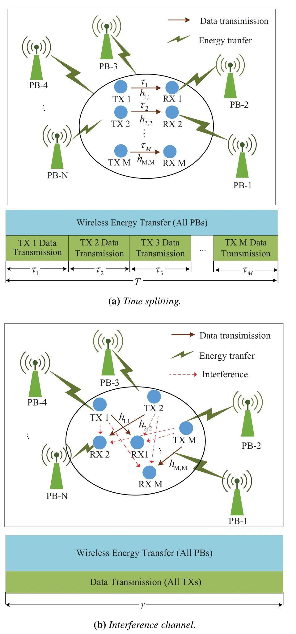
Figure 1. Cooperative PBs-enabled wireless powered communication network.
1) TS mode:Assuming the normalized frequency band,the SE of the TX-RX pairm,denoted byRTSm,is written as

whereτmis the time duration occupied by TX-RX pairmwith=1,gm,mis the channel coefficient of TXmand RXm,andpmis the transmit power of TXm.Thus the total SE of the CPB-WPCN in the TS mode,denoted byRTS,can be calculated as

2) IC mode:the SE of the TX-RX pairmcan be written as

Thus the total SE of the considered CPB-WPCN in the IC mode is calculated as

III.THE TIME SPLITTING MODE
Our goal is to design a spectrum-efficient optimization scheme for the considered CPB-WPCN.The transmit power and beamformer of each PB and the transmit power/time duration for each TX-RX pair are jointly optimized to maximize the system SE.
By defining Xn= wnand Sn,m= hn,mEq.(3)can be rewritten as

Therefore, the optimization of the beamforming vector wnand the transmit powerPnis equivalent to the optimization of the beamforming matrix Xn,n=1,...,N,if Xnsatisfies the rank-one constraint.As a result,the optimization problem can be formulated as
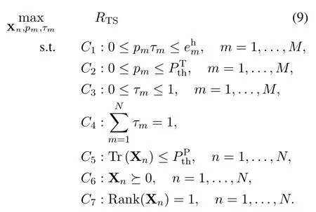
In this optimization problem,C1ensures that the consumed energy of each TX does not exceed the total harvested energy within a time durationT, which guarantees the long term energy neutrality.Note that this constraint is different from classic “harvest-thentransmit” protocol since the energy harvesting and transmitting is conducted simultaneously in out-band WET systems.It is assumed that there is enough energy stored in the battery at the very beginning of the transmission frame.Thus even if there is not enough harvested energy for the first few transmissions in each transmission frame, e.g., the first transmission in the first transmission frame,TXs are still capable of transmitting data.However,C1is still vital for energy neutral operation [31].Also note that since we adopt the multiple-ESD architecture, the harvested energy is accumulated over the whole transmission durationT,which is different form thecausal energyscenario proposed in [30].C2represents the maximum total transmit power constraint of each TX.C3andC4are frame duration constraints.C5is the maximum transmit power constraint of PBs.C6andC7are the positive semidefinite constraint and the rank-one constraint,respectively,which ensure the existence of the optimalcorresponding to
Note that problem(9)is non-convex due to the nonconcavity of the objective function and the nonconvex constraintsC2andC7,which makes it challenging to solve directly.By using variable substitution,problem(9)can be transformed into the following convex optimization problem
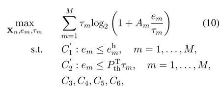
Theorem 1.The optimal rank-one solution to problem(10)is always available.
Proof.See Appendix VII.
Problem(10)is a convex optimization problem and can be efficiently solved by solvers such as CVX[39].Moreover, note that problem (10) satisfies Slater’s condition and the duality gap is zero,which indicates that the low-complexity Lagrange-dual-based solution is possible[40].Specifically,the Lagrange function of problem(10)is
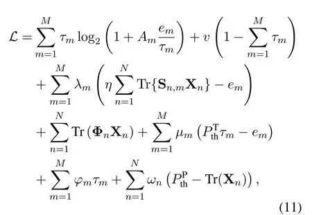
where{λm},{µm},{φm},v,{ωn},and{Φn}are the dual variables corresponding respectively toC3,C4,C5, andC6.Then the dual problem can be expressed as

The coupled relationship between the primal and dual variables can be exploited to design an efficient algorithm for the dual problem (12).The following three theorems show the close relationship between the dual variablevand the other primal and dual variables.That is,by fixing the dual variablev,the other primal and dual variables can be determined uniquely,and based on which we propose a low-complexity algorithm using bisection search.
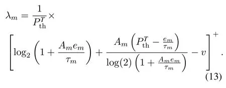
Theorem 2.Given dual variable v, the optimal dual variable λm can be calculated as
Proof.See Appendix VII.
Theorem 3.Given {λm}, the optimal beamformingmatrix{Xn}can be calculated as

where m∗=and νn=νmax{•} means the nor-malized principal eigenvector.
Proof.See Appendix VII.
Theorem 3 indicates that givenv,the optimal beamforming matrix can be uniquely determined.Sincethe optimal harvested energyfor each TX can be determined as well.
Given=1,...,M,the original optimization problem (10) is further transformed to the following concave maximization problem

Theorem 4.Given the dual variable v and the harvested energy{}, the optimal time duration/power allocation for each TX-RX pair can be categorized into four cases as shown in Table 1.

Table 1. Optimal duration/power allocation.
Proof.See Appendix VII.
According to Theorem 4, givenandv, by comparingψmandϕmwithv,the optimal duration/power allocation of each TX-RX pair can be classified into four cases,based on which the optimal duration/power allocation can uniquely be determined.Let us define the optimal time allocation for TX-RX pairmwhen it is categorized into caseA,B,C,andDasandrespectively.By comparing the value of these time allocations withshown in Table 1,the following relationship can be obtained

Let us define the coupling betweenvandτasτm=τm(v), and the total allocated time asτsum(v) =According to Eq.(16),τsumdecreasesasvincreases.Whenvattains the optimal value(defined asv∗),τsum(v) will satisfyτsum(v∗) = 1.As a result, the bisection search method can be adopted to find the optimalv∗.The lower bound and the upper bound ofvare set as

wherem∗=Whenvreachesvupper, it means that allλm=0 according to Eq.(13).
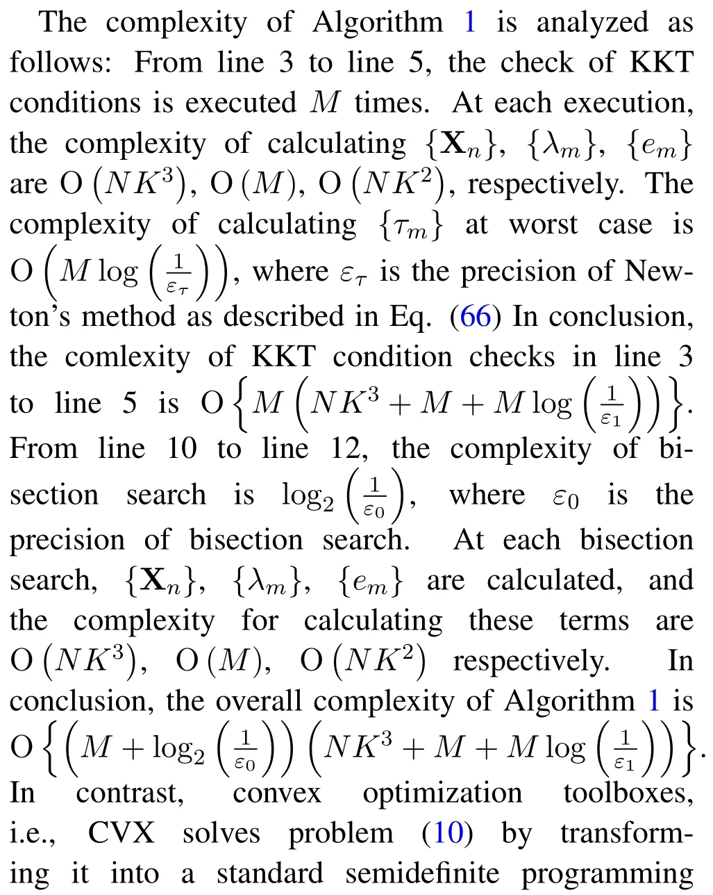
As discussed, the key to solving the dual problem(12) is to find the optimal dual variablev∗.Givenv, the dual variables{λm}can be obtained according to Theorem 2;given{λm},the beamforming matrix{Xn}can be determined according to Theorem 3;given{Xn},the harvested energycan be achieved according to Eq.(8).Furthermore, givenvand,the TX-RX pairs can be categorized asA,B,C, orD, based on which duration and which power allocation that a TX uses.For the optimization of the time duration/power allocation,τsum(v) can be calculated to carry out the bisection search algorithm.In other words,the complex multi-variable optimization problem(10)can be equivalently transformed into a single variable one, i.e., only with respect to the dual variablev,and then it can be solved simply by the bisection search method.The algorithm is summarized in Algorithm 1.And the overview of Algorithm 1 are illustrated in the flow chat figure 2.(SDP) problem.According to [41], the CVX solvers solved problem (10) with a complexity ofwhich is greater than the complexity proposed Algorithm 1,especially when K is large.As will be shown in section V,the execution of Algorithm 1 is much faster than the general CVX solver.
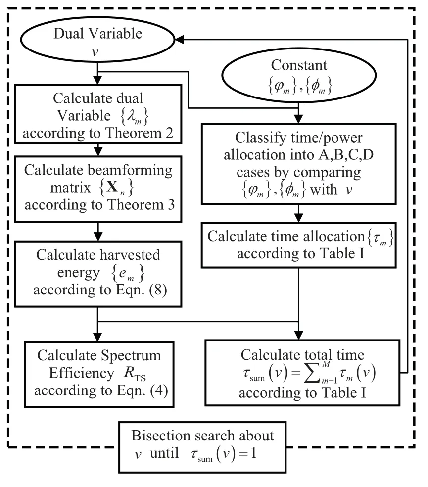
Figure 2. The overview of Algorithm 1.
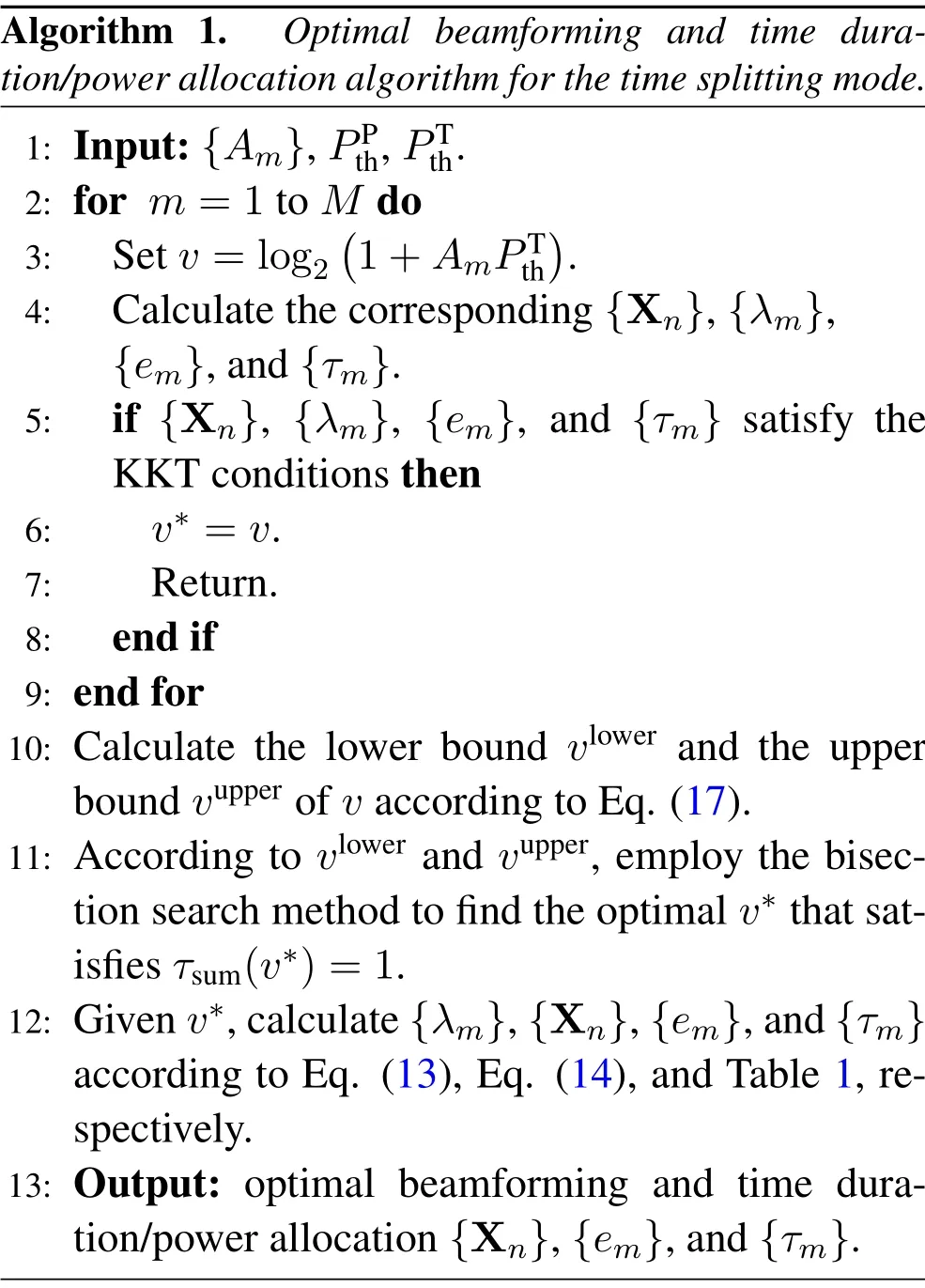
Algorithm 1. Optimal beamforming and time duration/power allocation algorithm for the time splitting mode.1: Input:{Am},PPth,PTth.2: for m=1 to M do 3: Set v =log2(1+AmPTth).4: Calculate the corresponding{Xn},{λm},{em},and{τm}.5: if {Xn}, {λm}, {em}, and {τm} satisfy the KKT conditions then 6: v∗=v.7: Return.8: end if 9: end for 10: Calculate the lower bound vlower and the upper bound vupper of v according to Eq.(17).11: According to vlower and vupper, employ the bisection search method to find the optimal v∗that satisfies τsum(v∗)=1.12: Given v∗,calculate{λm},{Xn},{em},and{τm}according to Eq.(13), Eq.(14), and Table 1, respectively.13: Output: optimal beamforming and time duration/power allocation{Xn},{em},and{τm}.
IV.THE INTERFERENCE CHANNEL MODE
The SE maximization problem for the IC mode is formulated as

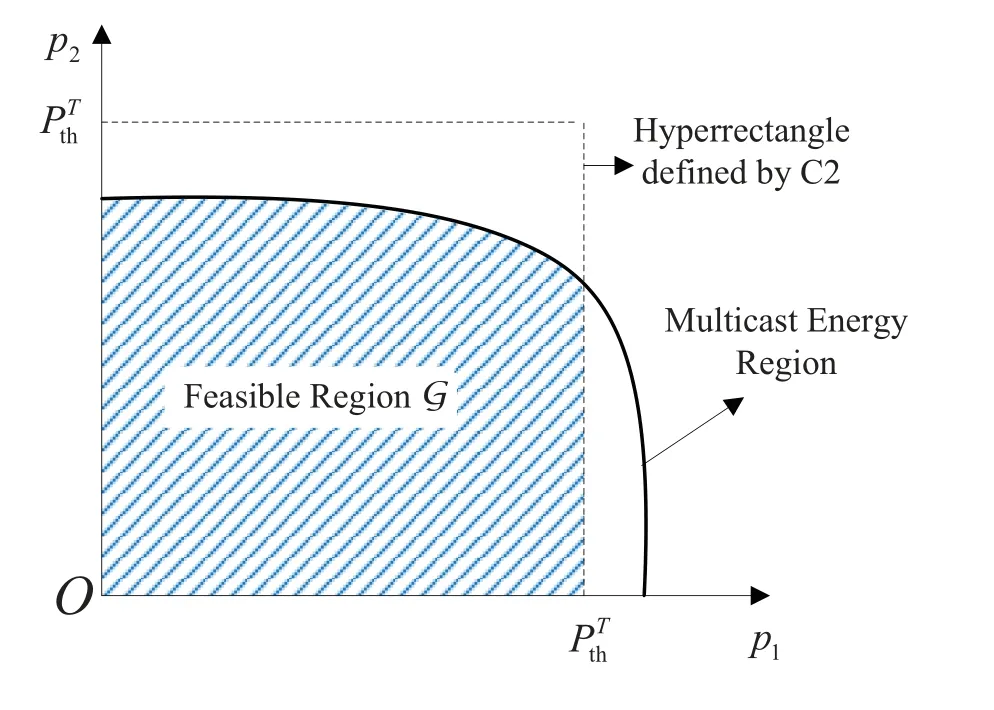
Figure 3. Typical feasible region G for M =2.
where p = [p1,p2,...,pm]TandC8is the total harvested energy constraint, which stems from 0≤pmT ≤,m=1,2,...,M,withT=1.Due to the non-negligible co-channel interference, the objective function of Eq.(18) is strongly non-concave.Since such sum-rate maximization problem in interference channel has been proven to be NP-hard[42],to tackle this problem, we first apply the branch-reduce-andbound algorithm [43, 44] to obtain anϵ-optimal solution as a benchmark.A low-complexity distributed SCA-based algorithm is also presented to achieve a near-optimal solution.
4.1 Branch-Reduce-and-Bound Algorithm for the Interference Channel Mode
Before introducing the BRB algorithm, we first derive the feasible region of the SE maximization problem(18).Define

wheresatisfies Eq.(8),C5,C6, andC7.Gis the intersection of energy region of the multi-cast multicell beamforming problem defined in [45, Corollary 4.10]and the hyperrectangle defined byC2.Figure 3 shows a typical feasible regionGforM=2.It can be observed thatGis a convex set that includes the origin.
Now define the signal-to-interference-plus-noise ratio(SINR)of RXmas

By replacing p withγ,the SE maximization problem(18)can be transformed to

where the feasible region forγis defined as

This leads to the following theorem.
Theorem 5.The feasible region defined byΓEq.(22)is a normal set[44,Definition 4].
Proof.See Appendix VII.
By checking the definition of monotonic optimization,we can find that the transformed problem(21)is a monotonic optimization over a normal set, which can be solved using the BRB algorithm.The BRB algorithm[43]is a global optimization method for monotonic optimization and has been shown its effectiveness in many interesting scenarios of wireless communications[44,46,47].
The basic idea of the BRB algorithm is first to choose a box that contains the feasible region.Then at each iteration,by partitioning,shrinking and reducing the boxes, a set of disjoint boxes are created, together with a tightest lower bound and a upper bound list.The BRB algorithm terminates when the difference between the tightest upper bound and the tightest lower bound is less than a predefined thresholdϵ,and then we obtain anϵ-optimal solution to the problem.
To implement the BRB algorithm,we have to check the feasibility of SINRγ(c), which can be done through the following two steps.
1.Define F with entries

Check if F satisfiesρ[diag(γ(c))F]<1, whereρ(•) represents the spectrum radius of the matrix.Ifρ[diag(γ(c))F]≥1, then according to [48, Lemma 2.1], there does not exist a nonnegative p satisfying Eq.(20), and thusγ(c)/∈Γ.Otherwise, we always have a component-wise minimum nonnegative p(γ(c)) satisfying Eq.(20), where p(γ(c)) can be calculated as

Algorithm 2. Branch-reduce-and-bound algorithm for the interference channel mode.1: Initialization:Set p(0) =pmax m ,the algorithm accuracy ϵ= ϵ0, the line-search accuracy δ = δ0,the initial operating box[0,γmax],the upper bound of the operating box fOupper = RIC(γmax), the existing tightest lower bound fmin = 0, and the set of remaining boxes B ={B1 =[0,γmax]}.2: repeat 3: Select the box with the highest upper bound as the operating box.4: Carry out the branch, reduce and bound procedures,and update the remaining boxes set B.5: Update fmin and the upper bound for each box flupper,Bl ∈B.6: until max(flupper)−fmin <ϵ.7: Output:fmin, RIC(fmin).

with the entries of n calculated as
2.Given p(γ(c)), the feasibility ofγ(c) can be further checked by the following SDP

If the optimal solution to Eq.(25)satisfiesq ≥1,thenγ(c)∈Γ,otherwiseγ(c)Γ.
The BRB algorithm for the IC mode is shown in Algorithm 2.Note that the initial box of the BRB algorithm can be set as [0,γmax], whereγmax(m) =pmax(m)/σ2;pmax(m) is the maximal harvested energy for TXmby settingXn=Sn,m,n=1,2,...,N.
4.2 Distributed SCA Algorithm for the Interference Channel Mode
Although the BRB algorithm guarantees to achieve anϵ-optimal solution, the complexity of the BRB algorithm is unaffordable since it requires exhaustive search over the Pareto boundary of Γ.However, the performance of the BRB algorithm can be set as a benchmark.Since the IC mode is usually adopted in large-scale or heterogeneous WPCNs, a low-complexity distributed algorithm is preferred.
Here we introduce a distributed SCA algorithm that is suitable for parallel implementation.First, definethe objective function Eq.(7) can be alternatively expressed as
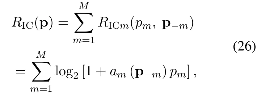
wheream(p−m) is the channel gain-to-interferenceplus-noise ratio(GINR)of TX-RX pairmthat is only related to p−m.With the known power allocation pν,amcan be calculated as

Second, according to the linearization procedure employed in [49–51], by exploiting the Taylor’s expansion ofRICm(p) around the known pν,RICm(pm,p−m) in Eq.(26) can be further approximated as

wherebmcan be regarded as themarginal priceat TXRX pairsmfor generating interference to others[49].bmcan be calculated as
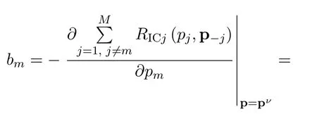
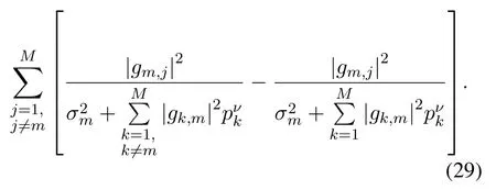
It is observed thatamandbmcan be easily derived from the current interference plus noise power estimated at local receivers asTherefore,amandbmare available at each RX, with the benefits of distributed online implementation.
After such an approximation, the original objective functionRIC(p) can be convexified into the sum ofwhich is only related to variablepmand the known pν.The approximated concave maximization problem can be written as

Note that problem Eq.(30)also satisfies Slater’s condition.Therefore,the Lagrangian function of Eq.(30)can be written as
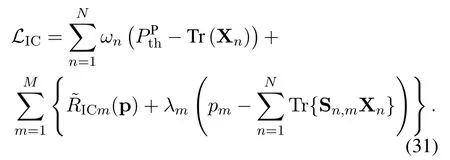
Then the Lagrange dual function of Eq.(30) can be expressed as

with the dual problem being

According to Appendix VII,with givenλm, the optimal Xncan be calculated aswhereBased on this result,the Lagrange dual function can be further expressed as


The optimalλcan be calculated by using subgradient methods[52],with the update ofλmgiven by

wheretis the iteration number andα(t)is the step size.The update of the primal and dual variables are realized by double loops: The Lagrange multipliersλare updated in the outer loop,while given the current value ofthe primal variablespmare distributively updated in the inner loop.
The above method is suitable for the distributed implementation of the proposed CPB-WPCN architecture.However, the TX’s transmit powerpmmay exceed the received power during the iteration,which is physically impractical.To avoid this situation,we add alog barrier penalty functionto the Lagrange dual function Eq.(37) to forcepmto stay within the feasible region.The modified Lagrange dual function is then written as

whereµis a sufficiently small number.The correspondingpmcan be calculated as

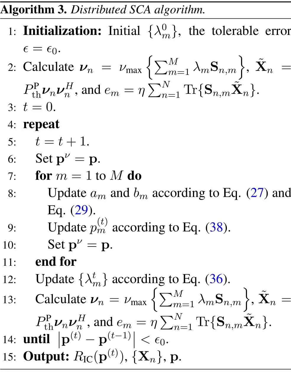
whereDm=ambm,Bm=−ambmem −am+bm −amµ, andCm=amem −bmem −µ.The details of the distributed SCA algorithm are presented in Algorithm 3.
Algorithm 3 can be implemented distributively in the following way.Firstly,the PBs set an initial value ofλand inform the corresponding TXs.At transmission framet, TXmobtains the other TXs’ transmission power p−mfrom PBs.Given p−mand the local estimatedamandbm,TXmadjusts its transmit powerpmaccording to Eq.(38)and reports it to PBs.After all thepmhave been updated in transmission framet,the PBs updateλaccording to Eq.(36).Note that onlyλandp−mare exchanged between PBs and TX-RX pairs at each iteration,and thus the distributed implementation is practicable.
The complexity of Algorithm 3 is analyzed as follows.At each iteration, the value ofam,bmandpmshould be updated once for each TX-RX pair.The complexity of calulatingam,bmandpmis O(M),O(M) and O(1), respectively.The complexity of updatingλmat Line 13 is O(1).The complexity of calculating{Xn},{λm},{em}is O(NK3),O(M), O(NK2).In conclusion, the complexity of Algorithm 3 is O(J(NK3+M2)), whereJis the iteration number of outer loop subgradient method.
V.EXTENSION TO NONLINEAR ENERGY HARVESTING MODEL
In the previous two sections,we have studied the spectrum efficiency optimization problems adopting simple linear energy harvesting model.However,in practical scenarios,the adopted linear EH model is inaccurate and may lead to performance loss due to the mismatches between theoretic model and practical nonlinear EH devices, especially when the harvested energy is large.Therefore, in this section, we extend the aforementioned results to the practical nonlinear EH model.As will be shown below, this extension is straightforward and uncomplicated, which is based primarily on the contents of previous two sections.
According to [53], the output power of a nonlinear EH component is a nonlinear function of the input one,which is expressed as follows:
Algorithm 3. Distributed SCA algorithm.1: Initialization: Initial {λ0m}, the tolerable error ϵ=ϵ0.2: Calculate νn = νmaximages/BZ_252_703_466_733_511.pngimages/BZ_252_733_482_781_528.pngM m=1 λmSn,m images/BZ_252_1014_466_1045_511.png, ˜Xn =PPthνnνHn ,and em =ηimages/BZ_252_702_594_724_639.pngimages/BZ_252_711_559_759_605.pngNn=1 Tr{Sn,m ˜Xn}.3: t=0.4: repeat 5: t=t+1.6: Set pν =p.7: for m=1 to M do 8: Update am and bm according to Eq.(27)and Eq.(29).9: Update p(t)m according to Eq.(38).10: Set pν =p.11: end for 12: Update{λtm}according to Eq.(36).13: Calculate νn = νmaximages/BZ_252_719_1250_749_1296.pngimages/BZ_252_749_1267_798_1313.pngM m=1 λmSn,m images/BZ_252_1031_1250_1061_1296.png, ˜Xn =PPthνnνHn ,and em =ηimages/BZ_252_743_1378_766_1424.pngimages/BZ_252_753_1344_801_1390.pngNn=1 Tr{Sn,m ˜Xn}.14: until■■p(t)−p(t−1)■■<ϵ0.15: Output:RIC(p(t)),{Xn},p.

where

andαm, βm, Mmare constants obtained from measurement data by data fitting tools.Taking the nonlinear EH into account, the optimization model (10) of TS model is modified as
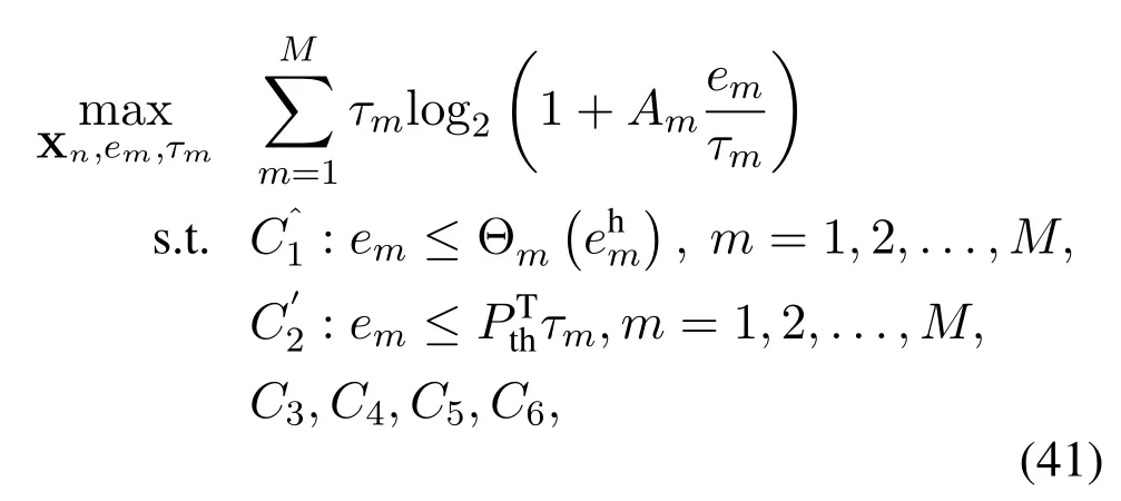
Firstly,reformulate constraintas a difference of convex function

The first term of Eq.(42)is a convex function ofem,which can be lower bounded by its first-order Taylor expansion around a fixed¯emas

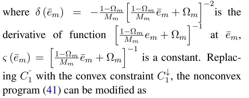
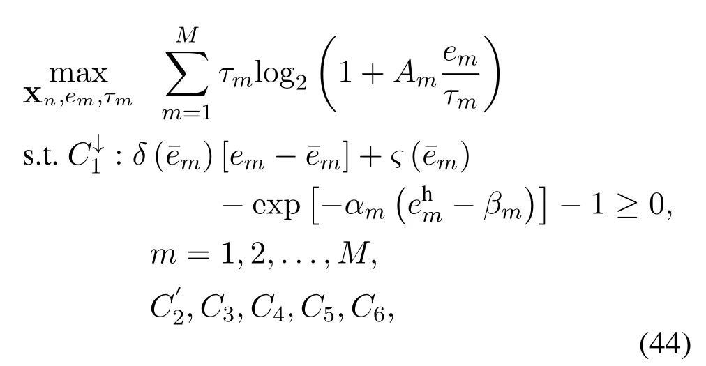
which is a convex problem.The optimum of Eq.(44)can be obtained by standard convex solvers such as CVX.In SCA procedure, we need to successively solve the problem (44) and replacewith the optimal solutionto problem(44).Ifconverges,it returns a suboptimal solution to the nonconvex problem(41).
For IC mode, the extension is straightforward as well.The SE maximization problem for IC mode with nonlinear EH component is written as

Compared to Eq.(18), the only adjustment is the constraintObserved thatis an injective function (i.e., every output harvested power corresponds to a unique input harvested power), a small modification is needed for the proposed BRB algorithm, i.e., replacing the feasible checking problem(18)with the following one
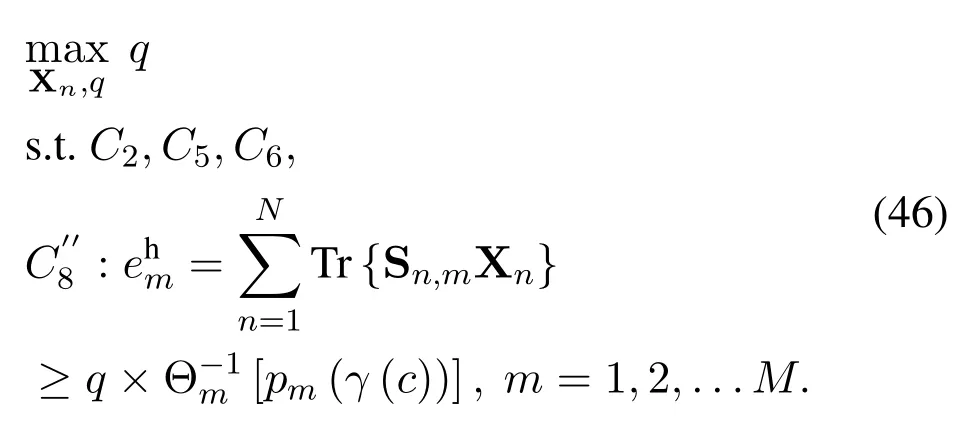
In summary, the algorithm design for TS and IC mode considering nonlinear EH component can be easily obtained by a straightforward extension from the linear one.Therefore, to avoid redundancy, some details are omitted here.
VI.NUMERICAL RESULTS
In this section,numerical results are presented to verify the performance of the proposed algorithm.It is assumed that all channels experience quasi-static flat Rayleigh fading and the channel power gains are modeled asG= 10−3(dXY)−ξ, wheredXYdenotes the distance between nodeXand nodeY, andξis the path-loss factor[8].TX-RX pairs are located in a circular region centered byOwith radius 100 m.N=7 PBs are evenly deployed where 6 PBs are located at the vertexes of a hexagon with centerOand radiusm, and the remaining one is deployed atO.Figure 4 demonstrates the location of PBs and TX-RX pairs.The simulation parameters are summarized in Table 2 unless otherwise stated.Note that the definitions of interference range and transmission range are the same as that in[54],where the transmission range is the maximal distance between TX-RX pairs, and the interference range reflects the maximal distance between RX and the interfering TXs.Note that the interference from TXs out of the interference range will be acknowledged as background noise.Different interference ranges and transmission ranges are set to model different typical scenarios of the TS and IC modes.As a representative, 2 to 4 TX-RX pairs are assumed in the simulations.All simulation results are averaged over 1000 channel realizations.
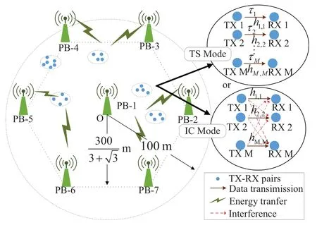
Figure 4. Location of PBs and TX-RX pairs.
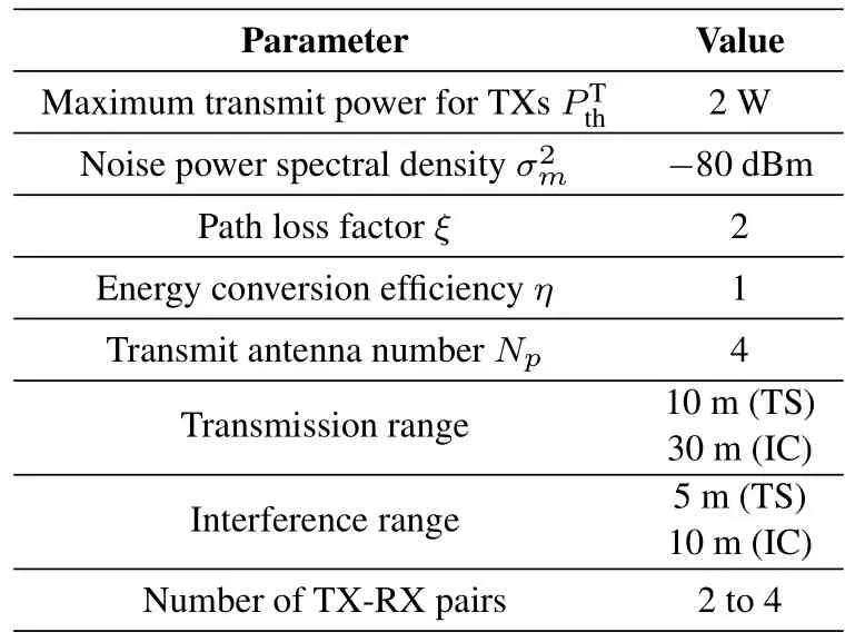
Table 2. Simulation parameters.
6.1 Performance and Complexity Comparisons of the TS Mode
In figure 5, the achievable SE versus the PB’s transmit power constraint of the TS mode under different schemes is depicted.The comparison between single PB with single antenna in [8] and single PB with 4 antennas validates the beamforming gain.Furthermore,the performance of cooperative PBs with single antenna demonstrates the cooperation gain compared to the scheme of cooperative PBs with 4 antennas can achieve more than 150%performance gain compared with the single PB single antenna one,which exhibits the efficiency of the proposed scheme.The improvement of SE results from the higher WET efficiency in the proposed CPB-WPCN.
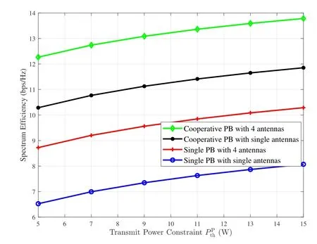
Figure 5. Comparison of spectrum efficiency under various schemes.
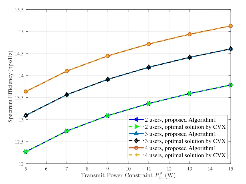
Figure 6. Performance comparison of the proposed algorithm and the optimal solution achieved by CVX solver for the TS mode under different transmit power constraints.
Figure 6 illustrates the performance of the proposed Algorithm 1 compared to the optimal solution to the TS mode, in which the optimal solution is obtained through the CVX solvers in MATLAB [39].Table 3 lists the average runtime of the proposed algorithm divided by that of CVX, where the simulations are performed at MATLAB R2016a based on ThinkVision E1922s with Intel (R) Xeon (R) CPU E5-2603 v3.The proposed Algorithm 1 can achieve almost the same performance as the optimal solution with only 1%to 2%computational time,which verifies both the optimality and the efficiency of Algorithm 1.

Table 3. Complexity comparison of CVX and the proposed Algorithm 1.
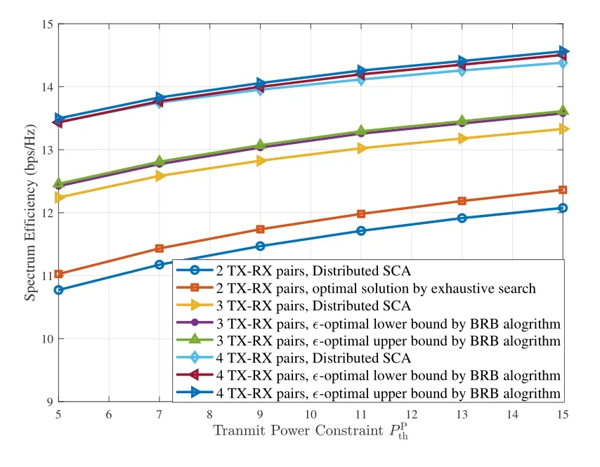
Figure 7. Performance of the BRB and the distributed SCA algorithms under different transmit power constraints in the IC mode.
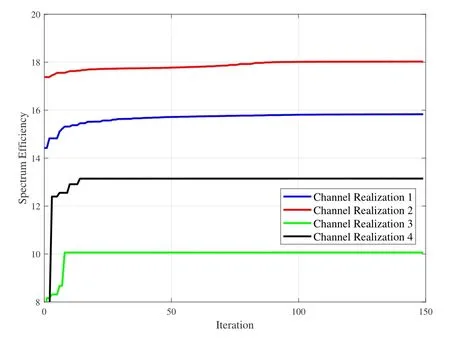
Figure 8. Convergence of the distributed SCA algorithm under various channel realizations.
6.2 Performance Comparisons of the IC Mode
Figure 7 illustrates the performance of both the optimal and suboptimal algorithms in the interference channel mode.The results of the optimal solution achieved by exhaustive search for 2 TX-RX pairs and the BRB algorithm for 3 and 4 TX-RX pairs are provided to serve as benchmark.From figure 7, the distributed SCA algorithm can achieve the near optimal performance, e.g., reaches 98% of the optimal performance in the CPB-WPCN.As the number of TXRX pairs grows larger,the system spectrum efficiency maintains increasing.However, the improvement of spectrum efficiency decreases as the number of TXRX pairs increases.
Figure 8 investigates the convergence of the distributed SCA algorithm under different channel real-izations.It shows the fast convergence of the proposed distributed SCA algorithm.Note that each iteration performs an asynchronous update of the transmit powerpm,and hence only a small amount of calculation and memory is required.
Figure 9 shows the spectrum efficiency for the TS and IC modes under different deployment conditions.The dense deployment scenario corresponds to the one where the interference range and the transmission range are set to 10 m and 5 m, respectively, while in the sparse deployment scenario the interference range and the transmission range are set to 30 m and 10 m,respectively.As shown in the figure,the TS mode outperforms the IC mode in the dense deployment scenario, due to the interference-free orthogonal transmission scheme, while the IC mode exceeds the TS mode in the sparse deployment scenario owing to approaching the non-orthogonal multiuser capacity region.As mentioned previously, this result indicates that the TS mode and the IC mode are suitable for difference WPCN scenarios.
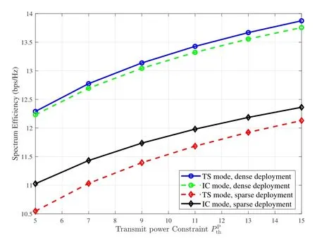
Figure 9. Spectrum efficiency for the TS and IC modes versus different transmit power under different deployment conditions.
6.3 Performance Comparison of the Nonlinear EH Model
Figure 10 compares the energy efficiency for TS mode under linear and nonlinear EH model.To make this a fair comparison, the energy conversion efficiencyηfor linear EH model is set to 0.8.While the parameters for nonlinear EH model areaj=150, bj=0.014 andMj= 0.024 W.The “Linear EH model Ideal”curves stand for the SE calculated by Algorithm 1 under linear EH model, which ignores the mismatches between theoretic model and practical components.While “Linear EH model Practical” curves are the modified SE performance of linear EH model considering nonlinear energy conversion efficiency.As can be seen from figure 10, there is a huge performance gap between the theoretic and practical curves.To narrow this gap, we adopt the SCA algorithm presented in Section V to optimize the resource allocation under nonlinear EH model.The “Nonlinear EH model,optimized” curves show that the proposed SCA algorithm can partially eliminate the impact of nonlinear EH model.However, compared to the single antenna and single PB counterpart, the proposed CPBWPCN scheme still shows huge performance gains,which verifies the superiority of the proposed scheme.
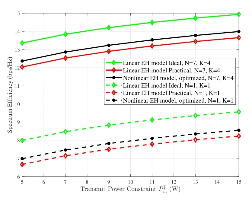
Figure 10. Spectrum efficiency for TS mode under linear and nonlinear EH model for 4 TX-RX pairs.
Figure 11 shows SE performance under linear and nonlinear EH model in IC mode,respectively.All the SE is optimized by BRB algorithm.Similar to the results of TS mode,figure 11 shows severe performance mismatch between theory and reality.In addition, as the transmit power grows larger, the impact of nonlinear EH is greater.This is because that the harvested energy is more likely to saturate in this case.However,the proposed CPB-WPCN scheme still shows huge performance gains compared to the single antenna and single PB scheme.
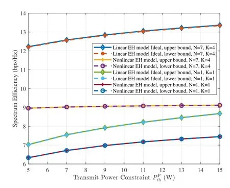
Figure 11. Spectrum efficiency for IC mode under linear and nonlinear EH model for 3 TX-RX pairs.
VII.CONCLUSION
In this paper, we have studied a cooperative multiantenna PB-enabled WPCN.The system SE is maximized by jointly optimizing the beamforming vectors of multiple PBs,transmission duration,and power allocation of multiple TX-RX pairs.Two data transmission modes, namely the TS and IC modes, are considered.For the TS mode, a Lagrange-dual based algorithm is proposed to achieve the optimal resource allocation efficiently with a low complexity.For the IC mode, both optimal and suboptimal solutions are obtained by the BRB and distributed SCA algorithms,respectively.Simulation results validate the superiority of the proposed schemes, which can exploit both the cooperation gain and the beamforming gain.This paper leaves three potential research directions.First, TS mode considering imperfect user synchronization.Second,multi-PB energy beamforming considering channel-estimation and beamforming accuracy trade-off.Third, CPB-WPCN under another orthogonal transmission modes such as Frequency Splitting (FS) mode.All these directions are challenging and may provide further insights into the proposed CPB-WPCNs.
ACKNOWLEDGEMENT
This work was supported in part by National Natural Science Foundation of China(61771066,61629101).
APPENDIX
Proof of Theorem 1
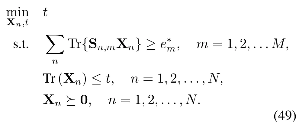
Proof.The proof is completed by showing the following facts: If the optimal solutionto problem (10)satisfies Rank(= 1,n= 1,...,N, then it is also optimal to problem(9).Otherwise,we can always construct an optimal rank-one solutionof problem(10)(which is also optimal to problem(9))from.
To begin with,we show that for each optimal solutionto problem (10), either constraintC′1 or constraintC′2 must be tight.Otherwise,we can always enlarge the optimum of problem(10)by scaling upem.Next,according to whetheris tight or not,the rank ofis analysed in two cases.
First, consider the case that at least one constraintis tight.Denote the index set and the associated dual variable of tightconstraints asKand, respectively.Then according to KKT conditions,we have

whereis the dual variable of constraintC5.Denotethen according to[55,Lemma A.1],we have

Second, consider the remaining case that all ofconstraints are loose, while all ofconstraints are tight.In this case, denoteandas the optimal solution to problem(10).We can construct a rank-one beamforming matrixfrom the following SDP as
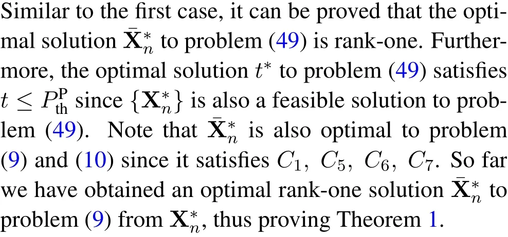
Proof of Theorem 2
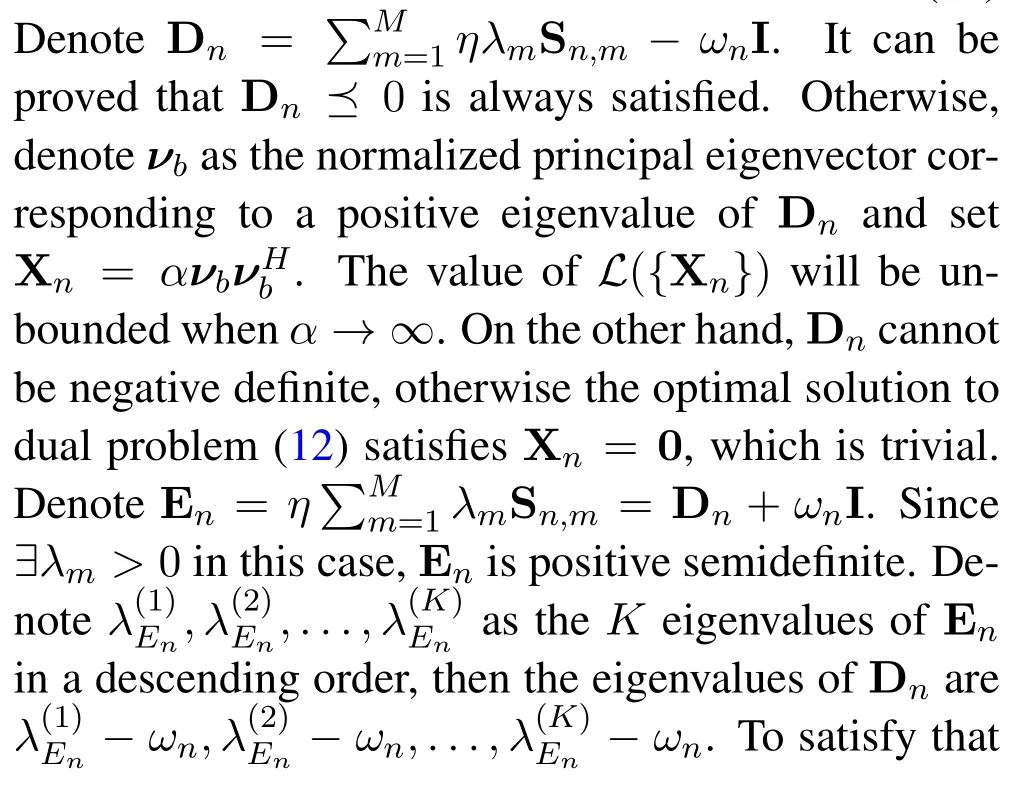
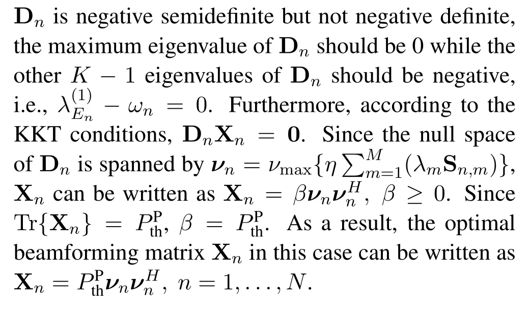
Proof.According to the Karush-Kuhn-Tucker(KKT)conditions,by letting=0,the following equation can be obtained


By combining Eq.(50)and Eq.(51),λmis obtained as
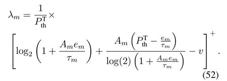
Theorem 2 is thus proved.
Proof of Theorem 3
Proof.The optimal beamforming matrix Xncan be classified into two cases according to differentλvalues.
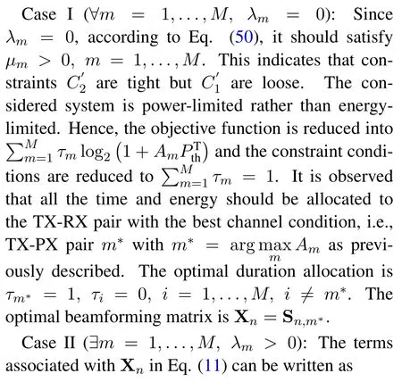
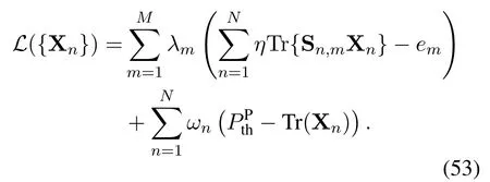
By discarding the constant terms associated with{Xn},Eq.(53)can be equivalently written as

Proof of Theorem 4
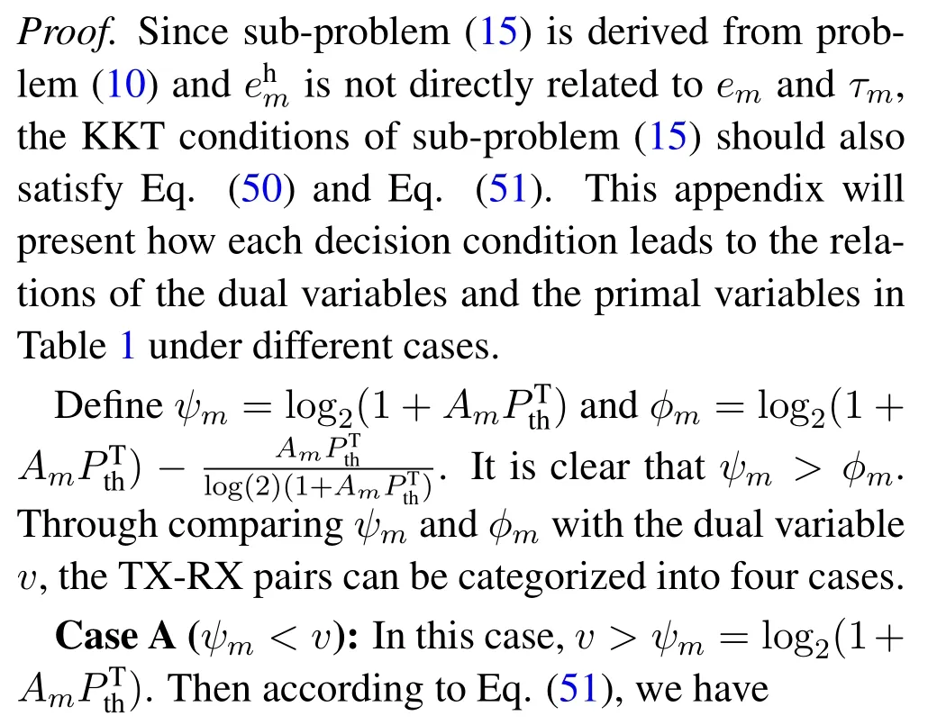
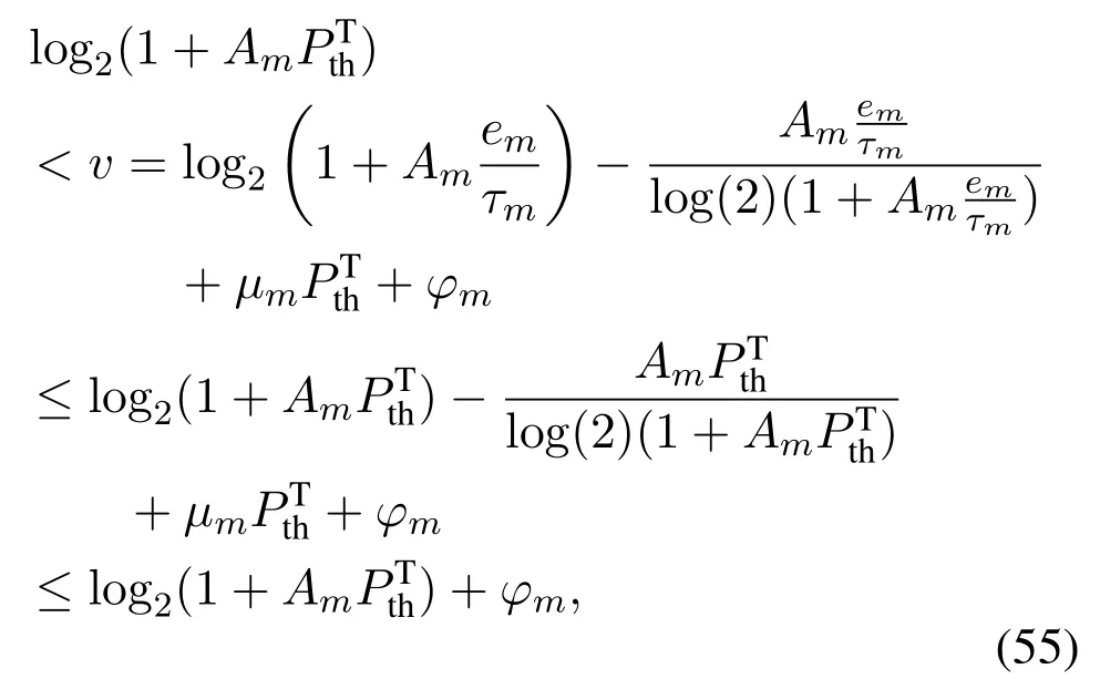
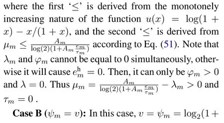


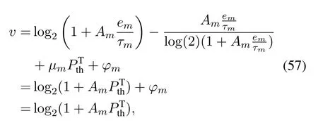
where a contradiction happens.Thusφm= 0.Then according to Eq.(51),we have
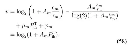


Similar to Case B,we haveφm= 0 andτm >0.By combining Eq.(60)and Eq.(51),we have
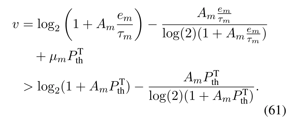
Then it can be further derived that

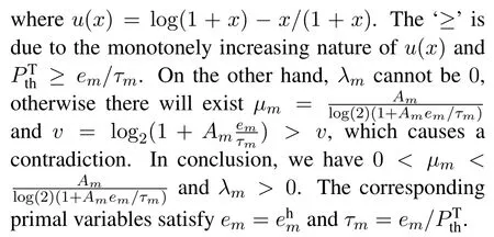
Case D(v ≥ϕm): in this case,we have

Similar to Case B, we haveφm= 0 andτm >0.Besides,µm= 0 should be satisfied,otherwise it can be derived that


Givenvand,τmcan be calculated asτm=, wheres∗is the solution to the following equation

Eq.(66) can be easily solved by Newton’s method[40].Alternatively,τmcan be calculated by the following closed form expression as

wherez=LambertW(−1/(1+vlog(2))).
Proof of Theorem 5
Proof.According to [44, Definition 4], we need to prove that for a feasible SINRγ ∈Γ, anyγ′withγ′ ≤γshould also satisfyγ′ ∈Γ.According to Eq.(24)andγ ∈Γ,we have p(γ)∈G.Then according to[48,Lemma 2.2],we can obtain p(γ)≤p(γ′).SinceGis a convex set including the origin, given p(γ)∈G, any p′ ≤p should also satisfy p′ ∈G.Thus,we have p(γ′)∈G.This proves Theorem 5.
- China Communications的其它文章
- An Overview of Wireless Communication Technology Using Deep Learning
- Relay-Assisted Secure Short-Packet Transmission in Cognitive IoT with Spectrum Sensing
- Frequency-Hopping Frequency Reconnaissance and Prediction for Non-cooperative Communication Network
- Passive Localization of Multiple Sources Using Joint RSS and AOA Measurements in Spectrum Sharing System
- Specific Emitter Identification for IoT Devices Based on Deep Residual Shrinkage Networks
- Primary User Adversarial Attacks on Deep Learning-Based Spectrum Sensing and the Defense Method

