The Dual-Polarized Staggered Stacked Patches Antenna
Xinyu Cao,Jinling Zhang,Hongzhen Yang,Hourong Li
1 School of Electrical and Control Engineering,North China Institute of Aerospace Engineering,Langfang Hebei 065000,China
2 School of Electronic Engineering,Beijing University of Posts and Telecommunications,Beijing 100876,China
Abstract: A new dual-polarized staggered and stacked patches antenna with wide impedance bandwidth and high isolation is proposed.The antenna consists of two groups of radiation patches, in 7 layers, and uses the orthogonal adjacent coupling structure on staggered layer to excite a pair of linear polarization modes.Thanks to the staggered feeder mode, it has increased the isolation performance between ports and compressed the transverse size of the antenna.As a result of the combination of staggered stack-up between the patches and the stepped gradient shape of the main radiating patches, it has effectively expanded the impedance bandwidth of the antenna.The proposed antenna is simulated, fabricated and measured.The staggered feeding structure effectively reduces the cross-sectional area of the antenna, and greatly improves the isolation between feeding ports.The measurement results show that the impedance bandwidths for vertical and horizontal polarization modes are 40.2% (638-960 MHz) and 40.0% (645-968 MHz) respectively when the return loss is lower than -10 dB, and the isolation between feeding ports is better than -30 dB.Meanwhile, the antenna has a stable and symmetrical radiation pattern across the working band, therefore making it suitable to be used as antenna and antenna array element of mobile wireless communication base stations.
Keywords: staggered stacked patches; wide impedance bandwidth;high isolation
I.INTRODUCTION
In recent years, the wireless communication field has presented the momentum of rapid development, particularly new communication business and application technology.It brings new challenges for the design of better components to satisfy higher demands.As one key component, the antenna plays an important role.The design of antenna has to overcome the limitation of bandwidth,rate and size,so as to better match with wireless communications equipment.Additionally, it shall ensure the normal two-way transmission of the frequent communication business.Therefore,it is crucial for the base station antenna unit to realize double polarization,broadband and high isolation[1–4].
At present, there are several methods can be applied to realize the demanded dual polarization modes[5–14], and the most prevailing practice is to directly use microstrip line or coaxial probe to feed radiation patches.This approach was also used in this paper[5–8].Mathew et al.proposed a novel V-shaped slot antenna with single probe-feed[5], which used a single probe to realize three-band dual polarization work.Li.et al.developed a symmetric coax-feed dual polarization patch antenna[6].However,the impedance bandwidth of these antennas does not account to 24%,which is difficult to meet the requirements of modern communication development.Aperture coupling, adjacent coupling and mixed excitation are usually used to achieve dual polarization mode, which have been used in references listed in [9–14].These designs are preferable to other feed modes because of their compact structure and low design complexity.Xie.et al.used two different feed mechanisms to excite the dual orthogonal linear polarization mode[9].One of these two modes is excited by an electrically-coupled probe,and the other one is excited by a magnetically-coupled loop.In reference[10],the authors utilized two symmetric coupling apertures to excite two orthogonal modes.Their results show that the impedance bandwidth has been improved to some extent,but their isolation are not very well, which is only slightly lower than-25 dB,limiting their applications in many fields.Hence, the stacked patch structure is investigated in this paper to obtain good broadband characteristic and high isolation.
In this paper, a new design of dual polarization staggered and stacked patches antenna with wide impedance bandwidth and high isolation is proposed for 690-960 MHz mobile radio communication base station.The antenna is excited by orthogonal adjacent coupled L-shaped microstrip line structure on staggered layer.Two groups of polarized radiation patch element extend along main polarization directions respectively, forming effective barriers between polarization element groups.The isolation between two ports is better than -30 dB.To verify the design,the performance test is conducted to the presented antenna, which shows good consistency with simulated results.
II.ANTENNA DESIGN
The first step is to design a conventional stacked patch antenna, which is an antenna composed of multiple rectangular regular patches placed in layers,with resonant frequency of 690 MHz.The dielectric plate substrate uses FR-4 material,with the thickness of 2 mm,the relative effective permittivityϵrof 4.4,and the loss tangent tanδof 0.02.The number of patch layers and feeding mode are based on bandwidth and radiation performance.The antenna has four layers that are metal reflector (i.e.ground plate), main radiation patch and two guide patches from bottom to top.The antenna is excited by a adjacent coupling L-shaped microstrip line structure under the main radiation patch.These metal patches are supported by a metal bar,where it can also be adjusted for the impedance matching.Figure 1 shows the overall view of the stacked patch antenna, their corresponding coordinates, and size parameters in the design.Figure 1(a) shows the top view of the antenna, the front and the side views of the antenna are shown in Figure 1(b) and 1(c), respectively.
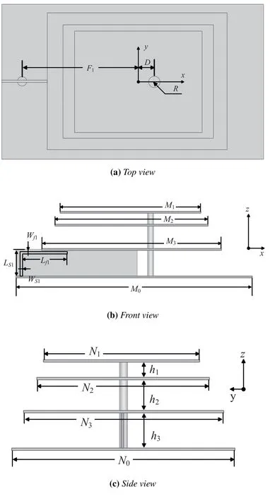
Figure 1. The overall view of the stacked patches antenna.
According to antenna design theory [15], the size parameters of the stacked antenna can be calculated.The detail values are listed in Table 1.Among these parameters,M0, M1, M2, M3, which are the length along the X-axis, correspond to the length of each metal patch;N0, N1, N2, N3, which are the length along the Y-axis,correspond to the width of each metal patch.F1indicates the distance between the feeding port and the center of the patch.Dis the distance between the center of the patch and the supporting metal column, whose radius is R.The adjacent coupled Lshaped microstrip feeding structure, as shown in Figure 1(b),is designed in segments,and the sizes of each segment are determined through simulation optimization, whereLs1andWs1are the length and width of the longitudinal segment of feeder, andLf1andWf1for the transverse segment.

Table 1. Detailed dimensions of the stacked patches antenna(unit: mm).
The impedance characteristics of the antenna model can be verified and analyzed by constructing RLC equivalent circuit.The distribution of zero-pole of impedance corresponded and represented by resonance circuit form [16–19].The equivalent circuit of the stacked antenna is shown in Figure 2.
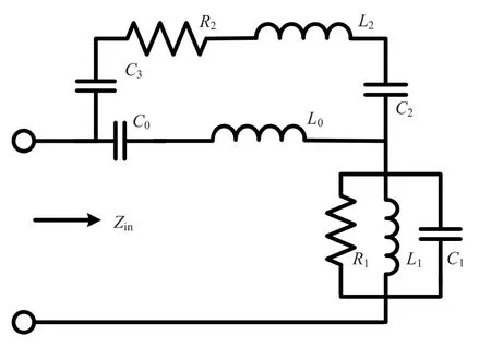
Figure 2. Equivalent circuit of stacked patches antenn.
The resonant working frequency points corresponding to the main radiation patches of antenna can be fitted and equalized by a parallel resonant circuit consisting ofR1,L1andC1in the circuit.The capacitive coupling relationship formed between the lead-in patch and the main radiation patch can be approximately equalized byC2andC3,andL0andL2are equivalent inductances within and between the patches; hence information paths are also formed between multiple patches in the stacked structure.From the perspective of the antenna feed input port, the designed antenna can be deemed as an equivalent circuit formed by cascading two parallel circuit units.The circuit is featured with a multi-resonance working state,which is helpful for the broadband design of the antenna.

Table 2. Detailed dimensions of the ladder shape (unit:mm).
The stacked patch antenna is modeled and its performance is simulated by three-dimensional electromagnetic field simulator software(HFSS).In Figure 3,the simulated return loss is represented by the solid and the dashed lines.The dashed black line presents the result of the conventional stacked patch antenna.It is known that there are two resonant frequencies for the conventional stacked patch antenna.The impedance bandwidths with return loss lower than -10 dB are 10.2% (650-720 MHz) and 8.6% (830-905 MHz) respectively.Two discontinuous passbands are created because the effect of the stacked patch alter the monolithic equivalent circuit form of the patches.This coincides to the multi-resonance working state obtained from the above antenna equivalent circuit analysis.To some extent,it has the function of widening frequency band.However,the antenna frequency band response is far lower than the broadband design requirements of wireless base station.
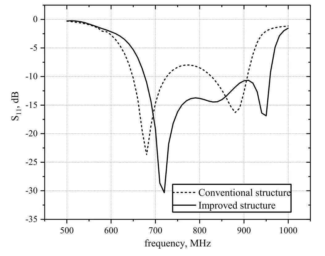
Figure 3. Comparisons of return loss for the conventional and the improving stack patches antenna.
2.1 Bandwidth Broadening Design on the Antenna
As we know, the resonant frequency of the patch antenna is determined by the length of the radiation patch[16].In this antenna design, the widening bandwidth is implemented by changing the resonance length of the main radiation patch.
Figure 4 shows the view of the main radiation patch section of the improved stacked patch antenna,where the dashed black line is the boundary of the conventional stack patch antenna, and the gray circle ring is the position of the metal bars.S1, S2, S3andS4are length and width of the ladder shape.The detailed values are listed in Table 2.
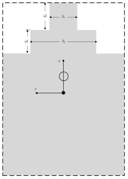
Figure 4. Main radiation patch sections for the improved stack patch antenna.
At frequencies of 690 MHz, 825 MHz and 960 MHz,the surface current distributions of the main radiating patches are as shown in Figure 5(a), 5(b) and 5(c).From the current distribution diagram, it can be observed that the metal copper column loaded by the antenna presents a larger longitudinal distribution of current, which is used to compensate the capacitive reactance introduced between the stacked patches.Apart from the distribution of the local current,it can be found that the surface current on the main radiating patch is mainly concentrated at both ends of the radiating patch,indicating that the antenna works in a half-wave resonant state.Different forms of the current distribution are shown at the step position of each sub-view.Figure 5(a)shows that the current distribution covers the longest step area of the main patch.In Figure 5(b),the current distribution area is retracted to the second step position.In Figure 5(c), the current continues to move downward and is concentrated in the area of the third step position.The current distribution position difference of each subgraph corresponds to different resonant frequencies.Thus we know that the improved antenna with the symmetrical three-step structure formed on the upper part of the main radiation patch generates multiple resonant frequencies in the longitudinal resonance direction, without disturbing original field polarization.The ladder rectangular patch and multi-layer patches can effectively promote the performance of impedance bandwidth.
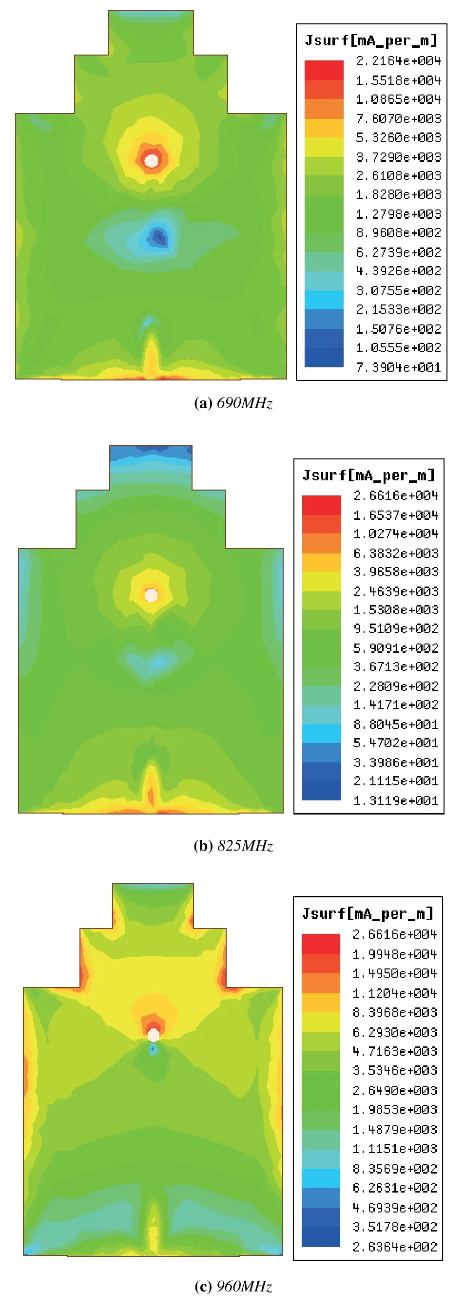
Figure 5. Current distribution diagram of main radiating patch.
It can also be seen from the comparison in figure 3,The solid black line presents the simulated result of the improved stacked patch antenna.The impedance bandwidths with return loss lower than-10 dB is up to 34.8%(675-960 MHz),which is much higher than the conventional antenna.
In order to realize the design of the high isolation dual polarization antenna, the stacked antenna,as a component element of the dual polarization antenna, must have high enough polarization performance.Therefore, the radiation performance of the improved stacked antenna on the E-plane is analyzed.Figure 6 shows the cross-polarization diagram of the antenna at three frequency points: 690, 825, 960 MHz.It can be seen from the figure that the crosspolarization levels of all three frequency points are lower than -50 dB at the radiation center, which is far better than design requirements of radiation crosspolarization.
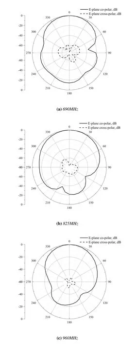
Figure 6. Simulate E-plane radiation pattern of the improved stack patches antenna.
2.2 Dual-polarized Patches Antenna Design
The improved stacked patch antenna is used as the antenna polarization unit.Two groups of antenna units are staggered and stacked, and the proposed antenna prototype is finally determined through analysis and optimization.The geometry of the proposed dual polarization patch antenna is shown in Figure 7.The antenna is set on FR-4 substrate, with the effective permittivityϵrof 4.4 and the thickness of 2 mm.The antenna has a height of 97 mm,with cross section size of 240×190 mm2, as shown in Figure 7(a).These radiation patches are divided into two groups from top to bottom.The top 4 layers are vertical polarization radiation patch group, and its feeding port corresponds to port 1.The lower 3 layers are horizontal polarization radiation group, and its feeding port corresponds to port 2, as shown in Figures 7(b) and 7(c).In each radiation patch group, the bottom floor is the ground plate,and then the main radiation patch and the guide patches stack upwards from the ground plate.These radiation patches in each group are supported by a metal bar,and four dielectric bars support within the group.The metal bar can be adjusted for the impedance matching.The orthogonal feed structure is located under main radiation patches;take the L-shape microstrip line adjacent coupling mode is printed on the dielectric plate which is perpendicular to the radiation patch.According to antenna design theory[15],the size parameters of the proposed antenna can be calculated.The detailed structure parameters of the proposed antenna are listed in Table 3.Among these parameters,M0, M1, M2, M3, M4, M5, M6, which are the lengths along the X-axis,correspond to the lengths of each metal patch;N0, N1, N2, N3, N4, N5, N6,which are the lengths along the Y-axis, correspond to the widths of each metal patch.F1andF2indicate the distance between the feeding port and the center of the patch, respectively.Dis the distance between the center of the patch and the supporting metal column,whose radius isR.Gis the length of the dielectric plate, which serves as the support for the metal ground plate.The structure of two adjacent coupling L-shaped microstrip feeders, as shown in Figure 7(b)and 7(c), are designed in segments, whereLs1, Ls2,Ws1andWs2are the length and width of the longitudinal segment of two feeders,andLf1,Lf2,Wf1andWf2for the transverse segment.
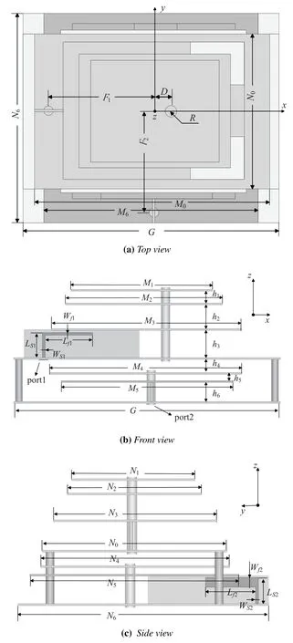
Figure 7. The overall view of the dual-polarized staggered stacked patches antenna.

Table 3. Detailed dimensions of the dual-polarized staggered stacked patches antenna(unit: mm).
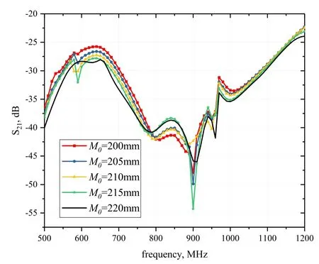
Figure 8. Comparisons of the simulated isolation.
In order to complete the design of the isolation between the antenna ports, the following measures are taken.First of all, the feeding lines are orthogonally placed in the staggered layers, which can effectively increase the distance between different ports, and the horizontal dimension of the antenna can be greatly reduced.Then, these patches of each group are outspreaded in the main polarization direction,which can further enhance the barrier effects among polarized ports.These guide patches have very good guidance effect on the radiation patch group.These measures are good to achieve the effective barrier between the two ports.In order to further ensure the isolation performance between the dual-polarized antenna ports,the parametric analysis is conducted for the structural dimensions of the vertically polarized grouped metal floor as the dual-polarized splitting surface.Figure 8 shows the simulated isolation contrast curves between the two ports,where the different lengths of the ground plate of the vertical polarized radiation patch group are given, that is, different parameters ofM0shown in Figure 7(a).As can be seen from the figure, the different lengths of the metal ground plate correspond to different isolation curves in different colors.These curves are distinguished by different markers.Obviously, with the increase of the parameter value, the isolation performance of the low-frequency and highfrequency areas of the antenna have been relatively improved.In the whole working frequency domain, the isolation curve is smoother, which indicates that the length extension of the splitting surface is conducive to achieving a more ideal isolation effect between ports.Considering requirements of the isolation effect and the antenna size compactness,the length of the ground plate patch is set to 220mm.
III.FABRICATION AND MEASUREMENT RESULT
To verify analysis results, the proposed antenna prototype is fabricated, as shown in Figure 9.And it is measured in the near-field antenna measurement system, as shown in Figure 10.The following analyses are based on the comparisons of the simulated and the measured results.
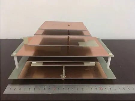
Figure 9. Fabricated antenna.
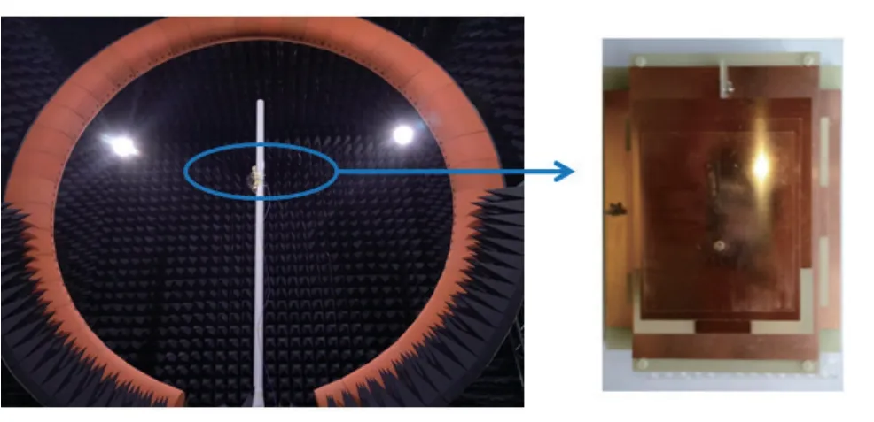
Figure 10. One measured prototype in the near-field antenna measurement system.
The measured results are obtained from a Agilent Technologies E5071C time vector network analyzer and a full automated near-field antenna measurement system.The simulated and measured return loss and isolation are presented in Figure 11.The measured impedance bandwidths with return loss lower than-10 dB are 40.2%(638-960 MHz)and 40.0%(645-968 MHz) for port 1 and port 2, respectively, and both of them cover the desired broaden mobile wireless communication band of 690-960MHz.Compared with the simulation results,the impedance bandwidth of the antenna test results has corresponding broadening in the low frequency band.The reason behind is that there are certain errors in the etching process of the patches during the antenna processing, and at the same time the patches in the same group are connected and fixed by a metal column,which makes the spacing between the patches in the area far away from the center reduced.Therefore, the resonance frequency point decreases slightly.In actual use, it can be considered to increase the dielectric support column to diminish the deviation of structural parameters.The measured results show that the isolation of the antenna is better than-30 dB between the two ports over the whole working band.The measurement results and simulation results are basically consistent.
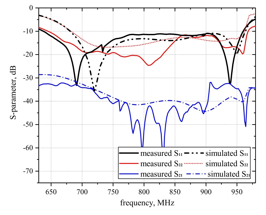
Figure 11. Simulated and measured S-parameter of proposed antenna.
The measured radiation patterns of the proposed antenna at 690, 825, 960 MHz in both E-plane and Hplane are plotted in Figure 12, 13 and 14.It can be seen that the main polarization beam of the radiation is fixed in the z-direction, and the cross polarization levels with the main lobe remains less than -20 dB.Besides,the radiation patterns show good compliance at different frequencies for two ports.
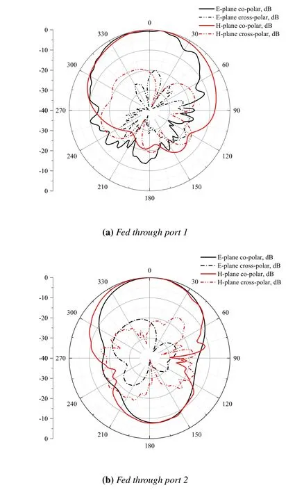
Figure 12. Measured radiation patterns of the proposed antenna at 690 MHz.
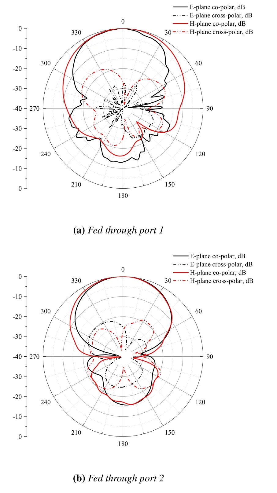
Figure 13. Measured radiation patterns of the proposed antenna at 825 MHz.
The half power beam width (HPBW) of radiation patterns at 690,825,960 MHz for two ports are shown in Table 4.The HPBW measured for two ports is stable and symmetrical under different frequencies.The measured gains for vertical and horizontal polarization is shown in Figure 15, which shows constant trend for the whole working band.Most antenna gain are better than 6.0 and 6.5 dBi for port 1 an port 2, respectively.Thus, the proposed staggered and stacked patches and the orthogonal feeding mode are demonstrated to be valid to realize dual polarization patch antenna with good broadband characteristic,high isolation and good radiation consistency.

Table 4. Measured HPBW of radiation patterns for two ports.
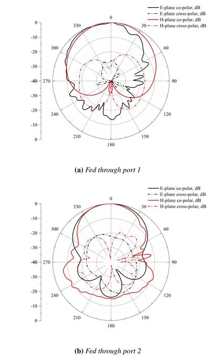
Figure 14. Measured radiation patterns of the proposed antenna at 960 MHz.
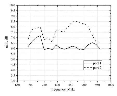
Figure 15. Gains of the proposed antenna.
IV.CONCLUSION
A new dual polarization staggered and stacked patch antenna with wide impedance bandwidth and high isolation is designed, simulated and measured.Two linear polarization modes of the proposed antenna are excited by the orthogonal adjacent coupling structure on staggered layer.The antenna uses the ladder rectangular shaped main radiation patches and the staggered multi-layer patches structure.Measure results show that the antenna achieves the impedance bandwidths of 40.2% and 40.0% with return loss lower than -10 dB for port 1 and port 2,respectively.The antenna has the isolation better than-30 dB between the ports over the whole working band.The measure results with the radiation patterns show good symmetry and consistency at different frequencies for two ports.With features of compact transverse structure,broad band,good isolation and stable radiation gain,the proposed antenna has good application prospects in modern high speed mobile wireless communication system.
ACKNOWLEDGEMENT
This work was supported by Natural Science Foundation of China(Grant 61171051 and 61771063), Planning projects of Hebei provincial department (Grant 15210410),and Research Fund Project of North China Institute of Aerospace Engineering(Grant BKY-2021-13)
- China Communications的其它文章
- An Overview of Wireless Communication Technology Using Deep Learning
- Relay-Assisted Secure Short-Packet Transmission in Cognitive IoT with Spectrum Sensing
- Frequency-Hopping Frequency Reconnaissance and Prediction for Non-cooperative Communication Network
- Passive Localization of Multiple Sources Using Joint RSS and AOA Measurements in Spectrum Sharing System
- Specific Emitter Identification for IoT Devices Based on Deep Residual Shrinkage Networks
- Primary User Adversarial Attacks on Deep Learning-Based Spectrum Sensing and the Defense Method

