Design and analysis of the hydraulic system of the logging harvester head
Kai-lin FENG,Heng-shuo SHI,Su-yong ZHAO,Yang-ming LI
(Shandong University of Science and Technology,Qingdao 266590,China)
Abstract:Logging automation in forestry has become a trend to replace the original manual operation.The hydraulic system of combined logging harvester head was analyzed and designed by parameterization in this paper,and the system was optimized by using load-sensitive pump and multi-channel valve technology.The rationality and reliability of the design was verified based on simulation and analysis of the AMEsim,which provided experience and data support for relevant product development and some design of load-sensitive system.
Key words:Logging automation,Hydraulic system,Load-sensitive,AMEsim
1 Introduction
The research on combined logging machine abroad is earlier and the technology is more mature.However,due to the high technical threshold and price,combined logging machine is less applied in China.The combined logging harvester head has a high degree of automation,and can complete clamping,sawing,lopping,bucking and other processes successively[1].The mechanical structure is shown in Fig.1.Compared with other methods of logging,it has a high efficiency,can be said to be the top electrical and hydraulic control match,greatly save time and labor costs.In this paper,the design and simulation of the hydraulic control system of the combined logging harvester head are carried out to provide design experience for the development of this product and other construction machinery in China.
2 Design and analysis of hydraulic system
As shown in Fig.2,the system adopts load-sensitive pump of rexroth 17 as the power source,and adjusts the working state of the pump to provide the required hydraulic power for the load through feedback signal about pressure or flow rate,so as to reduce the pressure and flow rate loss and realize the purpose of energy saving[2-3].Load-sensitive multi-channel valve of HAWE is adopted as the control and regulation device to integrate connection block,directional valve piece,tail plate and additional block,optimize the system design and ensure several actuators to work as required.
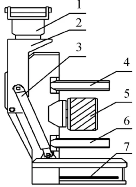
Fig.1 Mechanical structure of combined logging harvester head
2.1 Working process of hydraulic system
The harvester head aims at the bottom of the tree by rotation of the hydraulic motor 1.When the proportional directional valve closes,the motor will continue to move forward at a certain angle due to inertia to cause pressure fluctuation.A pair of pressure relief valve 10 is set to cushioning,reduce pressure changes,and avoid damage to the pipeline and hydraulic motor[4-5].
Useing hydraulic cylinder 4,5,6 to push the lopping knife and roller holding the tree.Setting pilotcontrolled check valve 11 on oil circuit to achieve the purpose of keeping pressure constant for a short time when the directional valve closes.
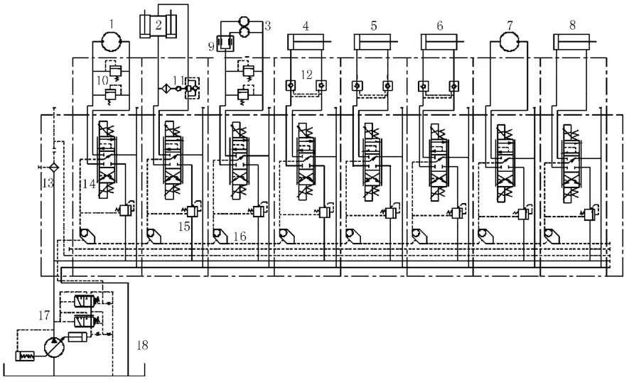
Fig.2 Hydraulic principle of combined logging harvester head
The hydraulic motor 7 drives the chainsaw to rotate and hydraulic cylinder 8 pushes the chainsaw to cut the tree at its root[6].
A pair of inverted hydraulic cylinders 2 push down the tree together,and set a counterbalance valve11 on the return oil line.Controlling the opening area of the throttle orifice by the pressure of the inlet oil line to limit the Falling speed,so as to prevent the tree from falling too fast due to gravity and causing damage to components[7-8].Due to the rigid connection of the mechanical head,a pair of hydraulic cylinders can keep the speed and displacement in sync.
The rollers are driven by a pair of motors 3 that allow the trees to move a certain distance while being held by the lopping knife,and then cut the wood again with a chainsaw.Flow divider and combining valve 9 is set to ensure that the rotation speed of a pair of roller motors is roughly equal.
2.2 Parameter design
In order to facilitate the driver’s observation and operation,the maximum rotation speed of the harvester head does not exceed 10 r/min.Selected the hydraulic motor drive machine with reducer to ensure the low speed stability of rotation.
According to the requirements of logging conditions,cutting speed of chainsaw is about 20 m/s,and reference radius of sprocket R1is 50 mm.The working pressure of the motor of chainsaw is estimated to be about 16 MPa by referring to the working pressure of the fire-fighting hydraulic chainsaw.The speed of the extension and stroke of cylinder of the chainsaw are 20 mm/s and 100 mm,respectively.
The moment balance formula is:

According to 3D modeling,the distance between the rotary center and the stress point L1is 400 mm,and the distance between the hinge point and the rotary center L2is 60 mm.According to the reference“stress balance analysis of oil saw when sawing wood”,the maximum resistance in the sawing normal direction will not exceed 200 N.Therefore,the force of the oil cylinder f can be calculated to be1 333 N by the formula(1).
The speed of tree movement is 0.8 m/s and the radius of roller R2is 0.2 m.
In this paper,the cylinder of lopping knife and roller cylinder are collectively referred to as clamping cylinder.When the clamping cylinder is designed to move at a speed of 50 mm/s,the maximum reaction force for tree is about 8 000 N.
According to 3D modeling,the stroke of the inverted cylinder is 400 mm,and the total extension time shall not be less than 3 s.The load of a single inverted cylinder is a negative and varies,with a maximum value of 17 500 N.
Hydraulic cylinder piston diameter is:

According to formula(2)and the hydraulic design manual,the parameters of cylinder are shown in Table 1.
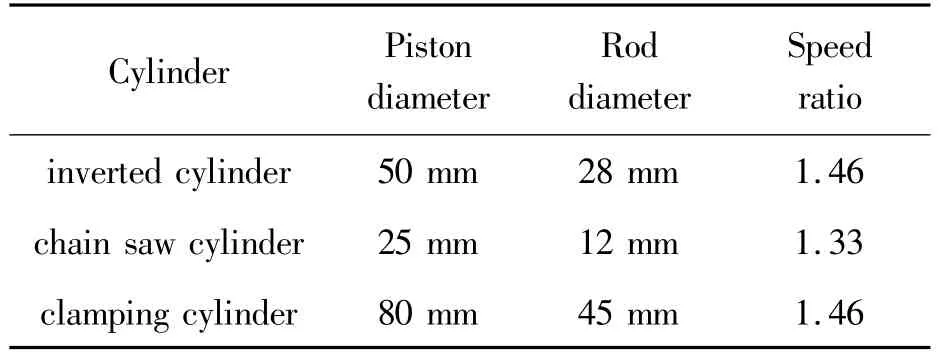
Table 1 Parameters of the cylinder
The speed of the hydraulic motor is

According to formula(3)and the hydraulic design manual,the parameters of motor are shown in Table 2.

Table 2 Parameters of the motor
In the hydraulic system,the maximum flow rate is 78 l/min for drive the two roller motors qmax,so output flow rate of hydraulic pump is:

The pressure loss of the hydraulic circuitΔp is taken as 1.6 MPa,so maximum working pressure of hydraulic pump is:

According to the above calculation,the load sensitive pump A10VSO is selected,with a maximum displacement of 100 mL/r,rotating speed of 910 r/min,rated working pressure of 28 MPa,volumetric efficiency of 0.95.The preset pressure of the flow control valve is 1.4 MPa,and the preset pressure is 28 MPa.
According to the maximum flow and maximum working pressure required by the actuator,the model D7700-3 proportional multi-channel directional valve is selected,and its maximum working pressure and maximum working flow rate are 42 MPa and 100 l/min,respectively.
2.3 Simulation and analysis based on AMEsim
As shown in Fig.3,AMEsim simulation model was established according to the hydraulic circuit diagram,and the model was appropriately simplified in consideration of the similar working conditions of multiple actuators and the computational efficiency of the software.
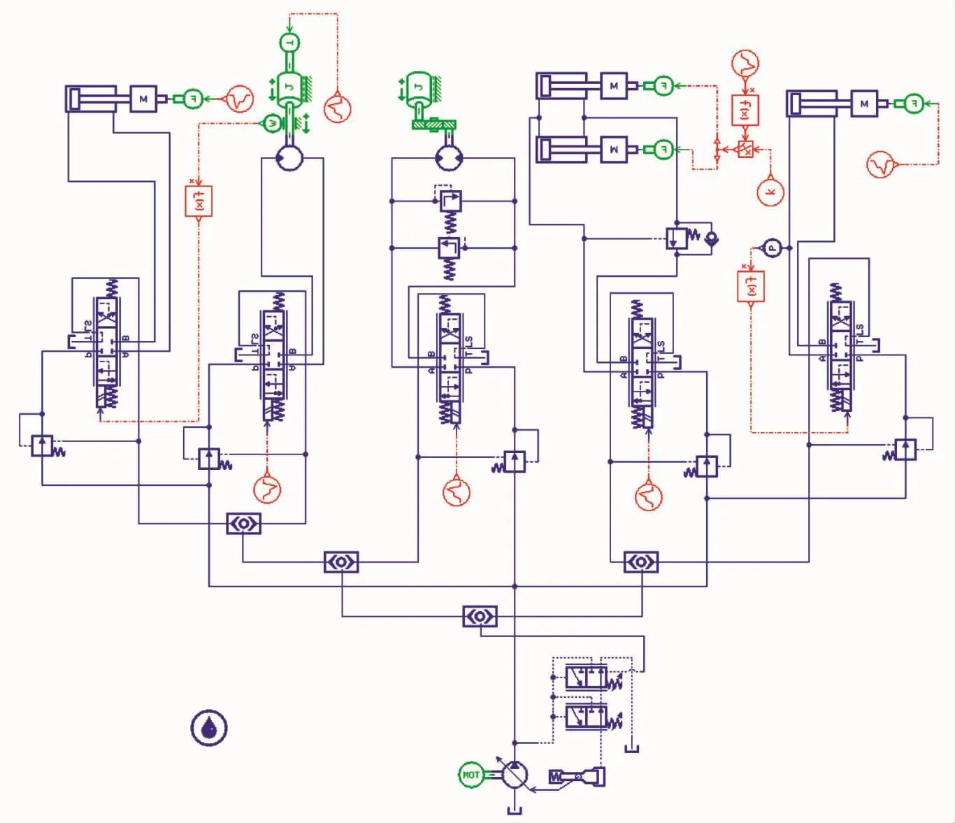
Fig.3 Simulation model based on AMEsim
As shown in Fig.4,when the hydraulic system suddenly starts,the hydraulic impact is reduced by controlling the proportional directional valve to open slowly from 0 to 0.5 s.The pressure difference between port A and port P of the corresponding directional valve is constant at 1.4 MPa,which is consistent with the working principle of the load sensitive pump.From 2.5 to 4 s,the directional valve closes,so the pressure at port P of valve decreases and remains unchanged due to the pump entering the standby condition,and the pressure at port A of valve oscillates slightly until the final stability due to the inertia of the motor.
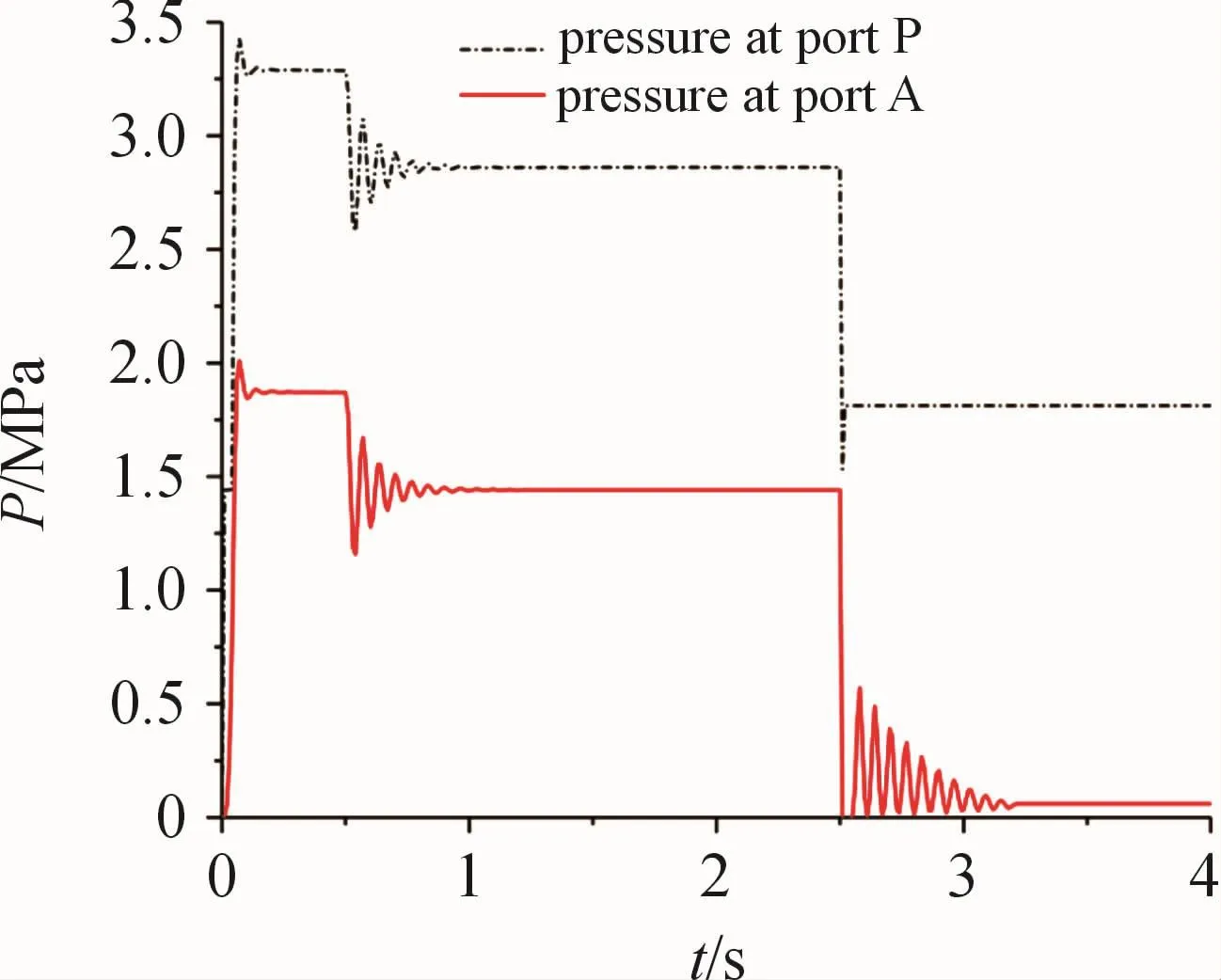
Fig.4 Pressure at port of directional valve of motor
As shown in Fig.5,due to the slow opening of the directional valve,the motor can reach a steady speedof 60 r/min.At 2.5 s,the directional valve is closed and the pressure of the motor return cavity increases rapidly due to inertia,which makes the pressure relief valve open.Due to the action of pressure relief valve,the amplitude and number of pressure oscillations are reduced until the pressure difference between port A and port B of the motor cannot drive the motor to rotate.

Fig.5 Pressure at port and shaft speed of motor
As shown in Fig.6,from 0 to 2.5 s,the motor of chainsaw starts and accelerates to 4 000 r/min under low load.When the speed of the motor reaches 4 000 r/min,the cylinder of chainsaw extends to contact with the trees,increasing the load of the cylinder and the motor of chainsaw.From2.5 to 6 s,when the motor and the cylinder work at the same time,the pressure at the port B of the pump only changes with the pressure at the port A of the chainsaw motor,and the pressure difference is kept at 14 bar,but it has no effect on the pressure change of the cylinder of the chainsaw.The above phenomena accord with the characteristics of load sensitive system,and it is proved that the simultaneous operation of multiple actuators does not interfere with each other because of pressure compensation valve working.
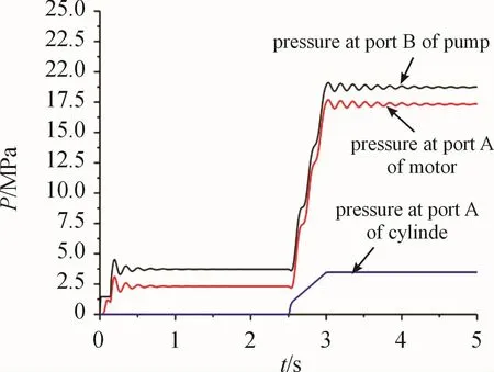
Fig.6 Pressure of pump and actuator
As shown in Fig.7,under the action of the counterbalance valve 10,the inverted cylinder needs 4 s to reach the maximum working stroke of 0.4 m.when the load changes,it can be seen that the velocity of piston rod is almost unchanged.If the counterbalance valve is not installed,due to the weight of the mechanical head and the tree that is held is about 1 750 kg,the speed of piston rod is fast enough to cause accident and damage the components.
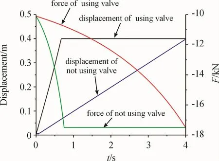
Fig.7 Displacement and force of lnverted cylinder
3 Conclusions
The system uses the load sensitive pump and the multi-way valve,which can meet the purpose of multiactuator working at the same time and saving energy.By analyzing the simulation data based on AMEsim,we can know that the motion of motor and hydraulic cylinder meets the working requirements,and the pressure change is roughly consistent with the actual situation.The design of the hydraulic system is reasonable and can provide data support and experience for the research and development of related products.
- 机床与液压的其它文章
- Lubricating performance of conical spindle distribution in the ball piston pump
- Mechanism analysis and control of asymmetrical digital cylinder
- Reliability analysis and calculationof the drive hydraulic system group of combined transportation
- Reliability analysis for cutterhead hydraulic drive system of remanufactured shield machine
- Application of compound buffer hydraulic cylinder in electro-hydraulic load simulator(EHLS)
- Start-up characteristics of a new electro hydrostatic actuator with an accumulator

