Reliability analysis for cutterhead hydraulic drive system of remanufactured shield machine
Zi-shuai LU,Jing-yi ZHAO,Rui GUO*,He LIU,Bai-lan WANG,Jia-bing HOU
(1Hebei Provincial Key Laboratory of Heavy Machinery Fluid Power Transmission and Control,Yanshan University,Qinhuangdao 066004,China)
(2Key Laboratory of Advanced Forging&Stamping Technology and Science,Yanshan University,Qinhuangdao 066004,China)
(3College of Mechanical Engineering,Yanshan University,Qinhuangdao 066004,China)
(4 Hebei Key Laboratory of Special Delivery Equipment Yanshan University,Qinhuangdao 066004,China)
Abstract:As an important component of green manufacturing,remanufacturing is an effective way to solve the problems of resource shortage and environmental pollution.Compared with other components,the cutterhead of shield machine has a particularly high reliability requirements,so it is necessary to carry out research on the reliability of the remanufactured cutterhead.For the tunneling conditions of shield machine,establish the reliability block diagram and mathematical model of the cutterhead hydraulic drive system,the reliability curve obtained from the simulation is used for reliability prediction and analysis.A fault tree model of the motor module is established and the quantitative analysis of the fault tree is carried to find the key factors of motor’s failure,which provide theoretical measures to improve the reliability of cutterhead hydraulic drive system.
Key words:Remanufacturing,Cutterhead hydraulic drive system,Reliability,Fault tree analysis
1 Introduction
Remanufacturing engineering is an engineering practice aimed at improving the performance of used products guided by the product life-cycle theory.The remanufactured equipment can be restored to its original function and achieve or exceed the performance of new equipment,so the reliability of remanufactured equipment must be no less than new equipment[1-2].Consider the coupling and correlation between the components,the remanufactured equipment reliability research should not be limited to the remanufactured parts reliability,but needs to analyze the whole remanufactured equipment system’s reliability[3].The cutter is driven by variable motors,and shield machine continues to advance while the cutter rotates[4].Therefore,the reliability of cutterhead hydraulic drive system directly determines the overall performance of shield machine.This paper focuses on reliability and troubleshooting of hydraulic drive system of the entire remanufactured cutterhead,and all the key components used in this system are remanufactured component.
2 Reliability model for remanufactured cutterhead hydraulic drive system
The remanufactured hydraulic drive system uses three variable pumps to drive eight variable motors,and its control method is volume speed-regulating circuit.By controlling the cutting speed of cutter to control earth pressures in the soil chamber to make the pressure achieve a balance between chamber and excavation surface so strata disturbance can be reduced and control ground surface settlement[5-6].Because the working performance and hydraulic transmission circuit of each motor module is essentially the same,cutterhead hydraulic drive system simplified to Fig.1.Cutterhead hydraulic drive system mainly includes:variable pump section,variable motor section,variable pump control circuit,variable motor control circuit,braking circuit,accumulator,oil fill circuit and oil supply circuit for control circuit.
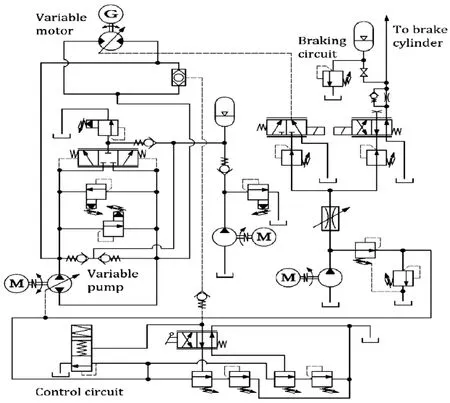
Fig.1 Hydraulic diagram of cutterhead drive system
Combine and simplify circuits according to the function of each circuit:The variable pump control circuit and variable motor control circuit are combined to form variable control section;Adding the accumulator assembly to braking section to achieve its buffering function;Because both the oil fill circuit and control circuit supply circuits are connected to the tank,they are added to tank block diagram,as shown in Figs.2,3 and 4.
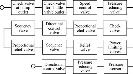
Fig.2 Variable control section

Fig.3 Braking section
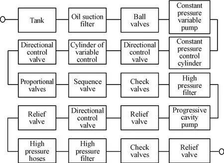
Fig.4 Tank section
High pressure hose in series between variable pump section,variable motor section,variable control section,brake section,and tank section.Establish the entire system block diagram as shown in Fig.5.

Fig.5 Reliability block diagram of cutterhead hydraulic drive system
3 Reliability calculation and analysis of remanufactured cutterhead hydraulic drive system
The actual failure rate of the hydraulic drive system should take the working conditions and applicable conditions into consideration:failure rate of hydraulic components are closely related to the working condition,so the environment factorπEand derating factor πDare set as:πE=30、πD=0.7.The high precision filter is used in cutterhead hydraulic drive system,so the correction factorπCis set to 0.935.
The hydraulic pipes, solenoid valves, variable pumps and motors in this system have been remanufactured.Because the failure rate of remanufactured components is not lower than new components,the failure rate of each component in the remanufactured drive system can be derived by reviewing the literature and other similar engineering hydraulic samples[7-11].
The formula for actual failure rate of cutterhead hydraulic drive system is:

Whereλiis failure rate of system/component.
The reliability expressions for the parallel pump,parallel motor,tank section,variable control circuit,and brake section are equations(2)to(6):

Combine equations(2)~(6)to obtain the reliability expression of cutterhead hydraulic drive system:

The tunneling distance of the shield machine is generally designed to be 10~15 km,and the average forward speed is about 100 mm/min,so the expected maximum service life is1 666.7 h.Set the continuous working time to 2 000 h in simulation,MATLAB simulation was used to obtain these reliability curve shown in Fig.6.
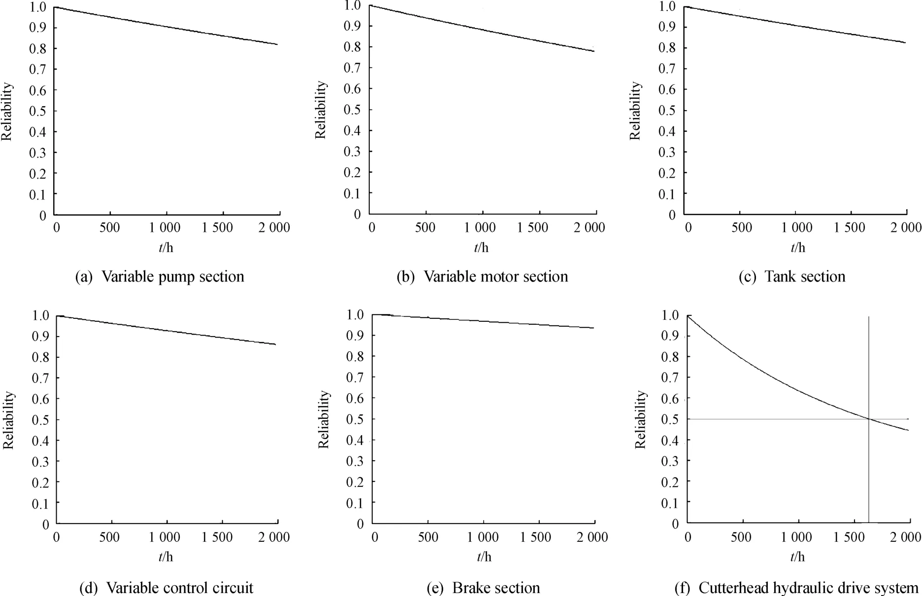
Fig.6 Reliability curve
Fig.6 shows that the overall reliability of the cutterhead hydraulic drive system is 0.5 after 1 666 h continual work according to the estimated time.The highest reliability in this system is braking section and the lowest is motor section.In the following content,we perform fault prediction in the motor section to improve cutterhead hydraulic drive systems reliability,use every bid gap between the tunneling to carry out maintenance of the shield machine to improve system’s reliability.
4 Fault tree analysis of remanufactured cutterhead hydraulic drive systems
The harsh working conditions make motors more susceptible to failure than other components[12],Therefore,motor anomalies are treated as top events in the fault tree.The motor is directly connected to pipelines,variable control cylinders,solenoid valves,check valves,and indirectly to variable pumps through high-pressure hoses,thus the fault tree model is built as shown in Fig.7:x1.Abnormal opening or closing,x2.Serious leakage,x3.Spool failure,x4.Response delay,x5.Leaking hose x6.Blocked pipe,x7.Abnormal noise,x8.Insufficient flow or pressure cannot rise,x9.Variable motor failure.
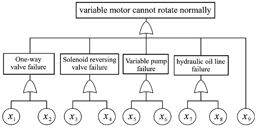
Fig.7 Fault tree model
In the fault tree shown in Fig.7,define top event as T and the next level event as T1、T2、T3、T4,according to the Boolean algebra expression of the OR gate,we can get:

Substitute(8)into T=T1+T2+T3+T4+x9:

There are nine product terms in above equation,so we get nine first-order minimal cut-sets:{x1}、{x2}、{x3}、{x4}、{x5}、{x6}、{x7}、{x8}、{x9}.Each bottom event is a minimum cut-set of the top event,so every bottom event has an adverse effect on the top event.However,since each failure mode does not affect hydraulic system to the same extent,the following section provides a quantitative analysis of each bottom event.
5 Failure mode effects and criticality analysis(FMECA)
FMECA analysis based on the minimal cut-set.The criticality calculation allows a comparison of the extent to which each failure mode affects the top event,so this part uses the estimation method of parsimonious to derive the criticality[13].
Define lethality as,Then the lethality formula for the failure mode in the component is:

Whereαijis frequency ratio of component failure,βijis the influence factor of component failure on the system,λiis component failure rate,t is continuous working time of components.
Determiningβijfrom Table 1[14-15]:
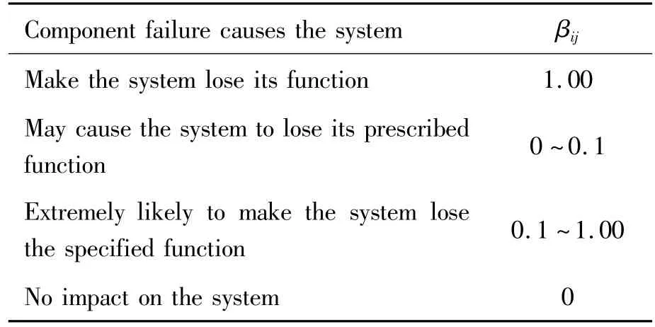
Table 1 The influence factor of component failure
The sum of lethality for the component in the system is:

The failure rates of components associated with variable motors were extracted from literature[7-11],as shown in Table 2:

Table 2 Failure rate of hydraulic components
Setting the system working time to 2 000 h and determineαijandβijto obtain lethality of each component in cutterhead hydraulic drive system,as shown in Table 3.
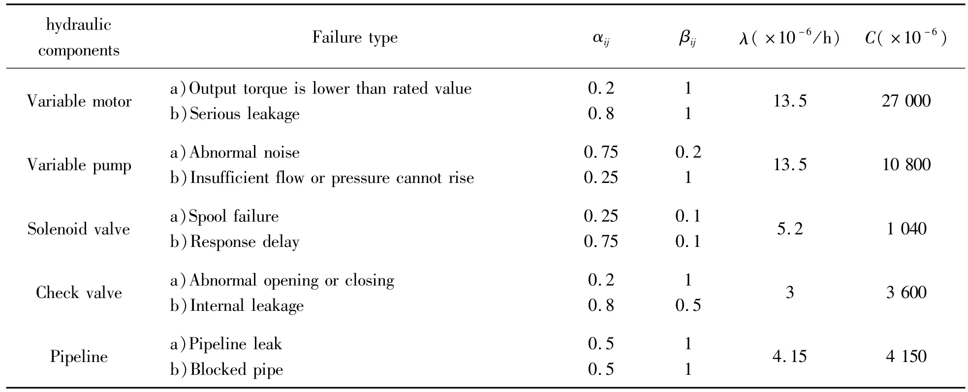
Table 3 Component lethality
From the above criticality calculations,it is clear that motor failure is most likely due to insufficient flow or underpressure in the variable pump;leaks and blockages in the hydraulic lines also have high possibility to cause motor failure;unhealthy check valves and solenoid reversing valves connected to motors can also cause motors to fail.Combined with the system structure to further analyze the reason cause these faults is the harsh tunneling environment,impurities can easily enter the oil,leading to blockage of the oil circuit and causing the action of the check valve and solenoid valve stall,resulting in insufficient oil pressure into the variable oil cylinder,finally causes the torque of the motor to be lower than the rated value.
6 Conclusion
Conclusion of reliability analysis shows that reducing the number of series links in the system,using more integrated components,and using cleaner hydraulic fluid can effectively improve the reliability of remanufactured hydraulic systems.In the whole cutterhead hydraulic drive system,the motor is the most problematic part,through the motor fault tree analysis and component lethality calculation,it is found that the variable pump and hydraulic line are most likely to cause motor failure.Therefore,the design is based on the selection of highly reliable and well-known hydraulic components,the pump’s condition is monitored during operation,and the hydraulic line is replaced and cleaned regularly.The study results provide guidance for improving system reliability and reducing system failure rates.
- 机床与液压的其它文章
- Lubricating performance of conical spindle distribution in the ball piston pump
- Mechanism analysis and control of asymmetrical digital cylinder
- Reliability analysis and calculationof the drive hydraulic system group of combined transportation
- Application of compound buffer hydraulic cylinder in electro-hydraulic load simulator(EHLS)
- Start-up characteristics of a new electro hydrostatic actuator with an accumulator
- Research on dynamic characteristics of vehicle shifting buffer valve

