Start-up characteristics of a new electro hydrostatic actuator with an accumulator
Xiao-xia HAN,Jian XIE,Yong-bao FENG,Zhen-xin HE,Liang LI,Xiao-ling WEI
(Rocket Force University of Engineering,Xi’an 710025,China)
Abstract:Electro hydrostatic actuators(EHAs)are widely used in aircrafts and robotic systems,and their application is gradually progressing toward large mechanical equipment.In this paper,a new structure wherein an accumulator is attached to the piston-side of the EHA is proposed,which is used to achieve rapid start-up under noload.In addition,a new parameter adaptive control method(PACM)is proposed to allow the accumulator to absorb the pulsation of the system pressure and flow rate in the best state when the external load is suddenly applied or changed.The mathematical models of EHA and PACM are established.The feasibility and validity of the proposed structure and PACM are then demonstrated.The simulation results demonstrate that the start-up time of the EHA with the conventional hydraulic structure is 62.8 s,whereas that of our proposed EHA equipped with an accumulator is2.1 s,which shortens the EHA start-up time by 96.6%.The accumulator with PACM can reduce the pressure pulsation by 31%,when the external load of 5 000 N is applied.Moreover,the flow rate curve is excessively smoother and the PACM parameter can be conveniently adjusted according to specific working conditions.
Key words:Electro hydrostatic actuator,Rapid start-up,Accumulator,Parameter adaptive control
1 Introduction
Electro hydrostatic actuators(EHAs)have been proposed for the concept of multi-electric aircrafts,which incorporate motors,pumps,and actuators(hydraulic cylinders)in a single closed system[1-8].In contrast to traditional,centralized hydraulic systems are more superior because they are self-contained,more compact,and lighter.EHAs have been used to replace hydraulic servo actuator products and successfully implemented on aircrafts and robots to improve system performance[9].Advancements in large scale machineries focuses on miniaturization,integration,intelligence and high pressure,such as the hydraulic leveling system.Owing to their high integration capabilities,EHAs can overcome many shortcomings such as leakage,greater pressure loss associated with the centrally supplied hydraulic systems of large equipment[10].
There have been many studies on the modelling and control of EHAs.Sakaino et al.[11]proposed a feed forward module and interference observer to suppress the static friction and the modeling error of the internal leakage.Considering the uncertainty caused by the nonlinear behavior and dynamic characteristics of EHAs,Habibi et al.[12-13]employed the model identification technique to derive a range of values for unknown parameters such as the cylinder leakage coefficient.They verified the model via an open loop testing of the system,and the results showed that derived model was consistent with the response measured atlow to medium excitation frequencies.Rabbo et al.[14]studied the effect of variations in volume displacement and motor torque on the pressure and hydraulic motor speed.Kang et al.[15]designed a state feedback controller by combining the dynamic pressure feedback and variable gain control strategy through a simulation analysis to improve system dynamics and static performance.Zhang et al.[16]proposed a double fuzzy sliding control method with linearized feedback optimal sliding surface.This method linearized the nonlinear model of EHA and obtained the linear switching function via the optimal control theory.Gao et al.[17]used the PID algorithm to control the nonlinear problem associated with EHAs.Navatha et al.[18]employed a PID controller for the dynamic analysis and position tracking and control of the EHA system.The adjustments in the PID controller were made using the Ziegler Nichols method.The PI,proportional differential(PD),and PID controller responses were investigated.The results show that the PD controller achieves the best response.Cho et al.[19]solved the position tracking problem associated with high performance EHAs by a simple adaptive control method.Kim et al.[20]proposed an adaptive back-stepping control scheme to address the uncertainties in EHA systems.
The aforementioned literature review shows that the research on the control strategy of EHAs is comprehensive.However,the rapidity of the start-up phase is not considered in the above mentioned studies.Some applications require EHA systems with rapid start-up time.When the EHA is employed in the vertical installation of the legs of large leveling equipment,it should be able to withstand the load and the legs should be able to reach the ground quickly.Even though hydraulic leveling systems based on EHA respond faster than traditional centralized fuel supply hydraulic systems,its piston rod extension time is higher as the motor speed cannot be changed abruptly,and the starting voltage has a dead zone.The speed of the motor gradually reaches its maximum value after motor is started,and the system flow rate increases with the motor speed.There is no output flow rate until the dead zone of the flow rate is crossed[21-23].Consequently,meeting the rapidity requirements of specific applications is more difficult by solely relying on control strategies.
Therefore,this paper proposes a new structure,in which an accumulator is attach on the line at the piston side of the hydraulic cylinder to achieve rapid start-up.In addition,a new parameter adaptive control method(PACM)for the accumulator is proposed to achieve the best absorption of system pressure and reduce flow rate pulsation.Moreover,the conventional PID controller is improved to a high speed approximation and low speed adjustment(HAS_LSA)PID controller to compare with the proposed method.To confirm the feasibility and effectiveness of the proposed structure,the EHA model was established and a simulation study was performed.Section 2 introduces the working principle and control scheme of the system,and the main parameters of the accumulator is discussed.In Section 3,the parameter adaptive control method(PACM)is designed and derived.In Section 4,a mathematical model of the main components and overall system of the EHA are established.The feasibility and effectiveness of the proposed structure and PACM are provided in Section 5.Finally,the conclusions of this study are presented in Section 6.
2 Proposed EHA system and accumulator parameters
2.1 System overview
Fig.1 illustrates the schematic of the proposed EHA system equipped with an accumulator.The proposed EHA has a fixed displacement-variable speed structure,which represents the fixed pump and variable motor.The system primarily consists of a controller,a power drive circuit,a DCservo motor,a bidirectional gear pump,an oil tank,a check valve,a bi-directional hydraulic lock,a safety valve,an asymmetric hydraulic cylinders,an accumulator,an electromagnetic on-off valve,and a displacement sensor.The schematic of the hydraulic system is shown in Fig.1,and its simplified working diagram is shown in Fig.2.
When the controller receives the command signal from the host computer,the electromagnetic switch valves SOV1 and SOV2 are turned on,and the accumulator instantaneously releases the high pressure oil to the piston-side of the hydraulic cylinder and creates a pressure difference on both sides of the piston.At the same time,the servo motor drives the hydraulic pump to work,and the piston rod is quickly extended to the given position under the action of the accumulator and hydraulic pump without a load.The accumula-tor plays a major role in this process.The effective volume and outlet pressure of the accumulator determine the speed and time of the piston rod extension.The sensor on the piston rod transmits the displacement information to the controller,and the bi-directional hydraulic lock constraints the piston rod to the given position to withstand a certain external load.

Fig.1 Schematic of the EHA
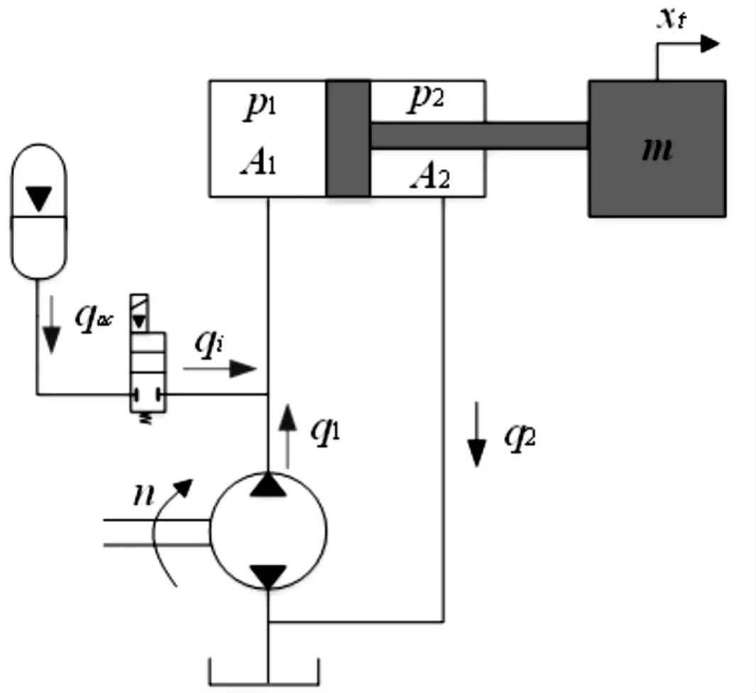
Fig.2 Hydraulic system working principle diagram of the EHA
2.2 Control scheme
The schematic of the position control of the proposed EHA is presented in Fig.3.As shown,the accumulator and motor-pump are two independent control circuits.The HAS_LSA PID controller is located in the main circuit,and its principle is to set the proportional gain to a large value,so that the motor and hydraulic pump run at high speed,at which the hydraulic cylinder piston is extended rapidly.When the difference between the actual and set displacements reaches the required range of positioning accuracy,that is,less than the switching threshold,the input of the PID controller is switched to a constant,which is smaller than the positioning accuracy,and the motor speed is reduced until it stops.This control method can effectively reduce the effect of the small error amplification on the system performance.In the start-up phase of EHA under no-load condition,the accumulator is the main power source.When the piston rod is fully extended,the EHA can withstand a certain external load under the operation of the pump.Therefore,the choice of accumulator is critical to ensure that the system starts in a stable manner.When the capacity of the accumulator is extremely large,the volume increases accordingly.When the outlet pressure of the accumulator is extremely high,the impact of the EHA during start-up stage is serious.In practical applications,neither the volume nor the impact is extremely large(not conducive to integration and smooth operation,respectively),the parameter design of the accumulator is discussed in detail in section 2.3.

Fig.3 Schematic of the position control of the EHA
2.3 Parameters of accumulator
The accumulator plays an important role in normal operation and improves the performance of the hydraulic system[24-25].A bladder type accumulator is used in this study.The bladder accumulator consists of a bladder,an inflation valve,a pressure-resistant casing,a mushroom valve,an orifice,a venting plug,and an oil passage connector.It has the advantages of small inertia,rapid responsiveness,separation of oil and gas,and easy installation[26].
Assuming that the stroke of the piston rod is xt,when the external load force is FL,the inner diameter of the cylinder is D,and the diameter of the piston rod is d.The required oil volume for this movement is given as follows:

In practice,there is loss at the orifice and during compression of the hydraulic oil under high pressure.Therefore,the effective oil volume of the accumulator is as follows:

Whereαis the coefficient andα≥1.This is because the volume of the accumulator should not be too large,assumingα=1.01.
The gas inside the bladder accumulator is generally inert,and its properties are close to the ideal gas,therefore the law of variation can be expressed as:

Where p0is the inflation pressure;V0is the gas volume;pa1and pa2are the minimum and maximum working pressures;Va1and Va2are the gas volumes at pressures pa1and pa2.n is the polytropic index,which is 1 for an isothermal process and 1.4 for an adiabatic process.The effective storage volume,ΔV,of the oil is equal to(Va1-Va2),so that,initial volume V0is as follows:

The accumulator is an auxiliary power source and releases pressure instantaneously after starting.Therefore,the process is assumed to be an isothermal process,with polytropic index n=1[27].The maximum working pressure of the accumulator directly determines the speed at which the piston rod extends.Within a reasonable range,larger pa2values lead to shorter piston rod extension times.
3 Mathematical model of PACM for an accumulator
The accumulator not only be functions as an auxiliary power source but also absorbs pressure and flow rate pulsation in the system to enhance the stability of the system.In[28],the accumulator was noted to have an optimal frequency for absorbing pulsation,and this frequency changed with the pressure pulsation in the system.To ensure adaptive adjustment of the accumulator frequency with pressure pulsation of the pump outlet,a variable gain controller was proposed in[28]for controlling the opening of the proportional valve at the outlet of the accumulator,however,the absorption effect of this method on the pulsation of pump outlet pressure is not very significant.
In this study,the accumulator was installed on the piston side of the hydraulic cylinder,and the flow area of the accumulator inlet was controlled by the electromagnetic proportional valve.In the start-up phase,the accumulator acted as an auxiliary power source.When the piston rod is extended to the specified displacement,it needs to push the load or maintain the original position during the sudden application of a load.When an external load is applied,the pressure pulsation and flow rate shock are observed in both chambers of the hydraulic cylinder,and these types of pulsation tend to have larger amplitudes,especially during heavy loads.Thus,a parameter adaptive controller for accumulator is designed,the block diagram of which is shown in Fig.4.Uvis the control signal applied to the proportional valve,Kuis the proportional constant,and xvis the displacement of the proportional valve spool.

Fig.4 Block diagram of PACM
In Fig.4,Sig(t)is the piecewise function on time,which is defined as follows:

Where t0is the time when the displacement of the piston rod reaches the specified position and t1is the loading time.The rod is expected to reach the specified position again after t2,andλ1,λ2are the adaptive coefficients of EHA under different working stage.
The derivation of the natural frequency of the accumulator-hydraulic cylinder circuit can be found in[28],in which the best frequency of the absorption pressure pulsation of the accumulator-hydraulic cylinder circuit is expressed as

Where ps0is the steady state pressure value of the accumulator-hydraulic cylinder circuit,K is the thermal insulation coefficient of the accumulator,Sais the flow area of the accumulator inlet pipe,l is the length of the accumulator inlet pipe,Vais the accumulator volume,andρis the density of hydraulic fluid.
When the pressure of the accumulator-hydraulic cylinder circuit fluctuates,assuming that the pulsatingpressure is p,the frequency of the accumulator can be given by

The accumulator can work at the optimal absorption frequency by adjusting the flow area Sa1 of the inlet pipeline.Assuming that Sa1=KaSa,let equations(6)and(7)be equal,we have

Therefore,the output of PACM is

In general,it is recommended to takeλ1=20 and 2≤λ2≤20.
4 Mathematical model
The proposed EHA system can be divided into two sub loops:a high pressure circuit with an accumulator and a high pressure outer circuit connected to the asymmetrical actuator.
4.1 Accumulator
According to the requirements of the system’s rapid start-up,a bladder type accumulator with a capacity of Vawas attached to the piston side to quickly extend the piston rod,allowing it to reach the given position at initial stage of working.The accumulator acts as an auxiliary power source,and its capacity is determined by the piston diameter of the actuator,the diameter of the piston rod,and the stroke of the piston rod.
If solenoid valve SOV1 is closed,the outlet flow rate of accumulator can be expressed as qi=0 and when SOV1 is open,qi=kSOV1Pac[13].Assuming that the process is an isothermal expansion and compression when the accumulator is released,output pressure Pacand the charge or discharge flow rate of accumulator can be expressed as:

Where p0is the initial inflation pressure of the accumulator,V0is the initial volume of the accumulator,and kSOV1is the valve coefficient.
Therefore,the flow rate into the rodless cavity of the hydraulic cylinder is expressed as

4.2 Electric motor
A high performance servo motor was used to drive the hydraulic pump.An expression for the angular speed of the motor is given by Ren et al.[29]as shown in equation(13)

Whereωmis the angular speed of motor,u represents the input voltage to the servomotor,and Kemandτmare the servomotor gain and time constant,respectively.
We can derive the derivative of speed nmof the motor as

Where Ktm=Kem/2π.
By applying Laplace transformation to equation(9),the following transfer function,which relates motor speed Nm(s)to the input voltage U(s),could be obtained:

Where Kmis the gain coefficient of the transfer function.
4.3 Hydraulic pump
A bi-directional gear pump was used to convert mechanical energy of the motor to hydraulic energy.The gear pump has three ports,namely the inlet,the outlet,and drain ports.In the studied system,the drain port was connected to the tank.The accuracy of the EHA control was directly determined by the volumetric displacement of the gear pump.The smaller the volume displacement of the pump,the higher is the resolution and the lower is the rotational speed.However,as the speed of the piston rod is proportional to the volume displacement,the larger the volume displacement,the higher is the speed and the is lower the accuracy.Therefore,the maximum speed and position control resolution work in an opposing manner,and trade-off is made according to specific needs.
The flow continuity equation of the bidirectional gear pump can be represented as

Where DPis the pump displacement,nmis the motor speed,K1and K2are the leakage coefficients,ξis theleakage coefficient of the pump cross port,ppipeis the pressure of pipeline,and paand pbare the gear pump’s inlet and outlet pressure,respectively,when the gear pump is directly connected to the hydraulic cylinder;pa=p1and pb=p2.Therefore,the load flow rate of the gear pump can be represented as

4.4 Single-rod hydraulic cylinder
Fig.4 shows the relationship between the flow rate and pressure of the hydraulic cylinder.In this study,the internal leakage of the high/low pressure chamber in the hydraulic cylinder was considered in the modeling.Considering compressibility of hydraulic oil and transient fluid flow dynamics,the flow continuity equation of the hydraulic cylinder are given by[23]

Where A1is the effective area at the piston-side,A2is the effective area of the rod chamber piston,βeis the effective volume elastic modulus of the hydraulic oil,Cipis the internal leakage coefficient of the hydraulic cylinder,V10and V20are the initial volumes of the two chambers of the hydraulic cylinder,and Vpipeis the volume of each of the two connecting pipes.
In addition,the dynamic equation of the cylinder is expressed as

Where xtis the piston displacement,Mtis the mass of load and piston converted to the piston rod,FLis the external load force,and b and k are the effective viscous damping coefficients of the actuator and load stiffness,respectively.
4.5 Overall system model
When the accumulator and pump work simultaneously,the flow continuity equation of the EHA can be described by

By substituting equations(12)and(18)into equation(22),the piston rod speed can be expressed as

According to equation(23),the rate of change of the piston rod speed is positively proportional to the pressure difference between the two sides of the piston.In addition,the accumulator instantaneously releases the high pressure much faster than the motordriven hydraulic pump builds pressure.In addition,the main factors that affect the rapid start of the EHA are external load,viscous friction,and fluid stiffness.
5 Simulation results and discussion
The main parameters of the simulation model are shown in Table 1,and the simulation model of the EHA is shown in Fig.5.
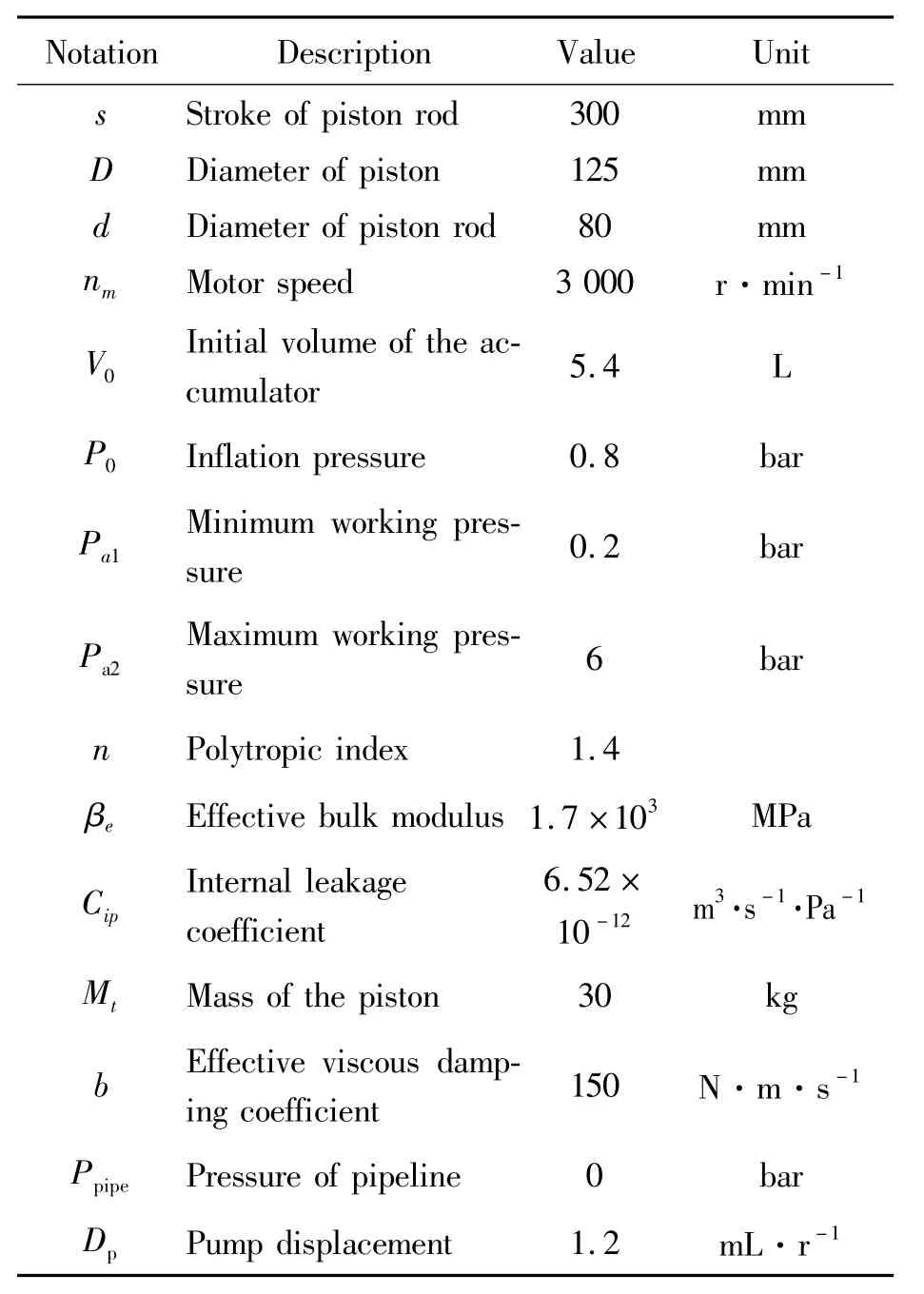
Table 1 Simulation parameters of the EHA model

Fig.5 Simulation model of the EHA
5.1 Star-tup characteristics of EHAwith HAS_LSAPID
The HAS_LSA PID algorithm was used for position control.In the start-up stage of EHA,we set Kpat a high gain.When the actual displacement increases to 95%of the set value,Kpis decreased to a low gain.Although the HAS_LSA PID algorithm is helpful for reducing the start-up time,it can prevent small errors from being excessively amplified at high gains that causes the piston rod to overshoot.Its parameters were set as Kp=20 000,Ki=0.01,and Kd=0 before switch threshold.When switch threshold is set at St=xts×0.95 m,t Kp=5 000 in the low speed adjustment stage.Different external loads were applied at 70 s.The piston rod displacement of EHA and pressure and flow rate in high pressure chamber of hydraulic cylinder are shown in Fig.6 and Fig.7,respectively.As shown in Fig.6,the start-up time for the piston rod to reach the given position of 0.3 m is 62.8 s.As the external load increases,the displacement at the moment of loading fluctuates severely.
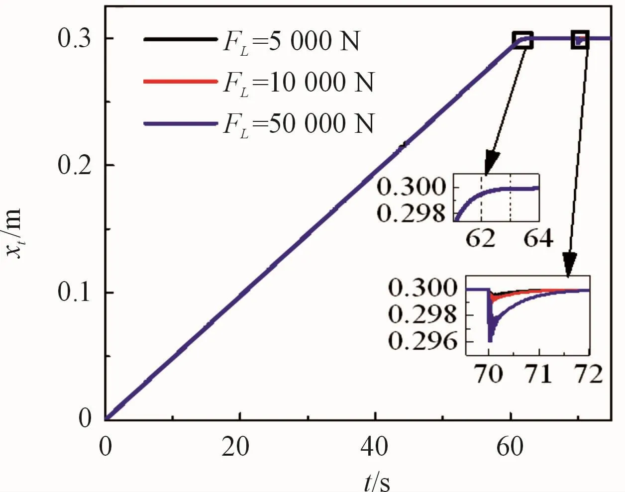
Fig.6 Displacement response of the EHA with HAS_LSA PlD.
According to Fig.7,the pressure and flow pulsation in the high pressure chamber of the hydraulic cylinder increase with the external load.The larger the external load,the greater are the fluctuation of pressure and flow at the moment of loading.In practical applications,the pressure pulsation and flow shock are not conducive to the smooth operation of the EHA system.
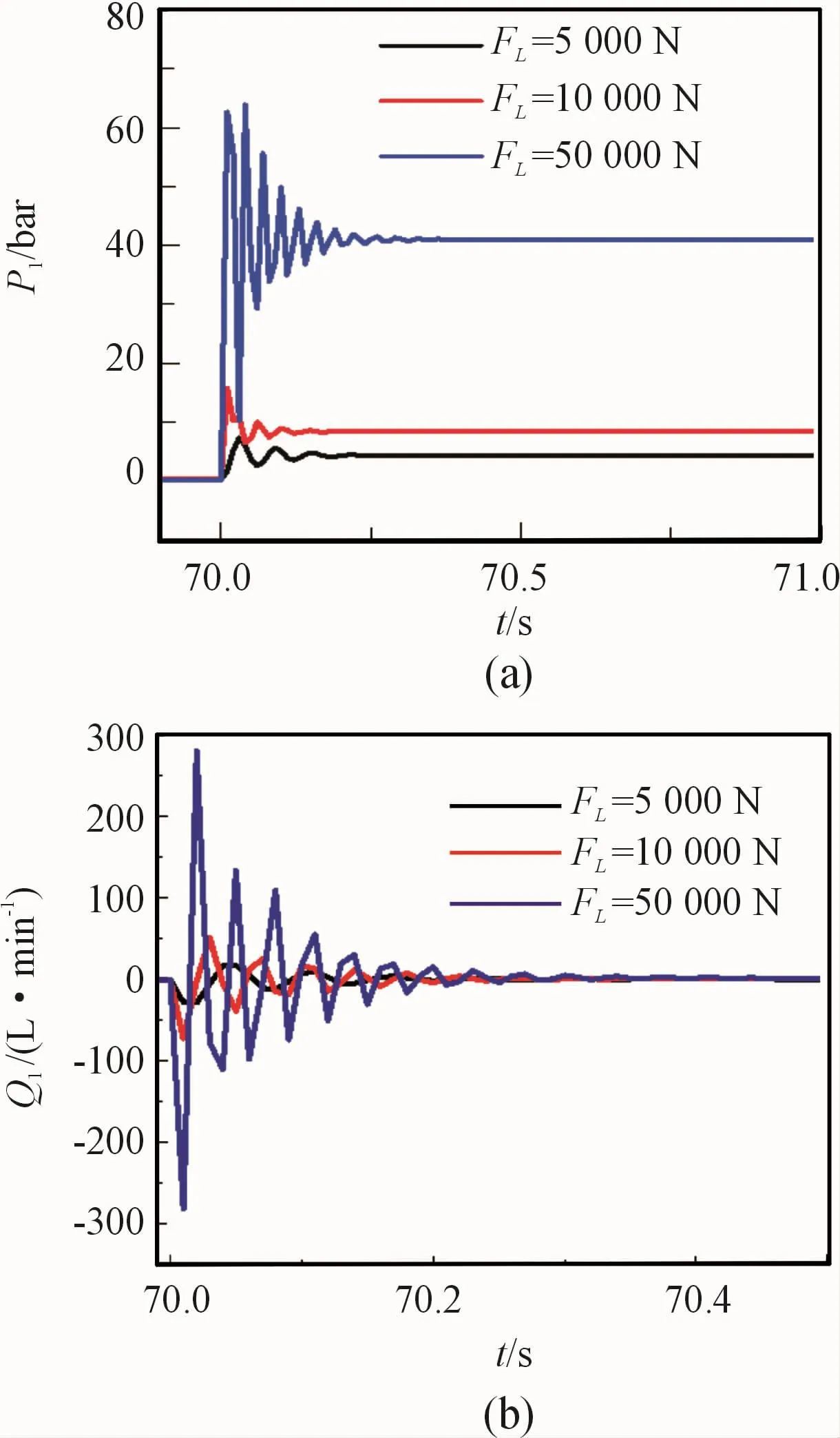
Fig.7 Pressure and flow rate changes of EHA with HAS_LSA PlD under different loads.(a)Pressure and(b)flow rate at the piston-side of the hydraulic cylinder
5.2 Start-up characteristics of EHAwith HAS_LSAPID and accumulator
The parameters of HAS_LSA PID are the same asthose in section 5.1,λ1andλ2of PASM are set to 10 and 2,respectively.
The parametric comparison of the EHA system based on the proposed and the HAS_LSD PID control methods are shown in Fig.8,Fig.9 and Fig.10.As shown in Fig.8(a),the time required for the EHA with the accumulator to rapidly extend to the given position is 2.1 s.This implies that compared with the start-up time of EHA with only the HAS_LSA PID algorithm,that of the proposed EHA is shortened by 96.6%.When an external load of 5 000 N is applied at 70 s,the displacement retention capacity of EHA without an accumulator is better than with the accumulator;however,the fluctuations of speed,pressure,and flow rate caused by the load are large.After adding the accumulator with PACM,the pressure pulsation was reduced by approximately 31%,and the flow rate curve was excessively smoother.Further,the absorption of pressure pulsation and reduction of flow shock are mutually balanced with the ability to maintain a position.As shown in Fig.9,the accumulator pressure decreases from6 to 0.3 bar during the 2.1 s,and a large flow rate is released,when an external load is applied at 70 s.The flow rate pulsation absorbed by the accumulator is shown in Fig.9(b),where the pressure increased slightly.As shown in Fig.10,after the accumulator is added,the pump outlet pressure and flow rate are greater,and the flow rate is increased by approximately 2.4 times;that is due to the poor retention capacity of the displacement of EHA with accumulator as it is slightly weaker under external loads.
Based on the above-mentioned analysis,the addition of an accumulator can not only achieve the purpose of rapid start-up but also absorb the pressure and flow rate pulsation on the high pressure oil line of the EHA system.The performance of the proposed adaptive parameter controller of the accumulator is also good.
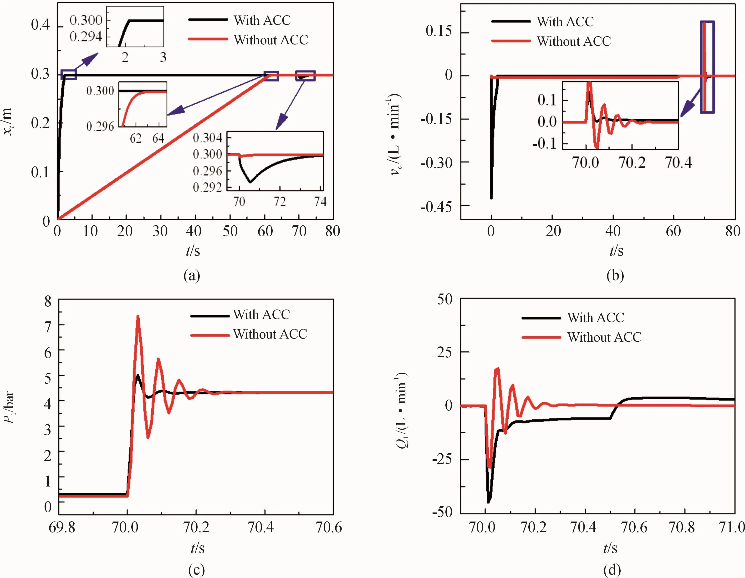
Fig.8 Variations in parameters of the EHA with and without accumulator(ACC).(a)Displacement of piston;(b)speed of piston;(c)pressure and(d)flow rate at the piston-side of the hydraulic cylinder
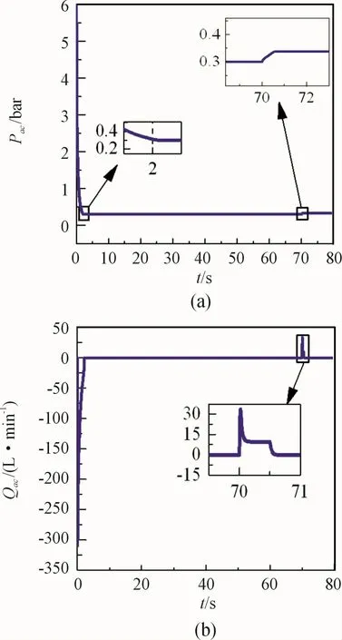
Fig.9 Parameters of accumulator:(a)pressure and(b)flow rate at the outlet

Fig.10 Parameters of the pump:(a)pressure and(b)flow rate at the outlet
5.3 Pulsation absorption performance of the accumulator using the PACM under different heavy loads
For the external loads of 10 000 N and 50 000 N,the absorption effect of the pressure and flow rate pulsation in the high pressure chamber of the hydraulic cylinder were analyzed,and the corresponding results are shown in Fig.11 and Fig.12.It can be seen from Fig.11 that the accumulator has a significant effect on absorbing pressure pulsation in the high pressure chamber of the hydraulic cylinder under heavy load.Especially,when the external load is 50 000 N,the pressure pulsation are reduced by approximately 30%.According to Fig.12,the flow shock of EHA with an accumulator is greater when the load is suddenly applied but become gentler.
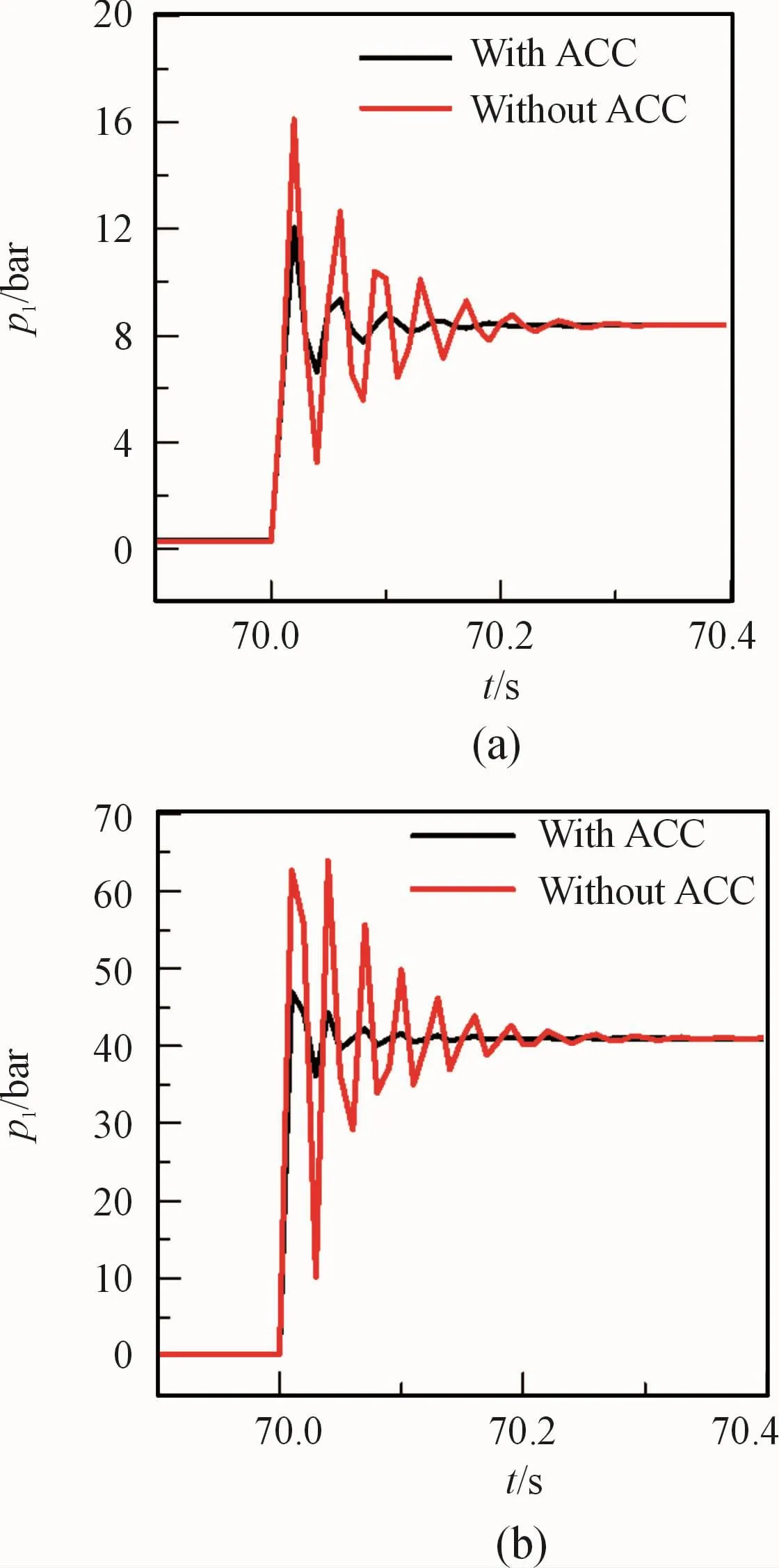
Fig.11 Pressures at the piston-side of the hydraulic cylinder.(a)FL=10 000 N and(b)FL=50 000 N
As mentioned earlier,there must be a trade-off between the absorption effect of the accumulator on the pressure and flow pulsation and the position retention capability.Fig.13 shows the displacement changes of the EHA with and without the accumulator under different large loads.Fig.13 and Fig.14 show that the larger the external load,the worse is the displacementretention capacity,the better is the pulsation absorption effect,and the greater is the impact on the flow rate of the accumulator.

Fig.12 Flow rate at the piston-side of the hydraulic cylinder for(a)FL=10 000 N and(b)FL=50 000 N
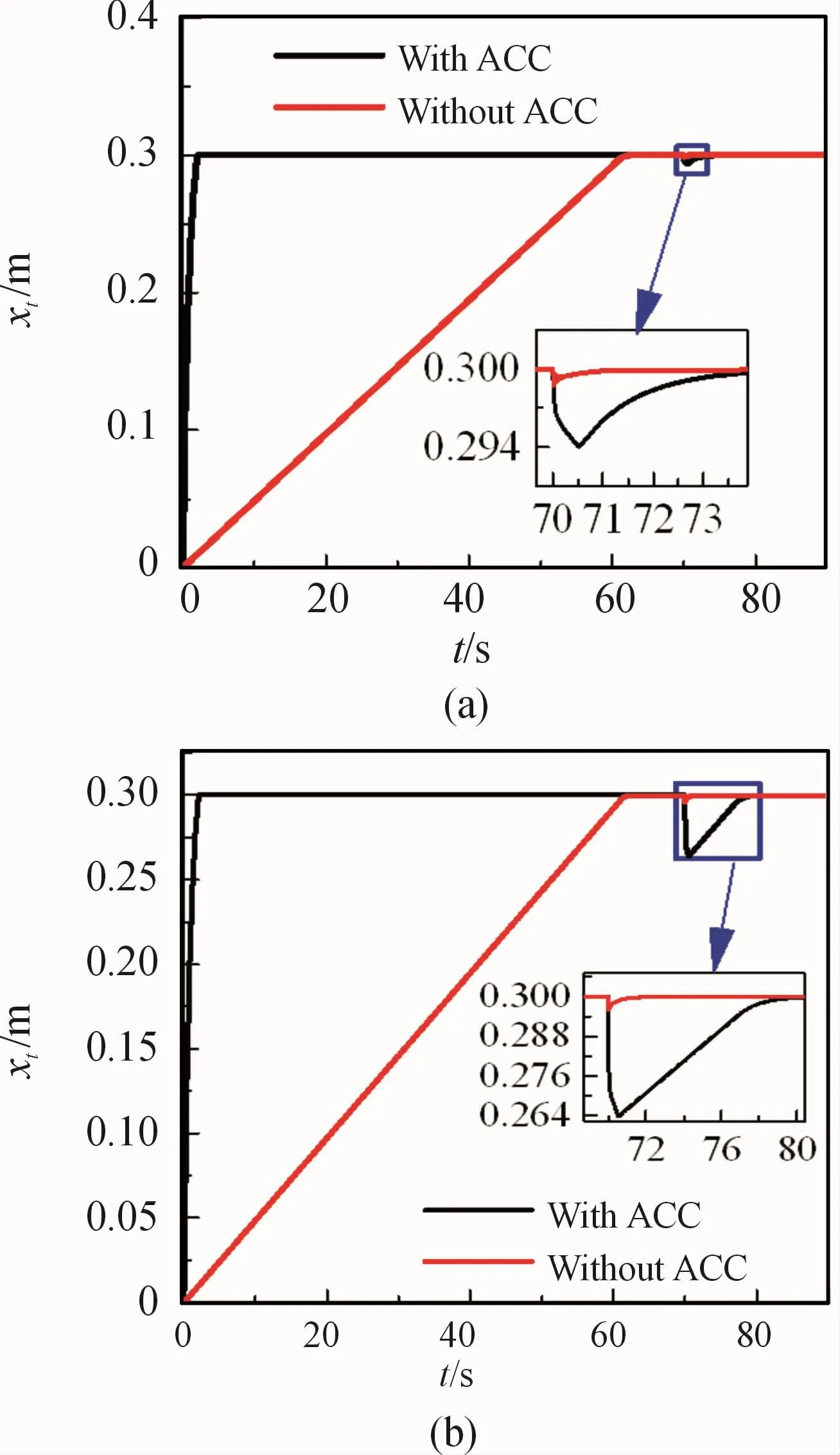
Fig.13 Piston displacement of the hydraulic cylinder at(a)FL=10 000 N and(b)FL=50 000 N
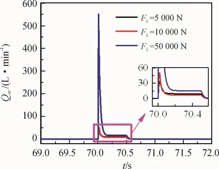
Fig.14 Outlet flow rate of accumulator under different FL
5.4 Pulsation absorption performance of accumulator under different parameters of PACM
Next,we compared the changes in p1,Q1,and xtwhenλ2=2,8,12,and 20 and the external load was 50 000 N;the results are shown in Fig.15 and Fig.16.
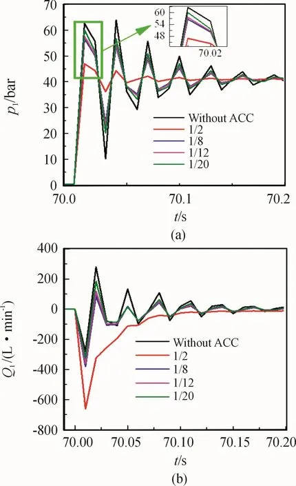
Fig.15(a)Pressures and(b)flow rate at the piston-side of the hydraulic cylinder under different values ofλ2
As shown in Fig.15,the accumulator’s absorption effect on the pressure and flow rate pulsation in the high pressure chamber of the hydraulic cylinder decreases asλ2increases;however,the absorption canstill be adapted according to the actual pulsation of the pressure and flow rate.As shown in Fig.16,the position-retention capability of the piston rod increases asλ2increases.Based on the above-mentioned analysis,in the case where high positioning accuracy is required,a large value ofλ2must be utilized.
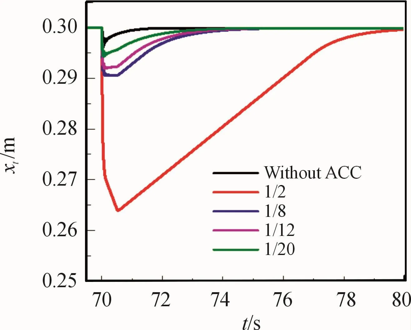
Fig.16 Piston displacements of the hydraulic cylinder under differentλ2 values
6 Conclusions and perspectives
In the present paper,a new structure that involves the attachment of an accumulator on the line at the piston side of the hydraulic cylinder was proposed to achieve the purpose of rapid start-up of EHA.In addition,the conventional PID controller was improved to HAS_LSA PID controller to compare with the proposed method.Moreover,a new PACM was proposed for accumulator to optimally absorb the pressure and flow rate pulsation of the system.The simulation results demonstrate that the proposed new structure can shorter start-up time under no-load,and the start-up time of EHA with accumulator is 2.1 s.Compared with the conventional structure,the start-up time of EHA is shortened by approximately 96.6%.The pressure and flow rate pulsation can be absorbed well by the accumulator using the PACM when an external load is applied,and the PACM for the accumulator showed better performance and required simple parameter adjustment.However,the pulsation absorption effect of the accumulator and the position retention capability of EHA are a compromise.Our study provides significant guidance for EHA start-up characteristics.In the future,an experimental research can be conducted on the proposed scheme,and the heat problem where the accumulator rapidly releases the flow rate can be considered.
- 机床与液压的其它文章
- Lubricating performance of conical spindle distribution in the ball piston pump
- Mechanism analysis and control of asymmetrical digital cylinder
- Reliability analysis and calculationof the drive hydraulic system group of combined transportation
- Reliability analysis for cutterhead hydraulic drive system of remanufactured shield machine
- Application of compound buffer hydraulic cylinder in electro-hydraulic load simulator(EHLS)
- Research on dynamic characteristics of vehicle shifting buffer valve

