Application of compound buffer hydraulic cylinder in electro-hydraulic load simulator(EHLS)
Xiao-lin LIU,Qiu-min HAN,Zhuo LI
(1Key Laboratory for Advanced Signal Processing,Civil Aviation University of China,Tianjin 300300,China)
(2College of Information and Electrical Engineering,China Agricultural University,Beijing 100083,China)
Abstract:In order to solve the problem of the forced flow in two cavities of the hydraulic cylinder caused by the active motion of the rudder in different gradient loading experiments of aircraft rudder electro-hydraulic load simulator(EHLS),and then leads to surplus torque interference,thus the system structure design based on compound buffer hydraulic cylinder is proposed.For the working principle of the system and the characteristics of hydraulic buffer structure,the structure form of the hydraulic cylinder is designed and the mathematical model is established.The simulation model of the actuator is established through the AMESim simulation software,and the dynamic characteristic experiments are carried out.The results show that the hydraulic cylinder system can not only reduce the mechanical collision during the operation of the piston,and alleviate the forced flow pressure,but also suppress and eliminate the interference of surplus torque.In addition,the load performance of EHLSis improved with high engineering practice value.
Key words:Electro-hydraulic load simulator,Compound buffer hydraulic cylinder,Surplus torque,Aircraft rudder,Load performance
1 Introduction
Aircraft rudder is an important part of the flight control system,and its function is to overcome the influence of complex air aerodynamic load and accurately transform the control command into the deflection angle of the rudder surface to control the pitch,tilt and course of the aircraft[1].Under laboratory conditions,the operation performance and working status of the rudder under different flight conditions are usually studied by the EHLS of aircraft rudder,and to simulate the change of aerodynamic hinge force on aircraft in real flight environment.This method has the advantages of simple structure,short development time,less research funds and so on.The EHLS generally uses the hydraulic cylinder as the power actuator,which generates the loading force under the control of the electro-hydraulic servo valve,and loads the simulated aerodynamic load on the rudder through the buffer spring.However,due to the hydraulic cylinder rapidly driving the rudder to reciprocate in a straight-line,the generation of large kinetic energy,so the load simulator caused pressure and blunt force impact is larger,and ultimately make the system work is not smooth,affecting the high-power hydraulic energy sig-nal transmission and mechanical energy signal conversion[2].In addition,due to the active motion of the aircraft rudder,the two cavities of the hydraulic cylinder connected to it in a straight line caused by force flow,which leads to the interference of surplus torque,reducing the loading accuracy and dynamic characteristics of the experimental equipment[3-4].
In view of this,the paper uses the compound buffer hydraulic cylinder to replace the common hydraulic cylinder to optimize the structure of the EHLS,uses AMESim software to build the simulation model,and verifies the feasibility and effectiveness of the structural improvement through simulation experiments.
2 Working principle of EHLS
The EHLS is a typical position servo control system,which is composed of industrial control computer,electro-hydraulic servo valve,compound buffer hydraulic cylinder,rubber metal buffer spring,force sensor,position sensor,and aircraft rudder[5].Its working principle is shown in the Fig.1.Firstly,the industrial control computer sets the loading gradient and multiplies it with the position signal detected by the position sensor to obtain the loading instruction signal.The force sensor is used to obtain the actual loading force signal to form a closed-loop feedback control,and the adjustment error is obtained by comparing with the force command signal.Then,the adjustment error is D/A converted to obtain a digital control signal,which is amplified by the signal conditioning circuit and through the electro-hydraulic servo valve to become a high-power hydraulic energy signal,to drive the compound buffer hydraulic cylinder to act.Finally,the compound buffer hydraulic cylinder outputs the mechanical energy signal,which is transmitted by the rubber metal buffer spring to load the force signal under different loading gradients on the rudder.

Fig.1 Principle diagram of EHLS
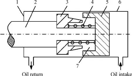
The characteristics and innovations of this system are the design of a new compound buffer hydraulic cylinder to replace the common hydraulic cylinder,the design of a structure with a built-in buffer device in the cylinder to replace the outer buffer structure of the complex hydraulic cylinder piston,then integrate the principle of mechanical buffer and hydraulic buffer to achieve the purpose of buffering.The buffer device is built in the hydraulic cylinder to achieve the purpose of buffer.The compound buffer hydraulic cylinder is composed of an end cover,a piston rod,a buffer piston,a spring,a piston and a cylinder barrel,etc.Its structural diagram is shown in the Fig.2.Among them,the piston rod is rigidly connected with the buffer piston,and the buffer piston is flexibly connected with the piston,and they together with the spring constitute the buffer device in the cylinder,which has the advantages of simple structure,small size,high-pressure shock resistance,short braking distance and so on.During the working process of the hydraulic cylinder,the control command of the electro-hydraulic servo valve is received to drive the piston rod to act,and then the piston rod moves forward to the end of the stroke until the buffer piston contacts the end cover.At this time,the buffer piston enters the cavity of the end cover of the hydraulic cylinder under the action of the spring to start the buffer process.When the buffer piston continues to run until it comes to contact with the piston,the hydraulic oil sealed between the piston rod and the cylinder flows out from the gap between the flange of the buffer piston and the inner wall of the piston due to the contract between the two ends,forming a throttling effect,this causes the pressure of the oil in the buffer cavity torise sharply,and provides the reverse braking force to the piston,thereby achieving the purpose of deceleration and alleviating flow pressure[6].The spring ensures that the buffer piston is separated from the piston when the hydraulic cylinder is working,and plays an auxiliary buffering role.In the process of variable gradient loading experiment,the compound buffer hydraulic cylinder can not only avoid the mechanical collision caused by the sudden stop of the valve port and the continuous motion of the flowing liquid and moving parts due to the inertia force,but also buffer the pressure difference between the two cavities of the hydraulic cylinder due to the forced flow,effectively restrain the interference of the residual force,so as to improve the overall loading performance of the EHLS.

Fig.2 Structure diagram of compound buffer hydraulic cylinder
3 Structural optimization design of compound buffer hydraulic cylinder
3.1 Structure of compound buffer hydraulic cylinder
According to the loading requirements of the aircraft rudder and the testing needs of the EHLS,under the actual constraints of the aircraft rudder’s maximum movement displacement and speed,which are 120 mm and 150 mm/s,and it’s movement frequency of 1~10 Hz,in order to achieve high-speed hydraulic cylinder buffer braking while reducing the surplus torque,the structural parameters of the system under static and dynamic working conditions are:The rated working pressure is 28 MPa;the maximum load force on the piston is 3×10⁵N.According to the above-mentioned structural parameters,determine the external dimensions of the compound buffer hydraulic cylinder and the diameter of the piston rod in the cylinder.
In this system,a single piston rod hydraulic cylinder is used to complete the power output to drive the operation of the aircraft rudder of the working mechanism[7].First of all,calculate the inner diameter of the hydraulic cylinder and the diameter of the piston rod.

Where D is the inner diameter of the hydraulic cylinder,F is the load on the piston,P is the working pressure of the system,d is the diameter of the piston rod,φis the ratio of the retraction velocity to the protruding speed of the piston in linear reciprocating motion.
Considering the sealing size of the hydraulic cylinder,the inner diameter of the designed hydraulic cylinder is 160 mm and the diameter of the piston rod is 80 mm.The piston area of the hydraulic cylinder is calculated to be:

Finally,the wall thickness of hydraulic cylinder is calculated.Due to the small size of the hydraulic cylinder used,it can be approximated as a thin-walled cylinder,which can be obtained according to the formula for calculating the wall thickness of the thinwalled cylinder in material mechanics:

In equation(4),δis the wall thickness of the cylinder,[σ]is the allowable stress is the thickness of the cylinder.It can be obtained that the cylinder wall thickness of the hydraulic cylinder selected in this paper is 22.5 mm.
3.2 Mathematical model of compound buffer hydraulic cylinder
Compound buffer hydraulic cylinder is the core part of the EHLS,and its technical specifications directly affect the overall performance of the system.Taking the output pressure,output flow,and piston rod speed change of the hydraulic cylinder under step input as indicators,in order to compare and verify the improvement of the cushioning performance and control performance of the composite cushioning hydraulic cylinder,the mathematical model of the internal structure of the cylinder is established.The friction resistance of the seal is much smaller than the inertia force,therefore the friction coefficient between the hydraulic cylinder and the piston rod and the viscosity damping coefficient of the hydraulic oil can be ignored[8-9].The load balance equation and the flow continuity e-quation of the hydraulic cylinder are established as:

Which

According to the size and shape of the throttle hole of the buffer piston,the flow expression of the hydraulic cylinder is established:

Where m is the equivalent total mass of the piston and the load,A2is the piston displacement,P2is the pressure of the high pressure cavity of the hydraulic cylinder,A2is the effective area of the piston of the high pressure cavity of the hydraulic cylinder,P1is the pressure of the low pressure cavity of the hydraulic cylinder,A1is the effective area of the piston of the low pressure cavity of the hydraulic cylinder,Bpis the viscous damping coefficient of the piston,q is the output load flow,Vtis the effective volume of the buffer cavity of the hydraulic cylinder,Eyis the equivalent volumetric modulus of elasticity,Cslis the total leakage coefficient of the hydraulic cylinder,Pfis the load pressure drop at both ends of the hydraulic cylinder,Ffis the friction resistance caused by mechanical friction,ΔQis the pressure loss of the piston throttle hole,k is the elastic coefficient of the buffer spring of the buffer device,K1is the flow coefficient of the hydraulic cylinder,A is the effective area of the throttle orifice,Δp is the pressure difference between the two cavities of the hydraulic cylinder.
4 Simulation experiment and analysis of EHLS
In order to verify that the compound buffer hydraulic cylinder can reduce the forced flow of the system,eliminate the impact in the process of cylinder block transmission and restrain the interference of surplus torque.In this paper,AMESim simulation software is used to build the simulation model of the compound buffer hydraulic cylinder and then the simulation model is applied to the simulation experiment of the EHLS.
4.1 Simulation model of compound buffer hydraulic cylinder
AMESim is an object-oriented simulation software that integrates system modeling,parameter debugging,simulation experiment and result analysis.Its working process is as follows:first,master the working principle of the system and determine the model parameters of each system component,then connect the component submodels of the component library to build the simulation model of the whole system,and finally select the operation mode of simulation experiment,and make the experimental analysis through the experimental results.AMESim’s platform is built and simulated in the way of graphical interface,which is free from complicated language programming environment,and is suitable for many fields such as mechanical design,system control,hydraulic transmission and so on[10-12].Therefore,AMESim software is selected to build the simulation model of compound buffer hydraulic cylinder.According to the above working principle and structure design,each component module of the structure diagram shown in Fig.3 is determined,and the structure parameters and simulation parameters of the components are set.The AMESim model of compound buffer hydraulic cylinder is shown in Fig.3.

Fig.3 AMESim simulation model of compound buffer hydraulic cylinder
In order to test the buffering performance of the hydraulic cylinder,in the process of AMESim model simulation,the actual position and velocity signals of the piston of the hydraulic cylinder and the flow and pressure signals of the two cavities of the hydraulic cylinder are obtained by using a high-precision sensor and a high-precision data amplifier to form a closedloop control.At the same time,the mathematical model of the compound buffer hydraulic cylinder and the corresponding control link are added in.
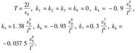
The parameters of the AMESim simulation model of the compound buffering hydraulic cylinder are set as follows:piston initial speed v0=0.4 m/s,rated pres-sure Ps=28 MPa,stroke l=320 mm.Assuming that there is no sudden change in the acceleration of the piston running to the end of the stroke under the ideal condition,that is,there is no soft impact effect,the functional expression of the piston stroke and buffer time is:

According to the working principle of the compound buffer hydraulic cylinder,the constraint conditions of the buffer process can be obtained as follows:
When t=0,x=0,v=v0,a=0,J=0;whenwhen t=T,x=l,v=0,a=0,J=0.
where v is the instantaneous speed of the piston running at any time,a is the acceleration of the piston movement,J is the deceleration change rate of the hydraulic cylinder in the buffering process.

By solving it,the following data could be obtained:

4.2 Simulation experiment of EHLS
According to the working state of the compound buffer hydraulic cylinder in the EHLS,the AMESim simulation model is established,and the system loading instruction is set as a step signal.The buffering effect of the optimized structure and the ordinary hydraulic cylinder on the forced flow of the cylinder block and the restraining effect on the surplus torque on the system are compared and analyzed.
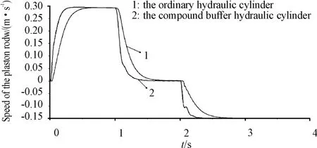
When the system loading instruction is a step signal,the comparison curves of the output pressure,output flow rate and speed of the piston rod of the hydraulic cylinder are obtained as shown in the Figs.4,5,6.
According to Fig.4,it can be seen that when a step-like loading instruction is applied to the system,the output pressure curve of the ordinary hydraulic cylinder is relatively smooth,and the maximum amplitude can reach 130 bar.While the output pressure curve of the compound buffer hydraulic cylinder appears more jitter,showing obvious non-linear characteristics,the amplitude changes with the loading instruction,the buffering effect is significant,and can effectively reduce the output pressure and thus reduce the surplus torque of the system.

Fig.4 Output pressure contrast curve of hydraulic cylinder

Fig.5 Output flow contrast curve of hydraulic cylinder
According to Fig.5,it can be seen that the change trend of the output flow curve of the two different actuators is roughly the same,showing a good quality of the transition process,but the rising time of the step response curve of the compound buffer hydraulic cylinder is short and the response speed is fast,and the amplitude of the final output flow is smaller than that of the ordinary hydraulic cylinder.It shows that the compound buffer hydraulic cylinder has an obvious restraining effect on the surplus torque compared with the ordinary hydraulic cylinder.

Fig.6 Speed contrast curve for piston rod of hydraulic cylinder
According to Fig.6,it can be seen that during the action of the piston of the compound buffer hydraulic cylinder,the dynamic response characteristic of the piston rod is good,and the response speed is obviously better than that of the ordinary hydraulic cylinder,and when the piston runs to the end of the stroke,its speed decreases rapidly.The results show that when the input instruction is a step signal,the output pressure and flow of the compound buffer hydraulic cylinder adopted in this paper are small,and the response speed is fast,which can effectively reduce the forced flow of the two cavities of the hydraulic cylinder,and then effectively buffer the movement speed of the piston.to a certain extent,the influence of hard impact is restrained.
5 Conclusions
In view of the fact that the dynamic performance of the compound buffer hydraulic cylinder not only affects the power transmission performance of the aircraft rudder EHLS,but also determines the control quality of the simulation technology.Therefore,an aircraft rudder EHLSwith compound buffer hydraulic cylinder structure is designed.According to the working principle of the system and the characteristics of the hydraulic buffer structure,the structural parameters of the system are set,the structural size of the compound buffer hydraulic cylinder is calculated,and the mathematical model of the optimized structure is established.At the same time,in order to verify the effectiveness and rationality of the system design,the simulation experiment of EHLS is carried out by using AMESim simulation software.The main conclusions are as follows:
1)Compared with the common hydraulic cylinder,the compound buffer hydraulic cylinder can eliminate the hard shock and reduce the soft shock generated during the operation of the piston,relieve the forced flow of the two cavities of the hydraulic cylinder and restrain the surplus torque interference.
2)The hydraulic cylinder has good dynamic response characteristics,little interference from the load,and obvious buffering effect.To sum up,the compound cushioning hydraulic cylinder used in this system has high engineering practical value for the structural optimization design of the EHLS.
- 机床与液压的其它文章
- Lubricating performance of conical spindle distribution in the ball piston pump
- Mechanism analysis and control of asymmetrical digital cylinder
- Reliability analysis and calculationof the drive hydraulic system group of combined transportation
- Reliability analysis for cutterhead hydraulic drive system of remanufactured shield machine
- Start-up characteristics of a new electro hydrostatic actuator with an accumulator
- Research on dynamic characteristics of vehicle shifting buffer valve

