Lubricating performance of conical spindle distribution in the ball piston pump
Jun-jie ZHOU,Chong-bo JING,Miao-miao WANG,Jian-hao LIU
(1School of Mechanical Engineering,Beijing Institute of Technology,Beijing 100081,China)
(2 Advanced Technology Research Institute(Jinan)of Beijing Institute of Technology,Jinan 250000,Chian)
Abstract:Conical spindle distribution is a new structural design for flow distributing used in hydraulic machines that combined the advantages of both cylindrical spindle distribution and plane flow distribution.In this paper,the steady condition of conical spindle distribution and its dynamic response under the changing load will be investigated.The lubrication model in spherical coordinate system is developed based on the particular structure.From force analysis,the dynamic model of conical spindle distribution in axial and radial freedoms is also constructed.The static and dynamic lubricating performance including the shaft eccentricity and distribution gap height is obtained by solving the model with a numerical method.The result shows that the shaft eccentricity and distribution gap height oscillate intensely under the impact load and gets back to a balance position in a short time.Such a self-adaptive feature of the lubrication performance of conical spindle distribution without requiring external adjustment is significant to ensure the reliability as the ball piston pumps working.
Key words:Ball piston pump,Lubricating performance,Conical spindle distribution
1 Introduction
As a new type of radial hydraulic pump,ball piston pump relies on the eccentricity of the cylinder and the outer ring to drive the ball piston reciprocating in the cylinder hole,including the suction stroke and delivery stroke.Its structure is shown in Fig.1.Compared with the traditional axial piston pump,ball piston pump has the advantages of small axial size,high power density,simple structure,etc.,so it has a wide prospect of application[1].
In order to reduce the leakage of the ball piston pump,a new method of flow distributing named conical spindle distribution that combined the advantages of both cylindrical spindle distribution and plane flow distribution is used.There are balance grooves in conical spindle to eliminate the radial force,as shown in Fig.2.

Fig.1 Structure of the ball piston pump
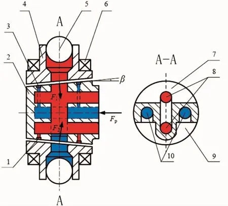
Fig.2 Schematic of the conical spindle distribution
F.M.Stansfield is one of the earliest scholars to study the conical sliding bearing.He has analyzed the one-dimensional flow of single-cavity and multi-cavity conical hydrostatic bearings by analytic method.Through calculating he got the approximate result of performance such as effective area,load capacity,stiffness,flow,resistance and power consumption[3].
P.J.Prabhu has analyzed the performance of the annular cavity conical sliding bearing with capillary and the throttle.In the one-dimensional flow state,he used the analytic method to derive the pressure distribution expression,and obtain the analytical results of static load capacity,static stiffness,flow,frictional power consumption on the sealing surface,dynamic stiffness,damping,etc.[4-5].

Fig.3 Structure of conic thrust bearings
A.EL.Kagar has studied on non-Newtonian fluid working condition of conical hydrostatic bearings which has static pressure chamber on edge of spindle and continuous oil film on conical surface.He has analyzed the influence of the conical angle,the rotational speed,the radius ratio of the oil cavity and the oil pressure on the bearing performance and designed the experiment for verifying the theory[6].
However,there is little research on parameter optimization of conical sliding bearings.S.Yoshimoto has used a linear method to optimize the design of the gas tapered bearings with the aim of finding the best taper angle for best bearing stability[7].
2 Lubrication model
The difference between conical and cylindrical spindle flow distribution spindle is the presence of a taper angle so that conical flow distribution has the advantage of self-compensation for gap.Considering the structure of conical spindle flow distribution,build the spherical coordinate system with the conical vertex as the origin,circle angleθ,half cone angleβ,pole diameter r as the axis shown in Fig.4.Based on the condition that oil is full of the gap between spindle and cylinder,combining the fluid continuity equation and N-Sequation in this coordinate we can obtain the lubrication equation:


Fig.4 Spherical coordinate system of the distribution pair
The change of the distribution spindle’s position will affect the film thickness from the axial and radial aspects because the spindle has a linear motion freedom in both radial and axial directions.The equation of the film thickness perpendicular to the direction of the cone is:

Radial movement of the spindle makesεchange and axial movement makes h0change so that the film thickness can be affect by movement in the two direc-tions.
To solve the Reynolds equation,the boundary condition is studied from a hydraulic resistance network.As is shown in Fig.5,the oil with high pressure flows from outlet to low pressure damping groove through gap and the pressure is reduced to p1.Then some flows to the edge and the other flows to inlet through damping hole with pressure being reduced to p0and pl.We define this flow field as I field.Oil also flows through high pressure damping groove and the pressure is reduced to p2.Some the oil flows to the edge and the other flows to inlet.We define this flow field as II field.Some the oil in high pressure groove will flow to low pressure groove along the circumference so that the two flow fields are linked,as shown in Fig.6.
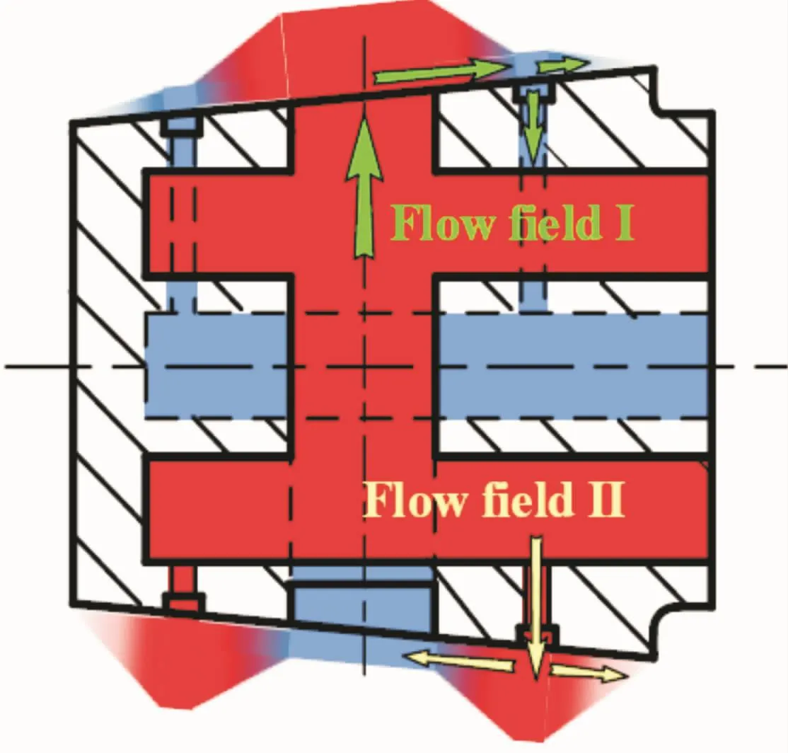
Fig.5 Flow field in distribution shaft

Fig.6 Equivalent hydraulic resistance network
Based on the hydraulic resistance network method,the following equations can be obtained from the flow balance of I and II flow field:

So we can get the pressure of high and low damping groove and then the lubrication model can be solved by using the finite difference method and pressure distribution is also described.
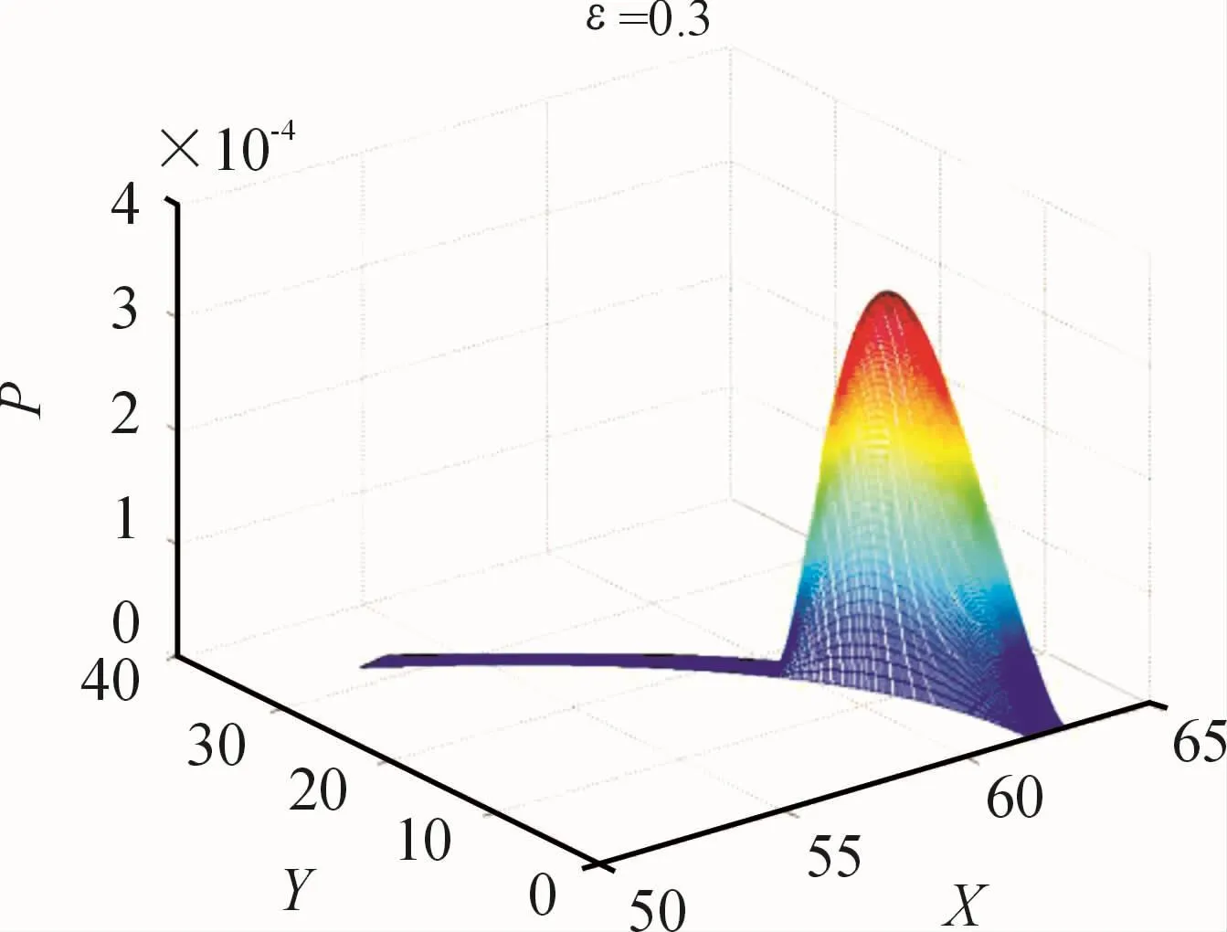
Fig.7 Pressure distribution on the sealing strip of the shaft
3 Dynamic model
The dynamic model describes the axial and radial dynamics of the distribution shaft,including the force balance equation between the load force and supporting force.The supporting force can be obtained by integrating the pressure distribution obtained the lubrication model.
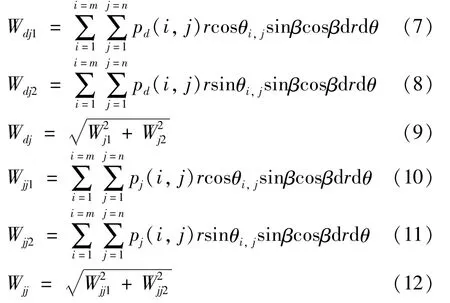
The bearing force from dynamic pressure(pd(i,j))and squeeze pressure(pj(i,j))in the axial direction is:

The bearing force from dynamic pressure and squeeze pressure in the radial direction is:
When the working pressure phincreases suddenly,the pressure of oil in high pressure damping grooves(p2and p′2)not increases with it immediately and there is a process of pressure increment.For this reason,the force balance state brakes and the spindle begins to move.The movement of spindle causes thechange of pressure distribution in the oil gap,and then the changed force willreact upon the movement again.So this is a coupling process of change.The process of pressure building in grooves can be described by the equations below:

where the flow from outlet to high pressure groove is represented by Qin,the flow leaked from the groove caused by pressure difference and squeezing are represented by Qout1and Qout2.
The load in the axial direction can be got by this equation:

So,considering the support force of oil,pressure building in grooves and the load,we can conduct the dynamic model of the spindle in axial and radial direction as:

4 Theoretical results and discussion
In the practical working condition,the load impact usually takes place instantly.So we can use step signal to simulate the load impact when solving dynamic equations.When load impact is2 MPa,we can obtain the change trend of pressure in high pressure damping groove shown in Fig.8.
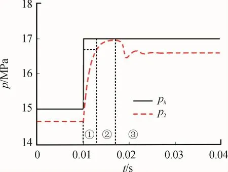
Fig.8 Pressure build-up in high pressure grooves
When working pressure increases suddenly,the balance of forces in radial direction breaks and the spindle starts to move.So the oil in gap is squeezed and the pressure in groove increases quickly and achieves the final steady pressure in nearly 0.002 second as shown in①in Fig.8.In this stage,¨x>0 and the spindle does an accelerated movement so can be called rapid rise stage.Then,the support force from damping groove and dynamic pressure increases continuously and the speed of spindle decreases gradually and gets 0 finally.At the same time,pressure in damping groove achieves the maximum value.We call this process as overshoot stage shown in②.At the end of this stage,x=0 and¨x<0,so the spindle starts to move in opposite direction and when speed decreases to 0 the spindle move to the original direction again.In this process,the position of spindle fluctuates up and down then gets steady,such as the pressure in damping groove.We call this process as stable regulation stage(shown in③)and the end of this stage is also the end of dynamic movement of spindle.
When working pressure increases suddenly,the spindle moves not only in radial direction but also in axial direction.We can obtain the position of spindle’s center every time through dynamic model’s solution as is shown in Fig.9.When the impact happens,the spindle moves down as analyzed above so the eccentricity increases with it.Higher eccentricity causes higher dynamic pressure so the support force in axial direction is bigger than load and the spindle does accelerated movement.Then dynamic pressure weakens with the damping oscillation in radial direction and the speed in z axis decreases to 0.This process is described by black line in Fig.9.

Fig.9 Orbit of shaft center whenΔp=2 MPa
When the displacement of spindle in z axis achieves the maximum,the load is bigger than support force and the spindle starts to move in opposite direction until back to the original position.At the same time,the spindle gets back to balance position,too.This process is described by red line in Fig.9.Based on the track of spindle,we can know that when load im-pact happens,the conical spindle can change pressure distribution by regulate its position so that it can achieve balance state again.We can call this regulation process without external force as self-adaptive lubricating characteristic.
We can use two parametersεand h0to describe the dynamic reputation process.The eccentricityεcan be solved by the equation:

Whenε=0,the axis of spindle and cylinder is coincide,and whenε=1,the spindle is contact with cylinder.
Concentric gap h0means the gap’s thickness when ε=0.If the value of h0is too small,the spindle is contact with cylinder easily and causes wearing.In the other hand,if the value of h0is too big,the leakage will be much and volumetric efficiency is low.We can obtain the value of h0by the equation:

Then we analyze the dynamic characteristics of conical spindle flow distribution in these working conditions:working pressure is 15 MPa,rotating speed is 1 500 r/min,and impact pressure is 2 MPa,5 MPa and 10 MPa.
The whole changing process of h0is shown in Fig.10 and the initial time is shown in Fig.11.From the figure we can see that the range of eccentricity is obviously wide and the peak value is nearly 0.8 of 5 MPa pressure impact compared to 2 MPa case.It means that higher pressure impact causes more seriously fluctuation of spindle in radial direction.However,there is no obvious difference compared with 10 MPa pressure impact because the peak value ofεis close to the limit.So frication and wear take place more easily with larger pressure impact and 5 MPa or more is a dangerous condition.
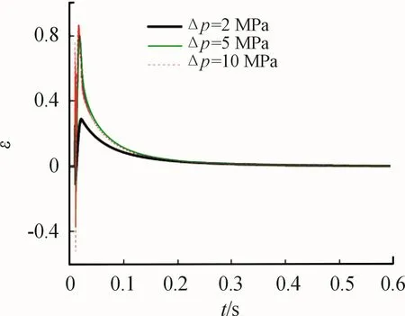
Fig.10 Dynamic change of eccentricity at step pressure
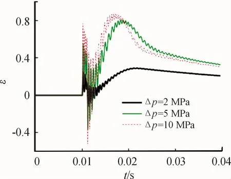
Fig.11 Enlarged dynamic change of eccentricity at step pressure
The changing trend of h0is shown in Fig.12 and Fig.13 and reflects the self-adaptive reputation of the flow distribution pair well.We can see that the peak value of 5,10 MPa pressure impact is 1.6 times as high as2 MPa pressure impact.Such large h0may appear that ball piston pump can’t work effectively because of leakage.
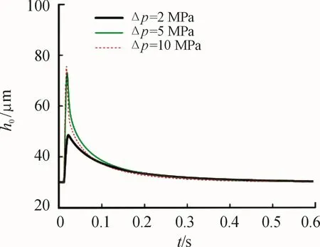
Fig.12 Dynamic change of oil film thickness
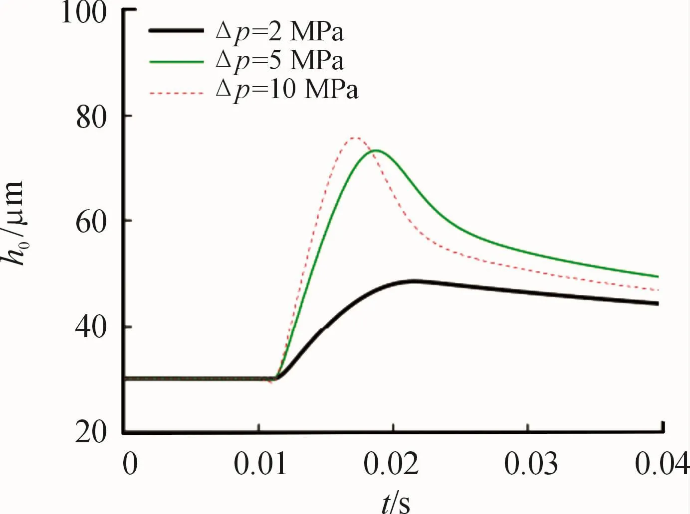
Fig.13 Enlarged dynamic change of oil film thickness
In order to observe whether the wear exist in dynamic changing,we define hminas the minimal gap between spindle and cylinder.It can be got byεand h0:

The changing trend of hminwith time is shown in Fig.14.As we have seen,the higher the step pressureis and the lower the hminis.WhenΔp are 2 MPa,5 MPa and 10 MPa,the minimal value of hminare 22μm,15μm and 7μm.Considering machining level and the size of granule in oil,the spindle is very likely contact with cylinder with the gap of 7μm.In a word,we should avoid high pressure impact to ensure the pump can work healthily.
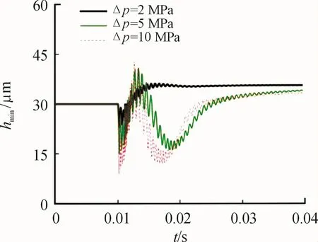
Fig.14 Dynamic change of minimum oil film thickness
Different rotating speed makes great effect to dynamic pressure and lubricating characteristics.We will analyze the effect of rotating speed in the working condition of ph=15 MPa,Δp=5 MPa.
The changing trend ofεand h0with rotating speed 500,1 000 and 1 500 r/min are shown in Fig.15 and Fig.16.Through comparing three conditions,we can know that when rotating speed increases,the amplitude of h0increases and the amplitude ofεdecreases.The reason is that rotating speed can improve dynamic pressure,so the trust force in z axis increases and the displacement increases,too.At the same time,the improvement of dynamic pressure enhances the stiffness of oil in x axis.So,higher rotating speed can help to improve the stability of the work.
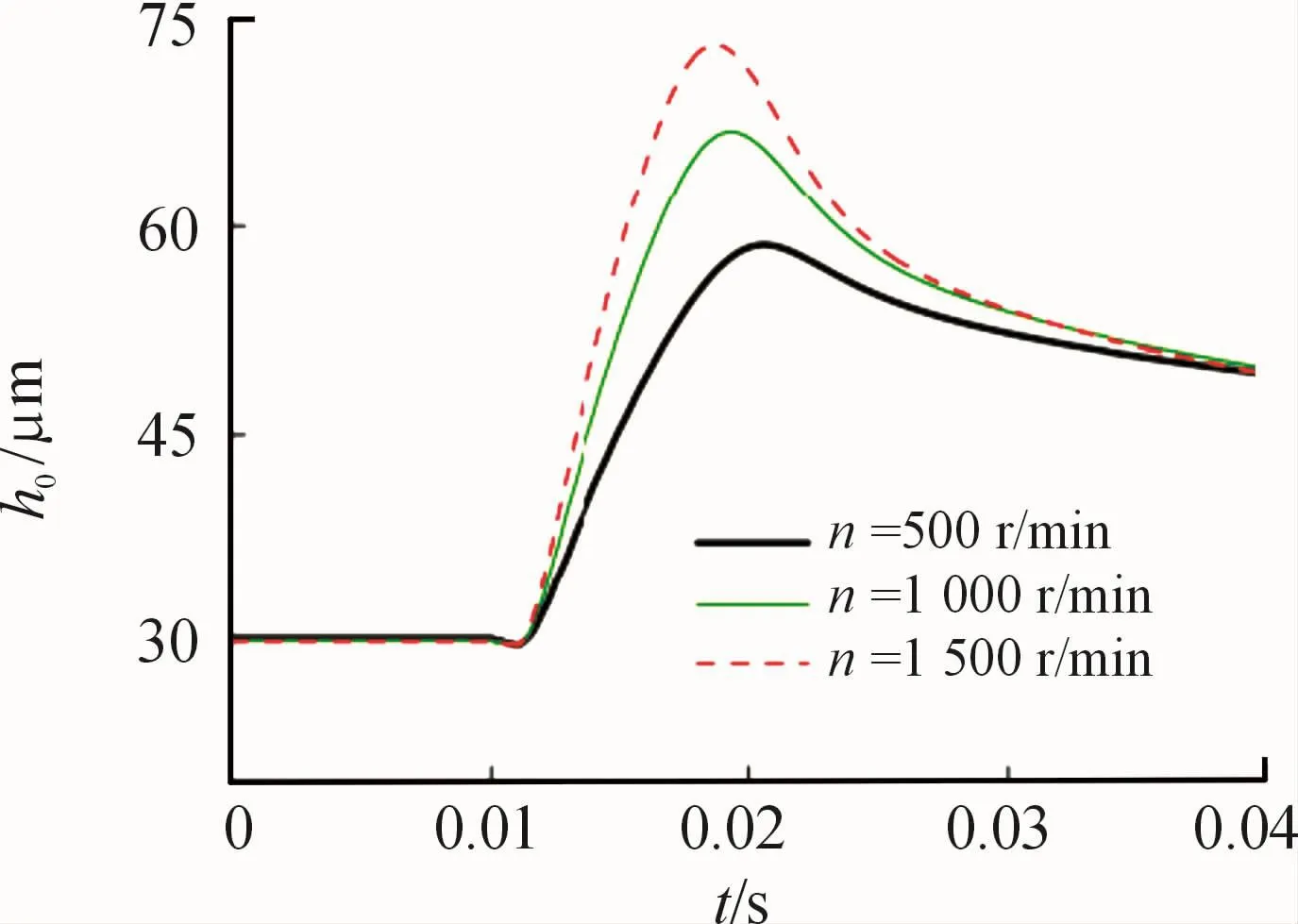
Fig.15 Eccentricity and oil film at different speeds
Based on the changing ofεand h0,we can obtain the trend of hminshown in Fig.17.There is little difference compared with three conditions,but the lower rotating speed is,the lower hminis.So,in a word,high pressure impact,low rotating speed is the most dangerous condition and we should try to avoid it.
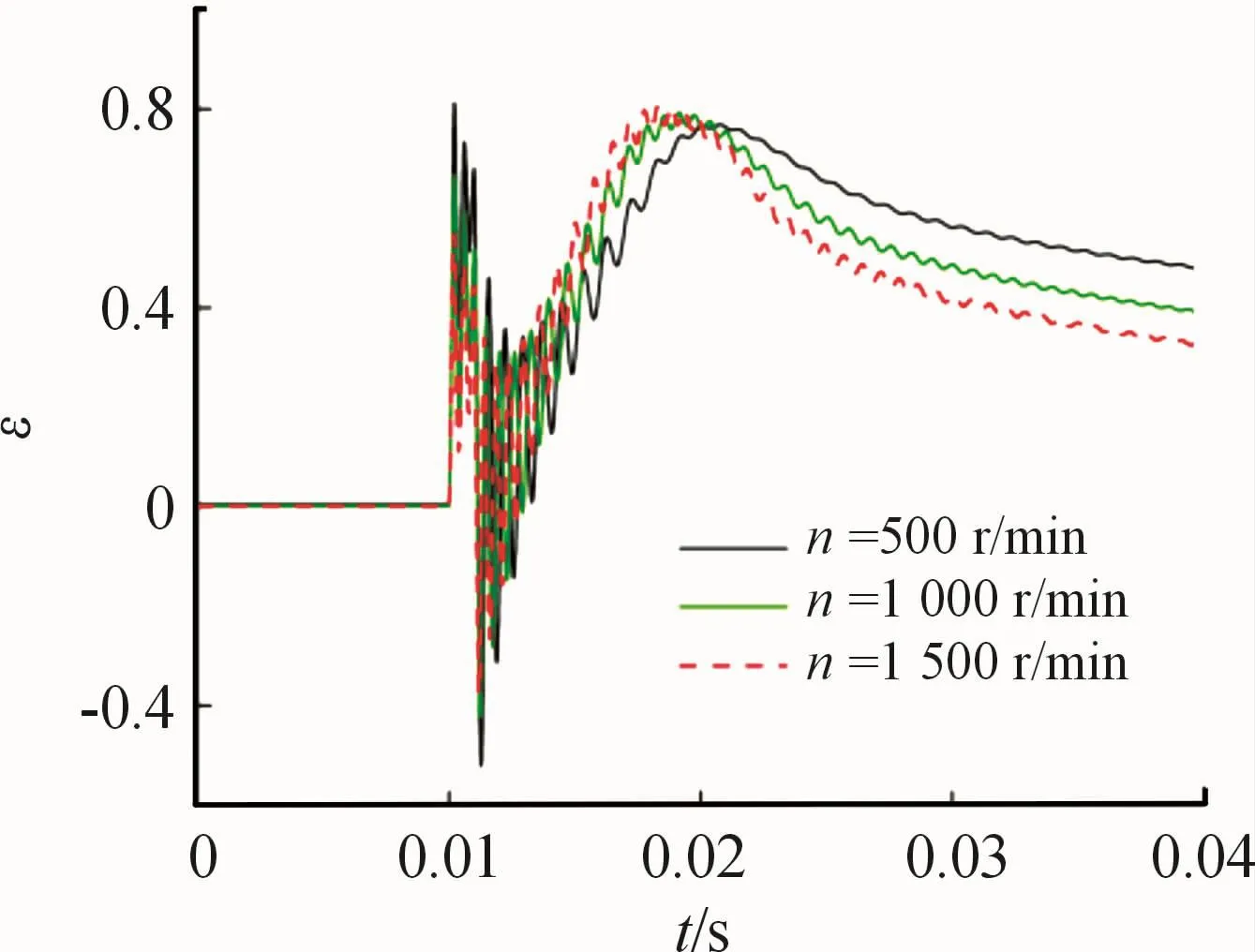
Fig.16 Eccentricity and oil film at different speeds
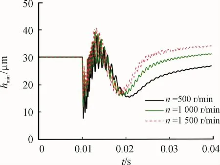
Fig.17 Minimum oil film thickness
5 Conclusions
In this paper,we build the lubricating model of conical spindle flow distribution pair,in the model the pressure building in high pressure damping groove is considered.Based on this,we can obtain pressure distribution in the gap in every position of conical spindle.Then the dynamic model of distribution shaft in radial and axial direction is constructed and the position of spindle can be investigated through numeral solution.The main conclusions are:
1)When the impact pressure is exerted,there are three stages of pressure in high pressure groove:rapid rise,overshooting,and stable regulation.Compared with working pressure,the rise of the pressure in groove is delayed and it causes the complex process of force and movement.
2)When the impact pressure is exerted,the spindle moves down with damping oscillation in radial direction and is pushed away from cylinder in axial direction.After achieving the farthest position,thespindle goes back to the original position.It’s a selfadaptive process.
3)High pressure impact makes the dynamic process more serious and the peak value of eccentricity and oil film thickness larger,which reduces the operating stability.High rotating speed makes the peak of oil film thickness larger,eccentricity smaller,and improves the operating stability.So,high pressure impact,low rotating speed is the most dangerous condition and it should be avoided.
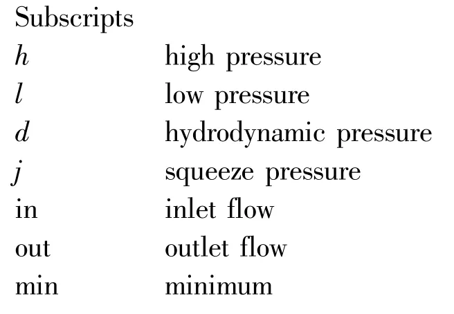
Nomenclature

- 机床与液压的其它文章
- Mechanism analysis and control of asymmetrical digital cylinder
- Reliability analysis and calculationof the drive hydraulic system group of combined transportation
- Reliability analysis for cutterhead hydraulic drive system of remanufactured shield machine
- Application of compound buffer hydraulic cylinder in electro-hydraulic load simulator(EHLS)
- Start-up characteristics of a new electro hydrostatic actuator with an accumulator
- Research on dynamic characteristics of vehicle shifting buffer valve

