Research on dynamic characteristics of vehicle shifting buffer valve
Qi-hui ZHANG,Wei XIONG,Jian-ping TANG,Zu-wen WANG
(1School of Mechanical and Electrical Engineering,JiangXi University of Science and Technology,Ganzhou 341000,China)
(2Ship Electromechanical Equipment Institute,DaLian Maritime University,Dalian 116026,China)
(3 School of Mechanical and Electrical Engineering,Central South University,Changsha 410083,China)
Abstract:A vehicle shifting buffer valve is the research object in this paper,and a mathematical model of its work process is established.The influence of its structure parameters on the buffering pressure characteristics is analyzed by Matlab/simulink.Results show that the impact of the diameter of its buffer spool and throttling orifice on the buffering pressure characteristics is larger,and the stiffness of the buffer spring and the return spring have some influence on the buffering pressure characteristics.
Key words:Shifting buffer valve,Dynamic characteristics,Matlab,Vehicle
1 Introduction
In the process of a vehicle shifting,the shift clutch’s friction elements in the engagement and disengagement have a slippage process,inevitably accompanied torque disturbance.It produced a shift shock,affecting the smoothness of the vehicle shifting.During the process of the vehicle shifting,it needs to ensure that there is a reasonable hydraulic pressure characteristic in clutch oil chamber in order to enhance the smooth shift and the speed of the vehicle has a smooth transition.[1-2]In fact,using different control principles and structures,there are many the clutch hydraulic control methods.[3-6]Currently,the usual measure is that introduction of a hydraulic buffer valve controls hydraulic clutch oil chamber in the oil line for vehicle shifting.
Many domestic scholars are studying and seeking ways to improve the vehicle shifting smoothness,especially have done a lot of research on the hydraulic buffer valve.Ma Biao[7-8]have designed the different orifice flow area of the hydraulic buffering valves for vehicle shifting.Be able to adjust the buffer time of the shifting process and use of the dynamic mathematical model analysis buffer valve,under the conditions of the structure and processing accuracy which are allowed,it should increase the diameter of the hole feedback and reduce the amount of overlapping of feedback oil hole diameter with buffering valve core.Lv Qingjun[9-10]use AMESim to analyze the dynamic characteristics of a vehicle buffering valve for vehicle shifting.The results show that the key factors which affect the dynamic characteristics of the buffering valve are the diameter of the hole feedback,buffer spring stiffness and its preload.Lin Feng[11]apply an electro-hydraulic proportional decompressing valve which is produced by VICKERS and a dynamicmath model was created.A close-loop control of the electro-hydraulic buffering control in the vehicle transmission was realized.
The composition and working principle of a hydraulic buffering valve for vehicle shifting is introduced.A mathematical model of its work process is established.The impact of the diameter of the buffer valve’spool,the diameter of the buffer valve’orifice,the stiffness of the buffer spring and the stiffness of the return spring on the buffering pressure characteristics are researched.
2 The structure and working principle of the hydraulic buffering valve for vehicle shifting
Structural diagram of a vehicle for shifting buffer valve shown in Fig.1.By coordinating the work of buffer spool,buffer spring,plunger and return spring,a buffer spring and the return spring are mounted on both sides of the plunger.There is a throttling orifice which connected with the inlet oil chamber and the inner cavity of the buffer spool in the buffer spool.There are a drain throttling orifice and a drain slotted hole in the middle of the valve sleeve,and both ends of the valve sleeve have drain port.
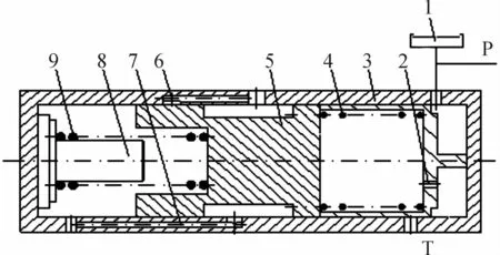
Fig.1 The structure schematic diagram of the hydraulic buffering valve
When the vehicle starts to shift,the drain port is unopened.The oil flows rapidly into the clutch oil cylinder,eliminate the gap between the friction disks until the friction disks fit.Then oil through the buffer spool 2 into the inner cavity of the buffer spool and push the plunger 5 moves slowly.The drain port is opened.The pressure of the clutch oil cylinder slowly rises under the action of the buffer spring and the return spring until the plunger is resisted by the limit column.The pressure of the clutch oil cylinder quickly rises to the main pressure.
3 The dynamic math model of the system
3.1 Model assumptions and symbols
Before the model is created,it assumes:The system operates at steady state;the inertia of the hydraulic buffering valve is ignored;the fluid viscous resistance and the mechanical friction are negligible;the leakage and the centrifugal hydraulic thrust are ignored.
To be convenient for the mathematical model of the hydraulic buffering valve established,the symbols,which is used in the derivation of the math model,are shown in Fig.2.Explained its meaning as follows:
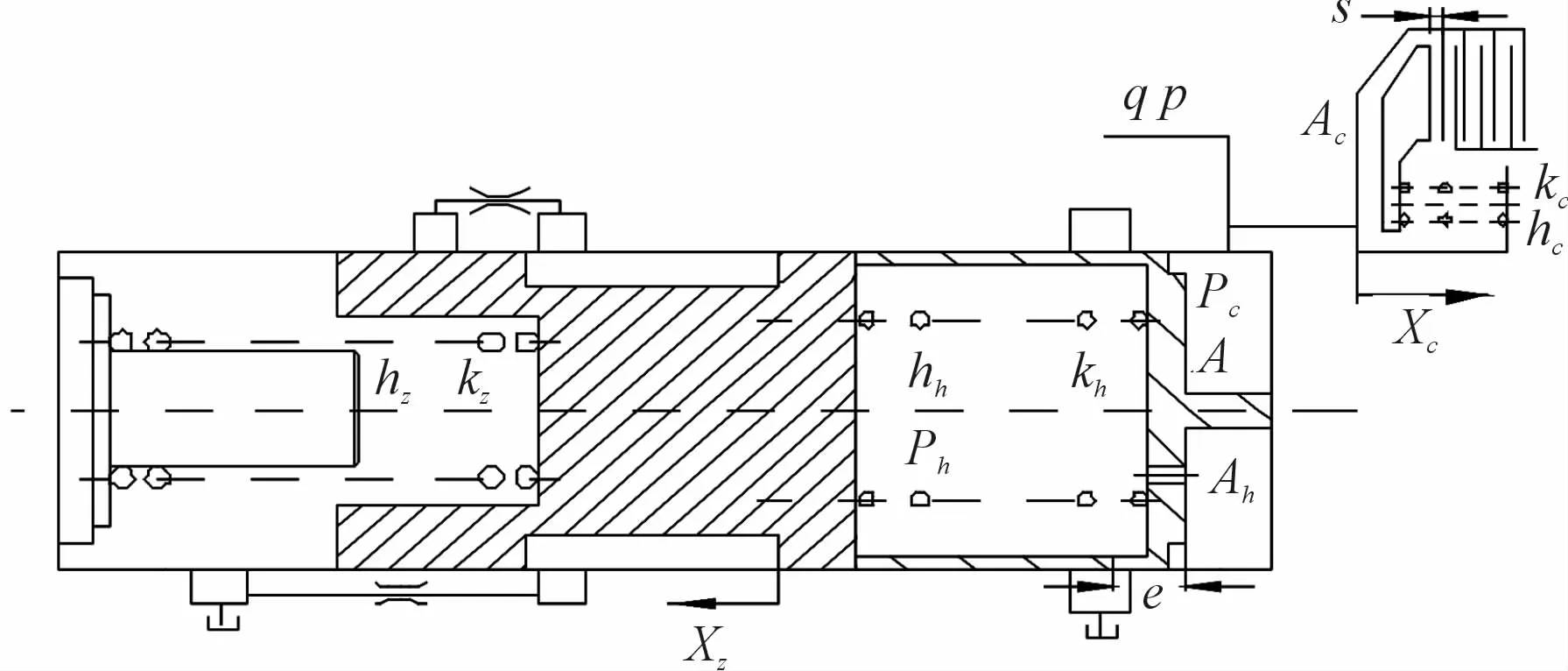
Fig.2 The structure schematic diagram of the hydraulic buffering valve
q is the flow rate through the oil line;ρis density of hydraulic oil.
Parameters related to the clutch:PCis the pressure of the clutch oil cylinder;ACis the area of the clutch piston;KCis the stiffness of the clutch spring;hCis the pre-compression of the clutch spring;XCis the displacement of the clutch piston;s is freedom displacement of the clutch piston.
Parameters related to the buffer spool:A is the cross-sectional area of the buffer spool;Cdhis the flow coefficient of the throttling orifice;Ahis the cross-sectional area of the throttling orifice;Khis the stiffness of the buffer spring and the stiffness of the return spring;hhis the pre-compression of the buffer spring;e is the amount of overlapping of the buffer spool with the drain port;Phis the pressure of the inner cavity of the buffer spool.
Parameters related to the plunger:KZis the stiffnessof the return spring;hZis the pre-compression of the return spring;XZis the displacement of the plunger.
3.2 The dynamic math model of the pressure characteristics
According to the working principle of the hydraulic buffering valve for Vehicle Shifting,the clutch charge process can be divided into three stages,Rapid oilcharge stage,Buffer Pressure Rise Stage,and step Pressure Rise Stage.Therefore,The math model of the buffering pressure characteristics are established according to these stages.
1)Rapid oil-charge stage
At this stage it’s mainly to overcome the clutch spring preload.The pressure of the clutch oil cylinder is determined by the clutch spring and the area of the clutch piston.Accordingly,mathematical model can be established at this stage.
Clutch piston force balance equation

The displacement of the clutch piston and the flow rate through the oil line establish the equation

The pressure of the clutch oil cylinder is

2)Buffer pressure rise stage
At this stage the pressure of the clutch oil cylinder slowly rises under the action of the buffer spring and the return spring.The pressure of the clutch oil cylinder is determined by the return spring and the crosssectional area of the plunger.
The buffer spool force balance equation

The plunger force balance equation

The displacement of the plunger and the flow rate through the throttling orifice establish the equation

The pressure of the clutch oil cylinder is

3)Step pressure rise stage
After termination of the buffer stroke,the clutch is fully pressed and engages together.The pressure of the clutch oil cylinder quickly rises to the main pressure.
4 The analysis of simulation results
4.1 The Matlab model of the hydraulic buffering valve
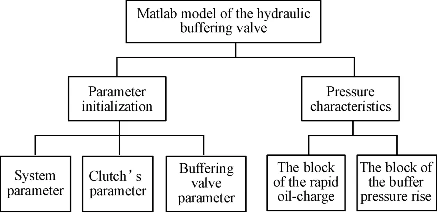
Fig.3 Program structure
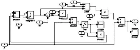
Fig.4 The block diagram of the buffer pressure rise stage
4.2 The simulation results of engagement process
In this paper,the flow coefficient and the density of hydraulic oil are not affected by the temperature.So the flow coefficient is approximately constant Cdh≈0.65,the density of hydraulic oil is 860 kg/m3.the main pressure is1.375 MPa,the flow rate through the oil line is 40 L/min.
The stiffness of the buffer spring is 12 N/cm,10 N/cm,8 N/cm.The stiffness of the return spring is 85 N/cm.The cross-sectional area of the buffer spool is 17 mm.The cross-sectional area of the throttling orifice is 1 mm.These data input the module of the parameter initialization.Run the simulation,drawing the curve as shown in Fig.5.In the curve,the horizontal axis represents the time t,which unit is second s;The vertical axis represents the hydraulic.From Fig.6 to Fig.8,the coordinate axes have thesame meaning as it,not repeat them.
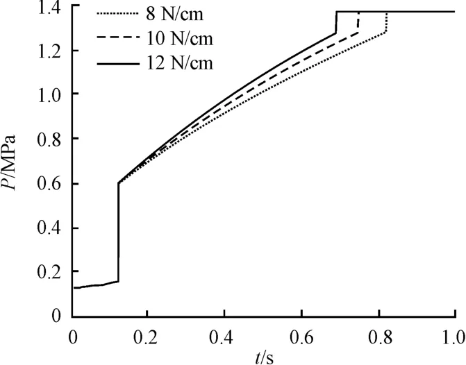
Fig.5 The stiffness of the buffer spring on the buffering pressure characteristics
As it can be seen from the curve,With the increase of the stiffness of the buffer spring,In Buffer Pressure Rise Stage.Hydraulic rises faster,the rise time reduces,the shorter the shift buffer time.
The stiffness of the return spring is 85 N/cm,75 N/cm,65 N/cm.The stiffness of the buffer spring is 8 N/m.The cross-sectional area of the buffer spool is 17 mm.The cross-sectional area of the throttling orifice is 1 mm.These data input the module of the parameter initialization.Running the simulation,draws the curve as shown in Fig.6.
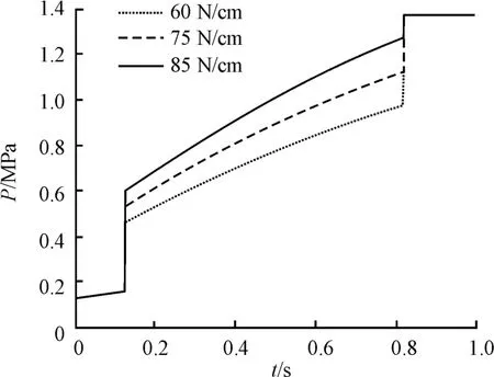
Fig.6 The stiffness of the return spring on the buffering pressure characteristics
As it can be seen from the curve,with the increase of the stiffness of the return spring.In Buffer Pressure Rise Stage,the pressure increases gradually,but it didn’t affect the shift buffer time.
The cross-sectional area of the buffer spool is 17 mm,19 mm,21 mm.The stiffness of the buffer spring is 8 N/m.the stiffness of the return spring is 85 N/cm.The cross-sectional area of the throttling orifice is 1 mm.These data input the module of the parameter initialization.Running the simulation,draws the curve as shown in Fig.7.
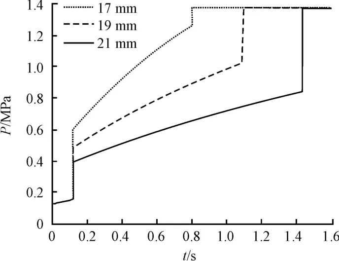
Fig.7 The cross-sectional area of the buffer spool on the buffering pressure characteristics
As it can be seen from the curve,with the increase of the cross-sectional area of the buffer spool.In Buffer Pressure Rise Stage,Hydraulic rises faster,the rise time reduces,the shorter the shift buffer time.
The cross-sectional area of the throttling orifice is 1 mm,2 mm,3 mm.The stiffness of the buffer spring is 8 N/m.the stiffness of the return spring is 85 N/cm.the cross-sectional area of the buffer spool is 17 mm.These data input the module of the parameter initialization.Run the simulation,draws the curve as shown in Fig.8.
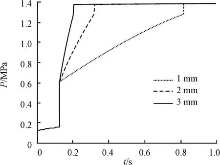
Fig.8 The cross-sectional area of the throttling orifice on the buffering pressure characteristics
As it can be seen from the curve,with the increase of the cross-sectional area of the throttling orifice.In Buffer Pressure Rise Stage,hydraulic rises faster,the rise time reduces,the shorter the shift buffer time.
5 Test verification
In order to verify the results of the simulation mod-el,an experimental study on the hydraulic pressure characteristic test platform of the buffer valve shown in Fig.9 was carried out.
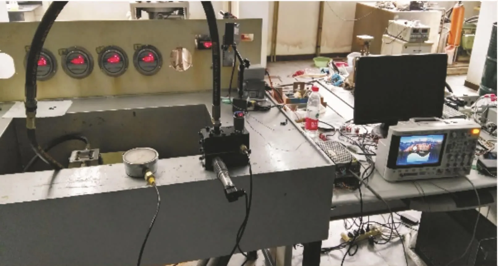
Fig.9 Experimental platform of the buffering characteristic of the buffering valve
In this buffering process,it is necessary to collect and record the inlet and outlet pressure and flow of the buffer valve to obtain the oil pressure characteristic curve of the buffer valve.The experimental results and simulation curves are shown in Fig.10.
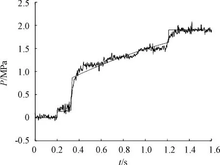
Fig.10 Test and simulation comparison curve
Fig.10 shows a comparison curve between the test results and the simulation results.It can be seen that the simulation results and the test results are in the same trend.Therefore,the Matlab mathematical model of the buffer valve can reflect the pressure characteristics of the valve,and the model has an accuracy.It can also be seen from the figure that the test time of the valve in the buffer stage is about 0.825 s,the simulation time is 0.875 s,and the relative error of the buffer time is 5.3%;after the Step Pressure Rise Stage,the output pressure test result of the buffer valve is 1.997 MPa,the simulation result is 2.003 MPa.
6 Conclusions
A mathematical model of the hydraulic buffering Valve is established.Then use of Matlab analyzed the influence of its structure parameters on the buffering pressure characteristics.The results show:
1)The stiffness of the buffer spring is 12 N/cm,10 N/cm,8 N/cm.Other parameters are the same.The buffer time of the shifting process is 0.693 s、0.747 s、0.820 s.The stiffness of the return spring is 85 N/cm,75 N/cm,65 N/cm.All the buffer time of the shifting process is0.820 s.The cross-sectional area of the buffer spool is 17 mm,19 mm,21 mm.The buffer time of the shifting process is 0.820 s、1.021 s、1.483 s.The cross-sectional area of the throttling orifice is 1 mm,2 mm,3 mm.The buffer time of the shifting process is 0.820 s、0.323 s、0.204 s.
2)The results show that the impact of the diameter of its buffer spool and throttling orifice on the buffering pressure characteristics is larger,and the stiffness of the buffer spring and the return spring have some influence on the buffering pressure characteristics.The impact of the diameter of the throttling orifice on the buffering pressure characteristics is more obvious.The stiffness of the return spring has great influence on the pressure in buffer pressure rise stage.So reasonable optimization of the diameter of the hydraulic buffering valve’s buffer spool,throttling orifice and spring stiffness,can obviously improve the dynamic characteristics of the hydraulic buffering valve.
- 机床与液压的其它文章
- Lubricating performance of conical spindle distribution in the ball piston pump
- Mechanism analysis and control of asymmetrical digital cylinder
- Reliability analysis and calculationof the drive hydraulic system group of combined transportation
- Reliability analysis for cutterhead hydraulic drive system of remanufactured shield machine
- Application of compound buffer hydraulic cylinder in electro-hydraulic load simulator(EHLS)
- Start-up characteristics of a new electro hydrostatic actuator with an accumulator

