Mechanism analysis and control of asymmetrical digital cylinder
Hao-yu ZHU,Zhong-cai PEI,Hong-lin LIU,Peng JIANG,Zhi-yong TANG
(1School of Automation Science and Electrical Engineering,Beihang University,Beijing 100191,China)
(2 Army Representative Office in Nanjing,Nanjing 210000,China)
Abstract:The asymmetrical digital hydraulic cylinder with double thread pair structure is designed,and the working mechanism is analyzed.The digital cylinder model is built by AMESim,and the simulation of asymmetric digital cylinder that is controlled by the symmetric valve and theasymmetric valve is carried out respectively under no-load and constant force load.The resultsprovethat,during reversing,the pressure jump can be eliminated by applyingthe asymmetric valve.Especially,when the cylinder extends under negative load,cavitation can be avoided by the asymmetric valve.It provides a useful attempt for the optimal design of the digital cylinder.
Key words:Asymmetrical hydraulic cylinder,Digital hydraulic cylinder,Asymmetrical valve,Simulation on AMESim
Asymmetric hydraulic cylinder,also known as single-rod cylinder,has been widely applied in construction machinery,bridge erectionand emergency road access equipment for its compact structure.The mechanical feedback asymmetric digital cylinder can directly be controlled by inputting the pulse signal to the stepper motor driver.Bycontrolling the rotation angle and speed of the stepper motor,it is easy to realize the position and speed control of the cylinder,thus reducing the difficulty of the debugging of hydraulic cylinder control system.Being a typical mechanical hydraulic servo system,the digital hydraulic cylinder is convenient to be utilized.Digital cylinder has low requirements for oil cleanliness and high-cost performance,because it is controlled by spool valve.However,traditional simulation analysis method based on transfer function is difficult to simulate the real situation of cylinder operation[1-2]due to the serious nonlinearity in the system,thus resulting in a certain deviation in the case of large load pressure.On the other hand,it is not easy to analyze the pressure and flow of two chambers of hydraulic cylinder.Xiao Zhiquan[3]established the nonlinear state equation model of the system for digital cylinder,but did not consider the influence of valve and cylinder leakage,leading to large reversing deadband.Guo Hongbo[4]established the general nonlinear state equation of valve controlled hydraulic cylinder system,and based on thisstate equation,heanalyzed the deadband and inconsistent opening that are caused by valve processing error,thus leading to the change of hydraulic system characteristics.With the development of computer simulation technology,AMESim software can directly solve the non-linear differential equation of valve controlled asymmetric cylinder[10],and the simulation results can directly simulate the flow rate,the pressure of two chambers and other variables changing with time.So the control characteristics of valve con-trolled asymmetric cylinder can be simulated directly.
Without the external position sensor,digital cylinder system cannot dynamically adjust the angle of the stepping motor based on the position of the piston rod to adjust the opening of the valve,so as to ensure the dynamic characteristics of the digital cylinder under different load conditions[9].The digital cylinder hydraulic servo system must have a good control performance.Therefore,AMESim is applied to simulate and analyze the performance of symmetrical valve and asymmetric valve controlled asymmetric digital cylinder under no-load and constant load conditions,so asto test the performance of the designed system.
1 Mathematical model of valve controlled asymmetric hydraulic cylinder
The asymmetric digital cylinder is a valve controlled asymmetric cylinder servo system with mechanical feedback of piston position.The designed digital hydraulic cylinder is displayed in Fig.1.When the digital cylinder needs to move,the step motor 7 drives the connector 6 to rotate and then drives the spool 5 to rotate.The connector ensures that the rotation of the spool is synchronous with the step motor.Meanwhile,it does not hinder the axial movement of the spool.The spool is connected with connector 4 through a threaded pair.The spool moves in the axial direction with spool rotating,resulting ina certain opening of the spool valve.The hydraulic oil pushes the piston to move by the spool valve.The movement of piston 1 drives the movement of the ball screw nut 3 that connects with it.The ball screw 2 and the lead screw nutare not self-locking.At this time,the movement of the lead screw nut drives the lead screw to rotateand then drives the connecting shaft 4 to mechanically connect with it to rotate in the same direction as the spool,which is equivalent to the reverse rotation of the spool.So the spool moves along the direction of the valve orifices closing until the valve orifices are closed,thus leading to the fact that the hydraulic cylinder is positioned in a new position.With the rotation of the stepping motor,the linear movement of the oil cylinder can be realized.In terms of the working process of the digital cylinder and the structure of the spool valve controlled cylinder.Compared with traditional valve controlled servo cylinder,the position feedback of the digital cylinder is realized by the mechanical feedback mechanism(double thread pair).Therefore,as the traditional servo system analysis method,the model of the valve control asymmetric cylinder is established first to explore the way for the improvement of the performance of the digital cylinder.

Fig.1 Principle prototype of digital cylinder
The structure diagram of valve controlled asymmetric cylinder power mechanism is illustrated in Fig.2.It is assumed that the spool valves are matched,but the area gradient of each valve orifice may not be equal.
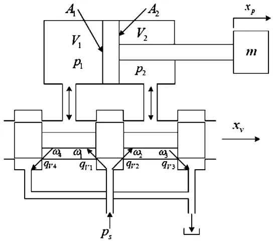
Fig.2 Valve controlled asymmetric cylinder power mechanism
Ignoring the internal and external leakage of oil,the flow continuity equations of hydraulic cylinder are as follws[7-8]:
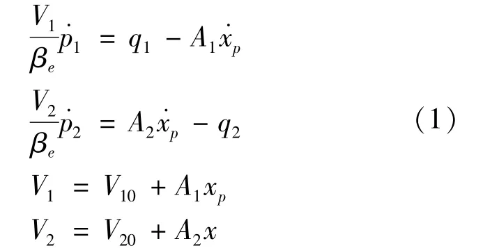
Where xpis the cylinder position,βerefers to the effective bulk modulus.A1and A2represent the annulus areas of two cylinder chambers,p1and p2stand for the pressures inside the two cylinder chambers,V10and V20mark the initial control volumes of two chambers,q1and q2mean the flows inside two cylinder chambers.
Applying Newton second law,the force balance equation is described as follow:

Where m is the load mass,K stands for load springconstant,B marks the viscous damping coefficient,and FLrepresents the external load on the piston of cylinder.
The flows inside two cylinder chambers can be described as follows:When xv≥0,

and when xv<0,

Where Cdis the discharge coefficient.ω1,ω2,ω3and ω4are the area gradient of each valve orifice,xvmarks the valve spool position,andρrepresents the density of hydraulic oil.
Without considering the compression and leakage of the oil,the expression of the pressure of the two chambers can be obtained by combining(1),(2),(3)and(4).Ifω1=ω2=ω3=ω4,due to different cross-sectional areas of the two chambers,there would be pressure jump when reversing[5-6].When the position of positive and reverse spool position is the same,the steady-state speed of the piston is not the same.
According to the calculation in[6],if it is ensured that the asymmetric valve controlled asymmetric cylinder is under no load,the positive and reverse position of the spool are the same,and the pressure of the two chambers does not jump and the piston speed is the same.The area gradient of each valve orifice of the spool shall meet the following requirements:
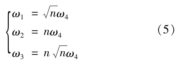
Where n=A2/A1.
In this paper,the asymmetric valve is realized by adjusting the slot width of the valve with rectangular throttling slot.
2 AMESim model of digital cylinder
Fig.3 demonstrates the AMESim model of digital hydraulic cylinder.The model of valve and asymmetric cylinder is built by the basic unit in hydraulic component design(HCD)library based on its structure.The valveis the non-circular opening spool valve,and the bao6[bao0002]spool with rectangular slot orifices in HCD library is combined.The flow forcethat is generated bythe spool ratation is ignored in the modeling.The screw pair and ball screw are modeled by the screw_nut element in mechanical library and asymmetric cylinder is composed of bap2 and baf1 element in HCD.The hydraulic pump is not exhbitedin the figure.
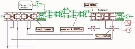
Fig.3 AMESim model of digital hydraulic cylinder
3 Simulation
Under no-load and constant force load conditions,the simulation analysis of symmetrical valve and asymmetric valve controlled asymmetric digital cylinder is carried out,respectively.The parameters of the simulation model are displayed in Table 1.
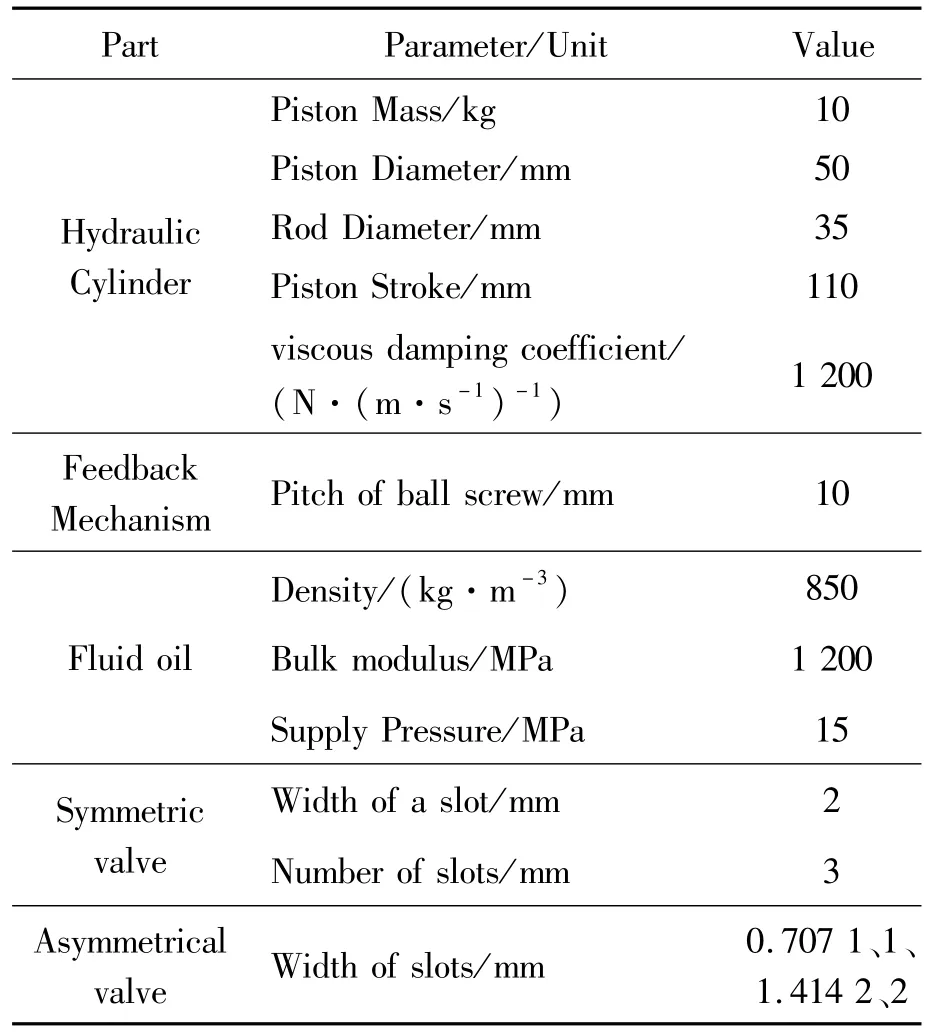
Table 1 Parameters of the physical system
3.1 No-load operation
Under no-load condition,symmetrical valve andasymmetric valve are respectively applied,so as to control the asymmetric cylinder,and the result curvesare shown in Fig.4 and Fig.5.In Fig.4,the pressure curve of the load chamber reveals that,when the symmetrical valve controlled asymmetric cylinder changes direction,the pressure of the two chambers changes,but there is no large oscillation due to the compressibility of the oil.The position curve provesthatdue to the effect of closed-loop mechanical feedback,the forward and reverse position step response curves are different,and the reverse motion response is slow,but the response time is not too different.The results in Fig.5 conclude that the pressure of the two chambers remains constant,reflecting that using asymmetrical valve to control the asymmetrical cylinder can eliminate the pressure jump when reversing.The forward and reverse characteristics tend to be the same.
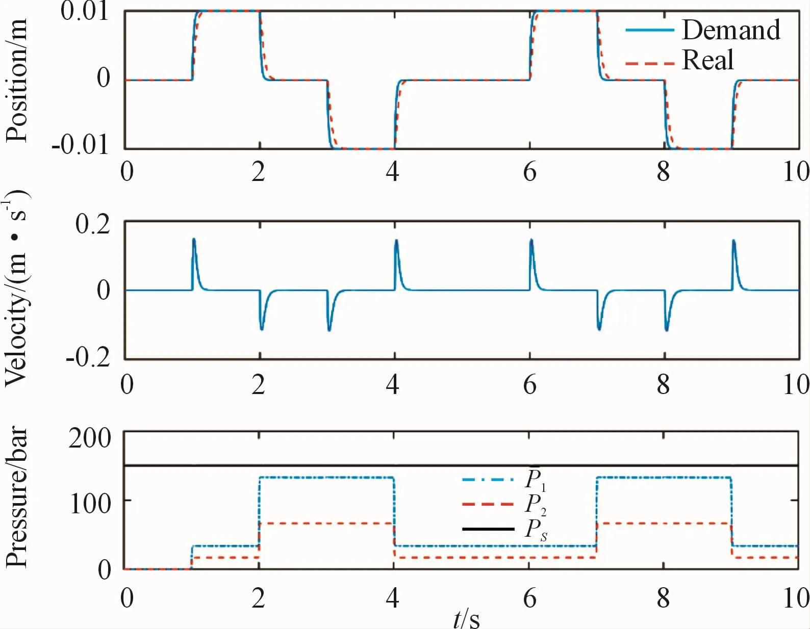
Fig.4 Response of symmetrical valve controlled asymmetrical digital cylinder in no-load operation
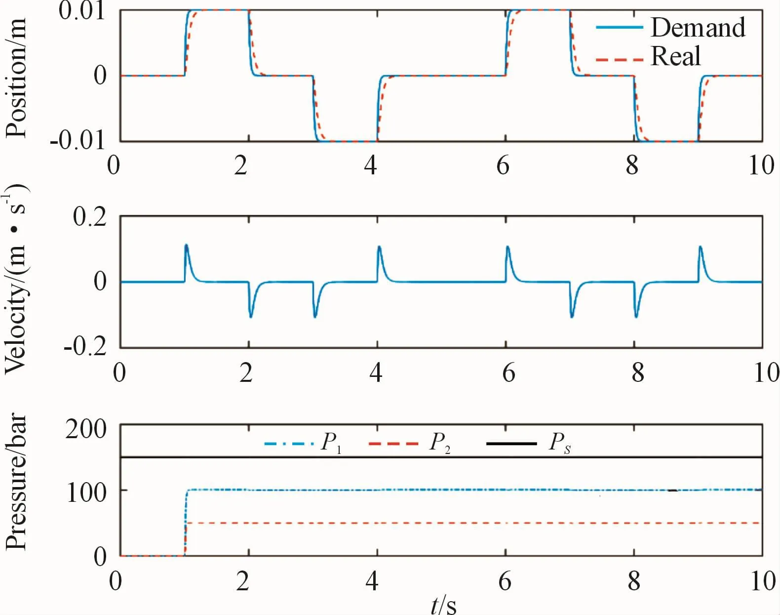
Fig.5 Response of asymmetric valve controlled asymmetric digital cylinder in no-load operation
3.2 Constant load operation
Fig.6 and Fig.7 respectively illustratethe point-topoint motion response of symmetrical valve and asymmetric valve controlled asymmetric cylinder under constant force load.In 1-5 s,8 000 N constant load is added along the retracted direction of the piston rod,while in 5.5-9.5 s,8 000 N constant load is added along the extending direction of the piston rod.The response curves of symmetrical valve is demonstrated in Fig.6.The pressure curveproves that:When the piston rod extends with negative load(6-7 s and 9-9.5 s),the pressure in the rodless chamber is less than saturated vapor pressure,indicating that cavitation occurs.The response curves of asymmetrical valveis demonstrated in Fig.7.The pressure curveshows that:Under the same load,the pressure of the two chambers will not changes rapidly,and there is no risk of cavitation.
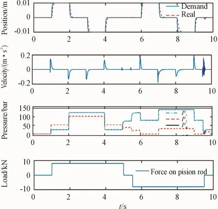
Fig.6 Response of symmetrical valve controlled asymmetric digital cylinder under constant load
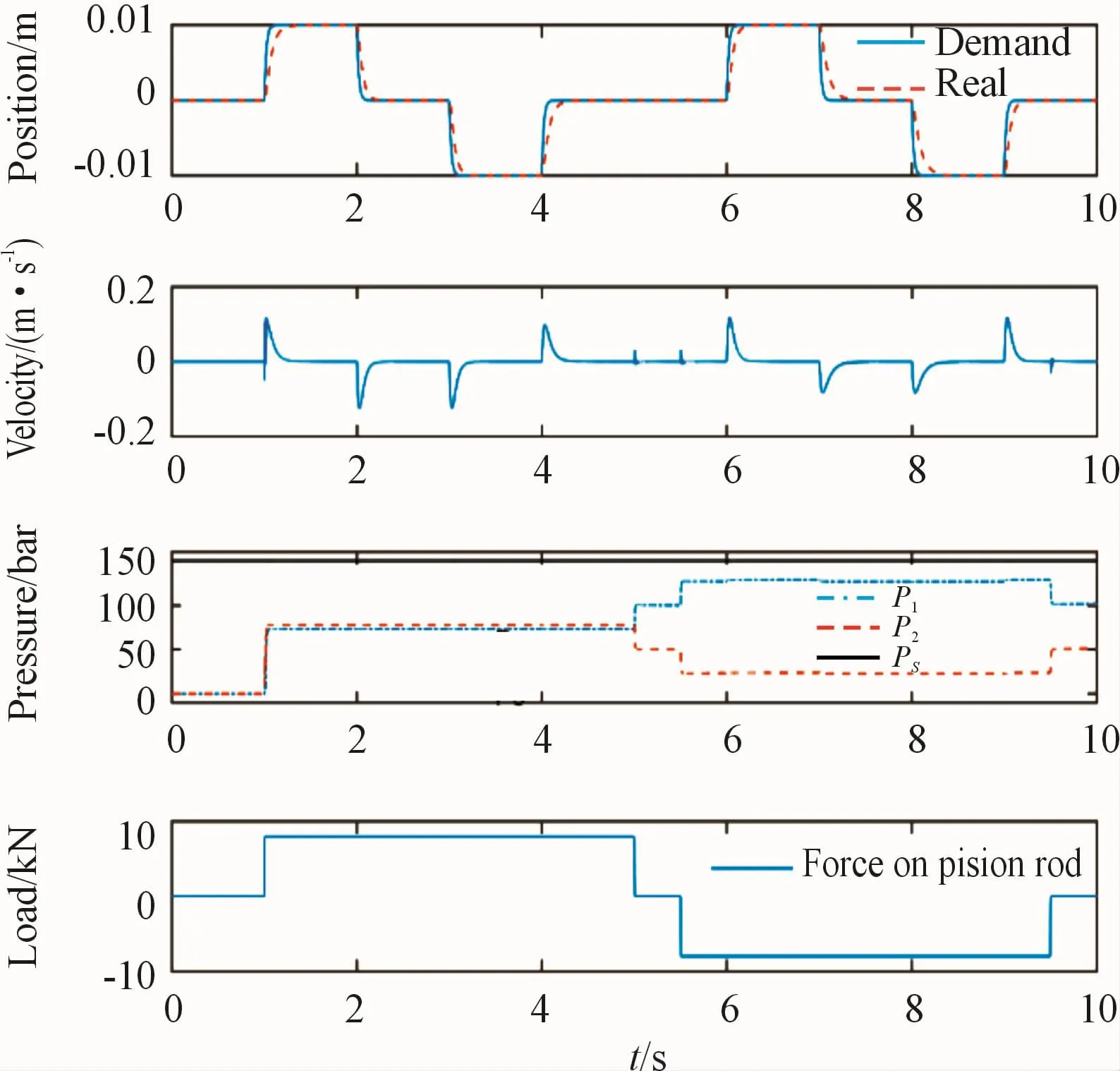
Fig.7 Response of asymmetric valve controlled asymmetric digital cylinder under constant load
4 Conclusion
In this paper,according to the design of the digital cylinder system,the theoretical analysis is carried out.A mathematical model of the valve controlled cylinder system is established.Controlled by the symmetrical valve and the asymmetric valve under the no-load and constant load conditions,the simulation analysis of the asymmetric digital cylinder is realized under the AMESim environment.The simulation results prove that,when the symmetrical valve controlled asymmetric digital cylinder is reversing,there is a pressure jump in the two chambers,but there is no large oscillation due to the compressibility of the oil.Meanwhile,due to the effect of closed-loop mechanical feedback,the positive and negative step response time is not obviously different.The results revealthat,during reversing,the pressure jump can be eliminated by asymmetric valve.Especially for cylinder extending under negative load,cavitation can be avoided by asymmetric.It lays a theoretical foundation for the engineering design of the digital cylinder.
- 机床与液压的其它文章
- Lubricating performance of conical spindle distribution in the ball piston pump
- Reliability analysis and calculationof the drive hydraulic system group of combined transportation
- Reliability analysis for cutterhead hydraulic drive system of remanufactured shield machine
- Application of compound buffer hydraulic cylinder in electro-hydraulic load simulator(EHLS)
- Start-up characteristics of a new electro hydrostatic actuator with an accumulator
- Research on dynamic characteristics of vehicle shifting buffer valve

