Optimization of cutting parameters for milling TC4 materials with spiral corn milling cutter
Shan-hua XIAO,Xian-min LOU,Rui-Qiang YAN
(Yibin Vocational and Technical College,Yibin 644003,China)
Abstract:To solve the problems of spiral corn milling cutting TC4 material force inequality and low efficiency,single blade model and cutting force model of spiral corn milling cutter were both analysed in this paper.By using AdvantEdge FEM software to set the related corn mill cutter blade structure parameters,blade parameters,and network partition,etc.we got the in-process cutting force and temperature simulation figure of spiral corn milling cutter while processing,and on the basis of these simulation parameters,process verification is conducted.The result shows that the analysis of the milling force of spiral corn milling cutter may optimize the cutting parameters,improve the efficiency of difficult-to-machine materials and reduce the tool wear of the cutters while processing TC4 materials.
Key words:Spiral corn milling cutter,AdvantEdge FEM,Cutting force model,TC4
1 Introduction
Spiral corn end milling cutter with stagger arrangement can provide better chip separating performance,reduce the cutting force of each tooth,and ease chip removal process.With the cutting thickness of each tooth increases,the cutter tooth avoids the hardened layer on the surface.Staggered cutter teeth is conducive to the penetration of cutting fluid,which is suitable for heavy cutting.It’s highly efficient and is widely used in the processing of difficult-to-machine materials.Milling force,as an important parameter in the milling process,always affects the vibration of the whole cutting system,the surface quality of the work piece and the wear condition of the cutter teeth,Therefore,it is of great significance to conduct and analyse digital modelling,to further understand the milling mechanism,to improve the design of machine tools,cutting tools and fixtures,and to optimize the cutting process parameters and geometric parameters of cutting tools.
At present,the research on cutting force model in milling process is mature both at home and abroad.For example,the linear cutting force model proposed by Altintas Y[1],which takes the dynamic cutting force as a function of the instantaneous cutting thickness.Wan Min[2]et al also put forward exponential function model.These studies are mainly focused on the overall milling cutter,but researches on cutting force model of spiral corn milling cutter are few.The cutting force model of spiral corn milling cutter is established in this paper.With AdvantEdge FEM software simulation performed,it provides a technical reference for the optimized selection of cutting parameters for spiral corn milling cutter,which improves the machining surface quality of parts,and therefore increases the machining accuracy[3-5].
2 Milling dynamics model of spiral corn end mill
2.1 Single blade mathematical model
As shown in Fig.1,define rectangular coordinate system(X,Y,Z)with milling cutter center as Z-axis,the coordinate system(u,v,w)is established with the center of the blade as the origin.Making the plane of the cutting edge coincide with the plane of the coordinate system of the blade,the vector from the tip to the center of the blade[6]is expressed as:

Where,Iris the radial offset of XY Plane,Izis the radial offset of blade center to the inner axis of the XY plane.
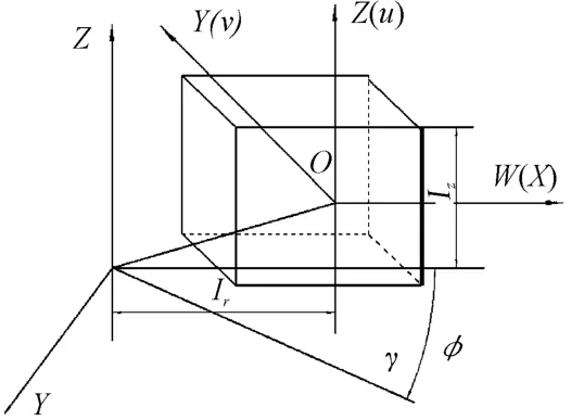
Fig.1 Location vector of blade center to the cutter
In practice,there are many shapes of blades for the different needs of blade manufacturers and machining.Typical rectangular and convex triangular blades were used for modeling analysis,as shown in Fig.2 and Fig.3.

Fig.2 Rectangular blade cutter and parameters
The blade is simplified into two parameter of Length b and Width a.The convex triangular blade can be defined by four parameters as the radius R of the arc cutting edge with Ocas the center of curvature,the distance from the center of the blade O′to the center of curvature of the cutting edge Oc,Of,plus blade boundry(θs,θe).The coordinates of any point on the cutting edge of the blade are defined by the vector in the coordinate system(u,v,w):

For the rectangular blade:-b/2≤ u≤ b/2,v=0,w=a/2.

Fig.3 Triangular blade shapes and parameters
For a convex triangular blade,the formula can be derived as[7-8](3):

Special attention should be paid to the u,v,w plane calibration of the blade surface and blade coordinate system,as shown in Fig.4,it contains cutting edge(as v=0).In the coordinate system X,Y,Z,the blade is rotated to define its position on the cutter.The rotation of blade around Y-axis leads to Angleδ,the rotation of blade around the X-axis leads to Angle β,and the rotation of blade around the Z-axis leads to AngleФ.As is shown in formula(4):
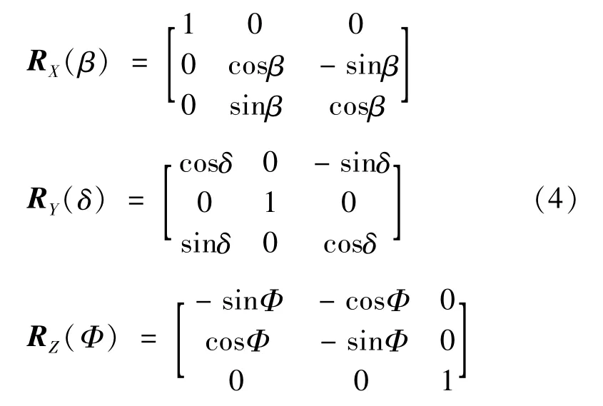
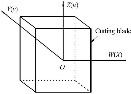
Fig.4 Tool and blade coordinate system

Fig.5 Positioning angle of corn milling cutter blade
After rotating the corn milling cutter blade around the X,Y and Z axes,the transformational matrix is as follows:
T=RX(β)*RY(δ)*RZ(Ф),then VC=T*the final position of the cutting edge in the cutter coordinate system is shown in Fig.6,as shown in equation(5):
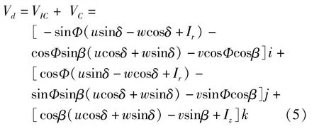
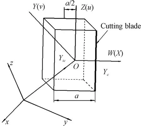
Fig.6 Final position vector of the blade
From equation(5)we can see,if the blade center point(Ir,Iz)and the rotation angle of the blade(Ф,β,δ)are both set,the blade size(a,b,R,θs,θe)and the cutting position height Z can be calculated from the above.
2.2 Modeling cutting force of spiral corn milling cutter
In the modeling of corn milling cutter’s 3d cutting edge profile and the cutting force,by dividing the blade into M micro-cutting units along the axial direction,the upper end Ph(xj,k+1,yj,k+1,zj,k+1)and P1(xj,k,yj,k,zj,k)of the kthcutting edge element on the cutting edge j can be calculated by equation(5).Parameters are as following:
1)Cutting force coefficient Ktc,Krc,Kac:cutting force coefficients in tangential,radial,and axial directions
2)Cutting microelement dFt,dFr,dFa:tangential,radial and axial cutting elements;
3)Blade force coefficient Kte,Kre,Kae:Blade force coefficients in tangential,radial,and axial directions
4)G(Фjk):Unit step function,to determine whether the current cutting edge is involved in cutting
5)dzjkrepresents microelement height;the formulation is:

6)dsjkismicro blade length,the equation is

7)Фjkrepresents micro radial contact Angle,defined as:

or

In(6),there are two milling methods:down milling and up milling.When using down milling,it is stable and the machining quality is good,the cutting in and out angle can be described asФst=л-arccos(1-ae/R)orФex=л;When using up milling,the stability is poor,and the cutting in and out angle can be described asФst=0 orФex=arccos(1-ae/R);
8)The current cutting-edge micro element feed per tooth set as fzjk,and isdefined as:

The frin(7)is the feed per revolution;Rjkis the radial distance from the current cutting edge element to the milling cutter center,described as:

According to the instantaneous rigid model,after the integration of the above definition or description,the cutting force acting on the microelement is expressed as(8)[9-10].

In(8),the cutting forces in the X,Y and Z directions can be obtained through coordinate transformation[11-12],which can be expressed in(9):

The instantaneous cutting force,as shown in(10),can be obtained by integrating along the X,Y and Z axes and summing the cutting forces acting upon each cutter tooth:

3 Simulation of cutting force of spiral corn milling cutter
AdvantEdge FEM is a special finite element software for metal cutting simulation.This software avoids the cell distortion caused by large volume deformation through continuous redrawing and adaptive mesh technology.By setting the cutting parameters and structural parameters of the cutter and work piece in Advant Edge FEM software,the actual cutting conditions of TC4[13-14]material are simulated to obtain the required target parameters,such as cutting force,cutting temperature,etc.
3.1 Cutting parameter selection
The corn milling cutter used in the experiment is shown[15]in Fig.7,cutting tools and parameters as shown in Table 1,2:

Fig.7 Corn milling cutter diagram
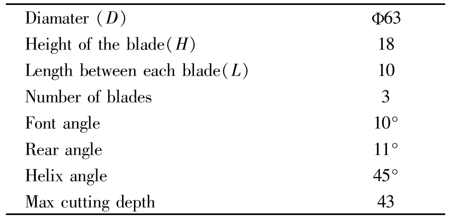
Table 1 Structure parameters of corn milling cutter

Table 2 Cutting parameters&materials
3.2 AdvantEdge FEM simulation parameter setting
When setting the blade parameters and geometry TAB of the cutter in AdvantEdge FEM software,we need to set the length,width,height,back angle of the end face cutter,side angle,front angle of the end edge,blunt radius of the side edge,radius of the edge arc,rounded cutting edge radius of the end face etc.Setting the structure parameters of corn milling cutter blade is shown in Fig.8.It is necessary to set parameters such as the number of chip slots for corn milling cutters[16-17],the number of blades on the chip slots,the spacing between blades,spiral Angle,cutter diameter and so on.Setting parameters of the inserted blade arrangement is shown in Fig.9.
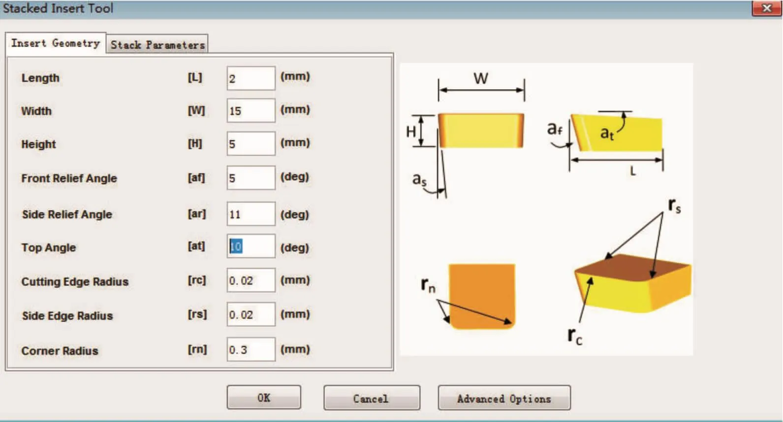
Fig.8 Setting of corn milling cutter
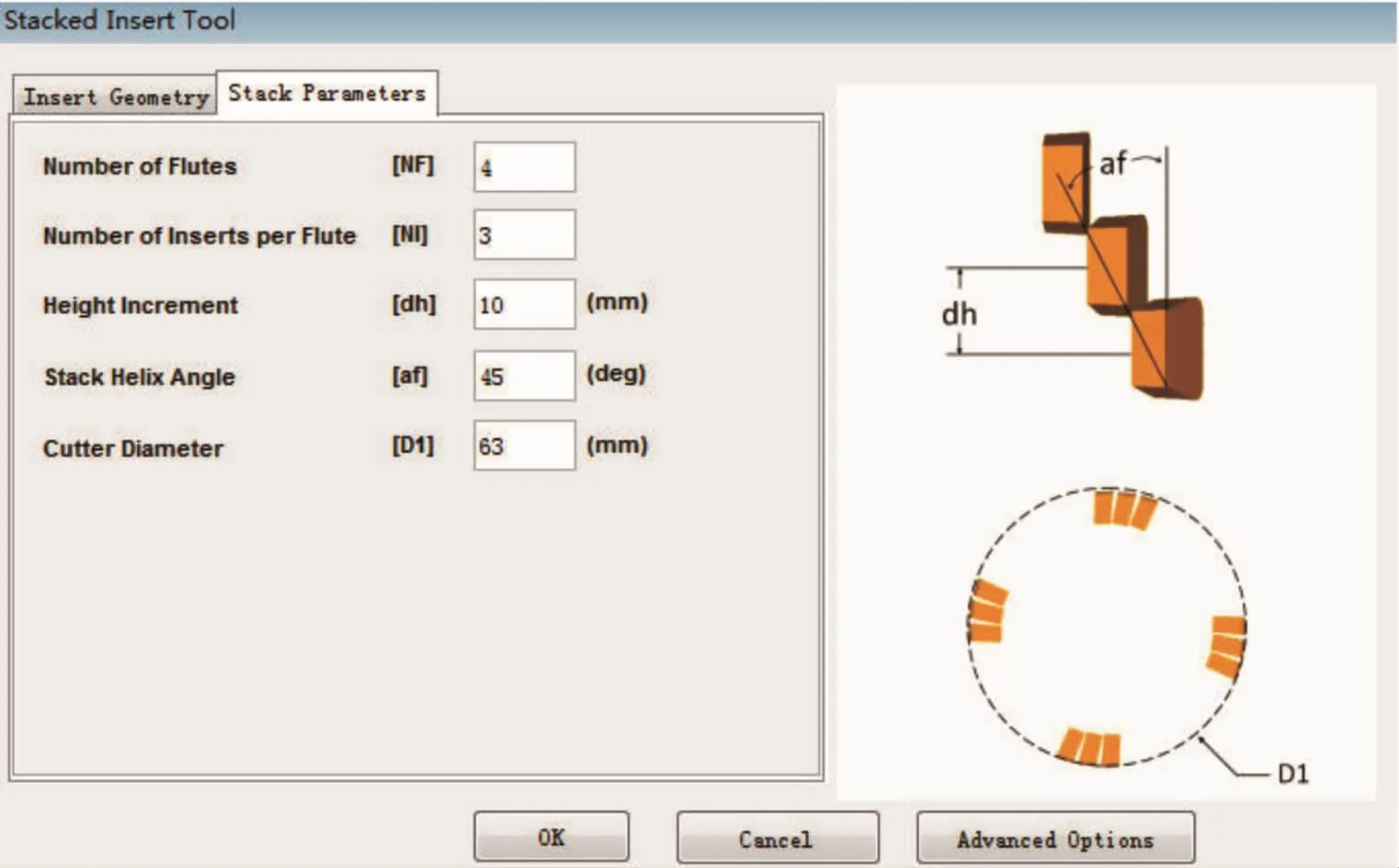
Fig.9 Corn milling cutter arrangement parametersblade structure parameters
3.3 AdvantEdge FEM meshing network
Enter the Workpiece interface and click Advanced Options.Parameters such as the maximum and minimum cell size of the grid,grid change gradient,curve precision,and node density of edges are shown in Fig.10.The divided meshing network in this section is shown in Fig.11.

Fig.10 Meshing parameters
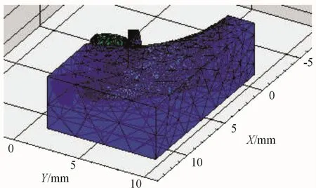
Fig.11 Meshing grid network
3.4 AdvantEdge FEM simulation result
After the above-mentioned parameters are set,the computational model is input to verify the feasibility of the model,and Fx,Fy,Fzsimulation mechanical diagrams are obtained,as is shown in Fig.12,so as the simulated cutting temperature,shown in Fig.13.

Fig.12 Simulation diagram
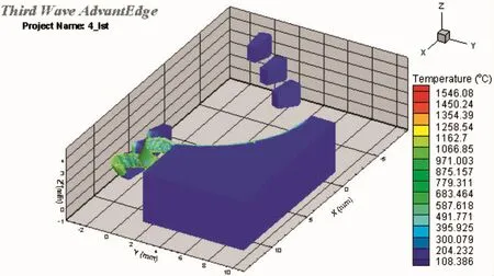
Fig.13 Simulated cutting temperature diagram
3.5 Analysis of the influence of milling force on cutting parameters
According to the FX,Fy,Fzsimulation mechanics diagram,temperature diagram,further analysis of its impact on the amount of milling can be conducted.
1)Analysis of the influence of milling force on spindle speed
The curve analysis of spindle speed and cutting force is shown in Fig.14,with continuous increase of spindle speed when corn milling cutter is milling TC4 material,both Fxand Fyin cutting force tend to decrease;but when the main speed is greater than 3 500 r/min,Fxand Fyin cutting force will increase when spindle speed is increasing.
2)Analysis of the influences of milling force on feed
When spindle speed at n=3 500 r/min and cutting depth at ap=0.35 mm,the change curve of the effect of feed amount upon cutting force is shown in Fig.15.With the feed per tooth increases,the cutting forces Fxand Fydecrease gradually.When the feed per tooth is 0.13 mm,cutting forces Fxand Fyreach the minimum value.In the actual processing,titanium alloy has more serious processing hardening layer.When the feeding amount is small,corn milling cutter blade mainly works on the surface of the hardened layer,and the cutting force is large;When the feed is greater than the thickness of the machining hardening lay-er,the blade can completely cut through the entire machining hardening surface,cutting force Fx,Fyreduce instead,with the increase of each tooth feed,the cutting layer thickness also increases,so does the cutting volume and cutting force.
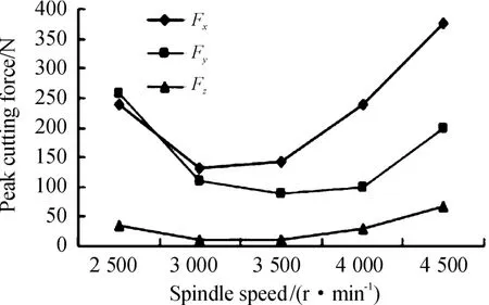
Fig.14 lnfluence of spindle speed on cutting force

Fig.15 lnfluence of feed per tooth on cutting force
3)The impact of milling force upon back cutting depth
In the experiment,the spindle speed was 3 500 r/min,and the feed per tooth was 0.15 mm/tooth.The curve of the impact of milling force upon back cutting depth can be shown in Fig 16.With the increase of the back cutting depth,the cutting forces Fxand Fyincreased significantly.When the back cutting depth is more than 0.3 mm,the cutting force in both directions of Fxand Fydecreases obviously.
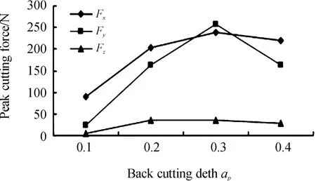
Fig.16 lnfluence of milling force on back cutting depth
4 Conclusion
In this paper,the milling force modeling of spiral corn cutter and the simulation of Advant-Edge FEM are taken as the research objects.Modeling experiments and milling force experiments were carried out,and cutting force parameters were established and simulated by the software.The simulation results are applied to the selection of cutting parameters of TC4 materials to obtain more reasonable cutting parameters,which can provide a reference for the selection of processing parameters for difficult-to-machine materials.Also ideally reduces tool wear,improves tool life,saves machining costs and achieves better economic benefits.
- 机床与液压的其它文章
- Lubricating performance of conical spindle distribution in the ball piston pump
- Mechanism analysis and control of asymmetrical digital cylinder
- Reliability analysis and calculationof the drive hydraulic system group of combined transportation
- Reliability analysis for cutterhead hydraulic drive system of remanufactured shield machine
- Application of compound buffer hydraulic cylinder in electro-hydraulic load simulator(EHLS)
- Start-up characteristics of a new electro hydrostatic actuator with an accumulator

