Flow field analysis and structure optimization of high-pressure rotary joint based on unidirectional fluid-solid coupling
Qi ZHANG,Mei-shuang HE
(School of Mechanical Engineering,Shenyang Jianzhu University,Shenyang 110168,China)
Abstract:In this paper,a high-pressure rotary joint which can be used in high-pressure condition is designed.The fluid domain is extracted from ANSYSand its structure is simulated by the Fluent.The total inlet flow rate of rotary joint is 150 L/min,and the outlet pressure is 240 MPa.The velocity and pressure distribution of the internal flow field of the pipeline are obtained by simulation,and the fluid calculation results are introduced into the solid structure for static analysis,and the deformation and equivalent stress of the solid structure are obtained.According to the simulation results,the structure of the rotary joint is optimized and simulated again.Through the comparison of the two simulation results,it shows that the pressure in the fluid domain gradually decreases with the flow direction of the fluid medium,and the velocity peak appears at the junction of the flow channel.The local stress and deformation of the joint are reduced after optimization,which has a certain reference value for the design and optimization of high-pressure rotary joint.
Key words:High-pressure rotary joint,The unidirectional fluid-solid coupling,Flow field,Static analysis,Structural optimization
1 Introduction
At present,the process of high-pressure fluid entering the rotating parts from the static pipeline often occurs in the design and application of many fluid systems.The high-pressure rotary joint is a kind of connector that allows the transmission medium to flow from the static part of the mechanical structure to the rotating part[1],which transfers the fluid flowing in the static pipeline to the rotating parts to transmit power.According to the different transmission media,the rotary joints are classified into two types:water and oil media[2].In almost industrial fields,the rotary joint is used as the connector as long as the liquid or gas medium needs to be transmitted between the fixed parts and the rotating parts[3].In different places,the structure of the rotary joint is different.However,no matter how the structure changes,it is composed of rotating parts,sealed parts and static parts.The rotating parts and the rotating cavity are connected with each other.The static parts and the static cavity are closely connected,so a complete channel must be formed between the rotating parts and the static parts[4].
Since the development of rotary joint,a number of well-known rotary joint manufacturing enterprises have been formed,such as Deublin,Kadant in the United States,Maier in Germany,Showa in Japan,and Rmkorea in South Korea.In the 1980s,the complete sets of rotary joints were introduced in China,mainlyincluding Qtype and H type,which are early products of foreign countries[5].Therefore,there have been so many simulation and testing about the rotary joint and lots of valuable experience are accumulated,which provides much help for the future development of the rotary joint.
Ma Sixuan used the Ansys WorkBench to carry out static analysis and modal analysis on the structure of the rotating joint mandrel,which can enhance the rigidity of the wear-resistant place and avoid the resonance frequency[6].Wang Yunmao used the finite element software Marc to analyze the asymmetric three cavity hydrostatic bearing in the rotary joint and solve the pressure distribution of the flow field[7].Wu Fan used the AMESim to simulate and analyze the pressure oscillation characteristics of the pipeline[8].Tang Jianguang designed a high-pressure and high-speed rotary joint.The sealing method was gap sealing,which can effectively prevent the“locking”between the mandrel and the stator[3].
Nowadays,the working pressure of rotary joint on the market is between 0 MPa and 50 MPa.In this paper,a high-pressure rotary joint is designed,which can be used in ultra-high pressure conditions.Because of the high working pressure,it is necessary to judge whether the strength of the rotary joint under the high pressure can meet the working requirements.Therefore,a unidirectional fluid-solid coupling method is used to obtain the effect of fluid on solids.The fluid domain is analyzed by using Fluent.Based on the unidirectional fluid-solid coupling,the velocity and pressure distribution in the fluid domain are analyzed.The Fluent analysis results are transmitted to the solid structure of the rotary joint for the deformation and stress distribution of the solid structure are obtained by static analysis.
2 Structure and working principle of high-pressure rotary joint
As shown in Fig.1,the rotary joint is mainly composed of mandrel 1,inlet joint flange 2,outlet joint flange 3,sealing spacer 4,shell 5,and bearing retainer 6.The inlet joint flange is evenly distributed with six inlets in the circumferential direction,and the outlet joint flange is evenly distributed with six outlets in the circumferential direction.The inlet joint flange,the bearing retainer and the shell are connected by bolts,and the two sealing spacers are fixed on the outlet joint flange by bolts.The mandrel and the outlet joint flange are fixed circumferentially.When the rotary joint works,the mandrel and the outlet joint flange rotate together.The stainless steel 17Cr16Ni12 is chosen as the material of the rotary joint except for bearings and seals,whose tensile strength limit is 1 080 MPa.
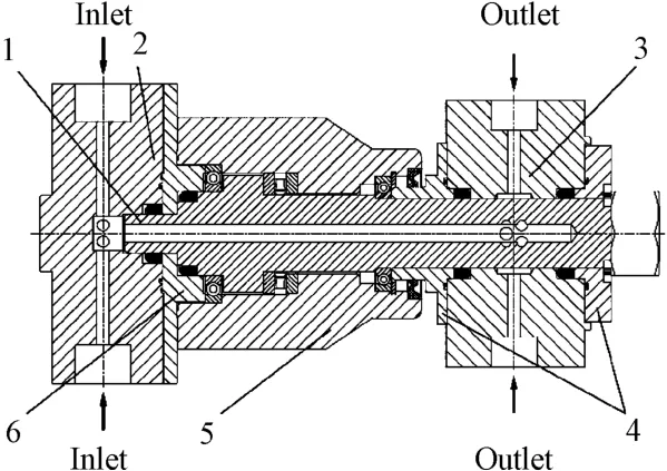
Fig.1 Structure of high-pressure rotary joint
When the high-pressure rotary joint works,the inlet joint flange,the bearing retainer and the shell all remain stationary.The mandrel,the outlet joint flange and the sealing spacer rotate together.The medium flows from the six inlets of the inlet joint flange and merges at the inlet of the mandrel.The medium flows through the mandrel and flows out from the six outlets of the outlet joint flange.The total inlet flow is 150 L/min and the outlet pressure is 240 MPa.
3 Unidirectional fluid-solid coupling analysis
3.1 Theoretical analysis
Fluid-solid coupling is a branch generated by the intersection of fluid mechanics and solid mechanics,while unidirectional fluid-solid coupling only calculates the flow field to obtain the fluid pressure acting on the surface of the structure and applies,which will as a load to the solid structure for mechanical calculation and analysis[9].In this paper,the water in the rotary joint is constant temperature water.It is assumed that the medium is continuous,uniformly distributed and incompressible.The inner diameter of the mandrel is 12 mm,then the medium velocity in the mandrel can be obtained by the following equation:

In the formula:Q is the quantity of flow(m3/s),A is the internal cross-sectional area of mandrel(m2),v is the velocity of the medium in the mandrel(m/s).
It is necessary to define Reynolds number to judge the flow state of medium in the mandrel:

In the formula:ρis the density of medium(kg/m3),d is the inner diameter of mandrel(m),μis the kinematic viscosity of the medium(kg/m·s).
The critical Reynolds number is usually 2 300 in engineering applications.When Re≤2 300,the fluid flow is laminar flow;when Re>2 300,the fluid flow is turbulent.
It follows the conservation law of physics,when the medium flows in the rotary joint.The basic conservation laws include mass conservation law,momentum conservation law and energy conservation law.For general Newtonian fluids,the conservation law is described by the following governing equation.
Mass conservation equation is represented as:

Momentum conservation equation is regarded as:
In the formula:t is the time,ffis the volume force vector,ρfis the fluid density,v′is the fluid velocity vector,τfis the shear force tensor.It can be expressed as:

In the formula:p is the fluid pressure,e is the velocity stress tensor,It can be expressed as:

The conservation equation of the solid part can be derived from Newton’s second law:

Whereρsis the solid density,σsis the Cauchy stress tensor,is the acceleration vector in solid domain.
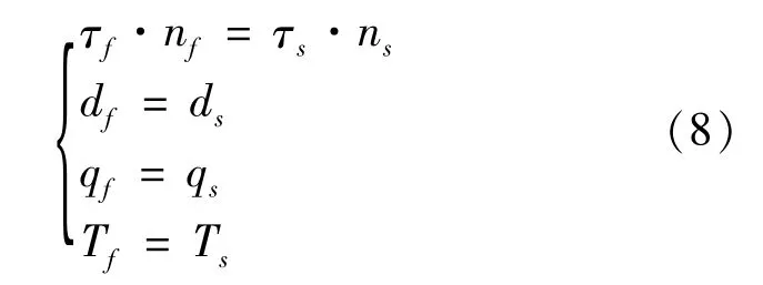
At the fluid-solid coupling interface,the stress(τ),displacement(d),heat flow(q),temperature(T)for the fluid domain should be equal or conserved,and the following four equations should be satisfied[10]:
3.2 Finite element modelling
Assuming that the deformation of the solid has no effect on the fluid and the working pressure of the rotary joint is large.The internal fluid will cause the deformation of the solid structure.In this paper,the unidirectional fluid-solid coupling is used to analyze the effect of the fluid on the solid.Fig.2 shows the solution process of unidirectional fluid-solid coupling.
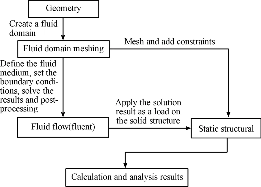
Fig.2 Solution process of unidirectional fluid-solid coupling
The 3D modeling software SolidWorks is used to draw the 3D model of the rotary joint.The shell,retainer,chamfer,threaded hole and other features do not contact with the fluid directly and will not be affected by the fluid in modeling,which are removed in order to prevent too many parts from affecting the simulation process.
The simulation analysis model is shown in Fig.3.Import the model into Ansys,extract the fluid domain of the rotary joint in Design Modeler,and name the six inlets,six outlets,and the fluid-solid coupling surface.The fluid domain model is shown in Fig.4.
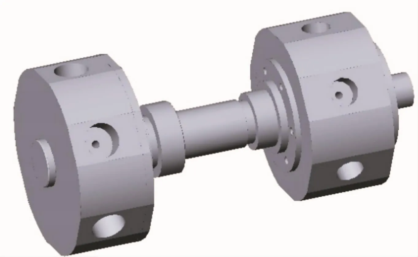
Fig.3 The 3D model
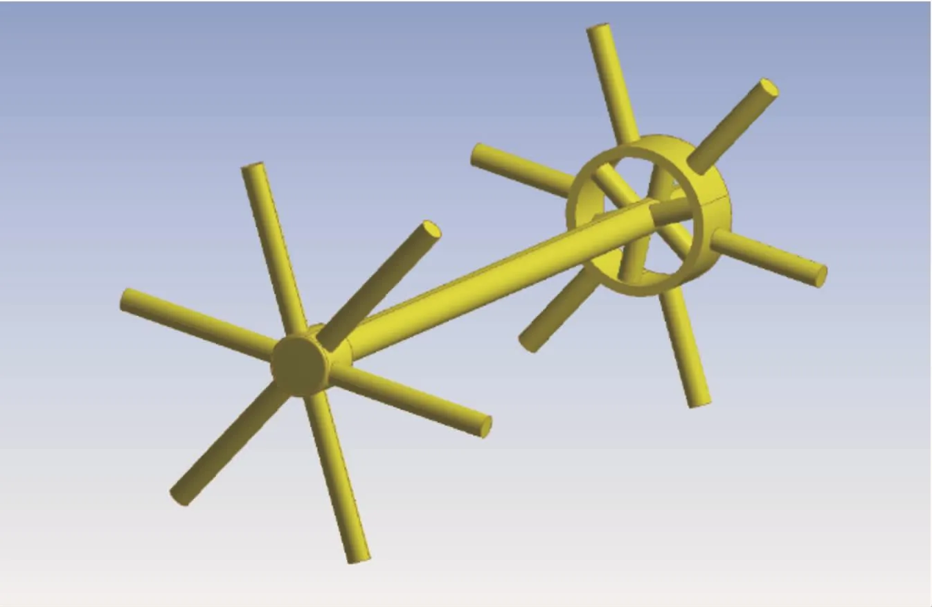
Fig.4 Fluid domain model
3.3 Simulation analysis of fluid domain
In this paper,the Mesh model in Fluid Flow(Fluent)is used to mesh the fluid domain.The mesh is tetrahedral unstructured,and the size is 1 mm.The expansion layer is set to 5 layers,and other settings are set as default.The grid is divided into 485 153 units,the skewness distribution range is 0~0.5,and the orthogonal quality is between 0.5~1.The overall quality of the grid is good.The fluid domain meshing model is shown in Fig.5.
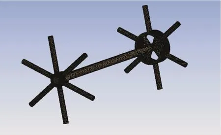
Fig.5 Mesh model of fluid domain
In Fluent,the acceleration of gravity is set at 9.81 m/s,and the k-εmodel is used for calculation during simulation.The fluid medium is defined as constant temperature water.The inlet boundary condition is the flow inlet,and the total flow is 150 L/min,which means each inlet flow is set to 25 L/min,the outlet boundary condition is the pressure outlet,and the outlet pressure is 240 MPa.Calculation residual and other parameters is set to judge whether the calculation is convergent.After initialization,the iteration steps are set to 2 000 times,and the post-processing is carried out after the results is convergent.
The velocity distribution in the fluid domain is shown in Fig.6.The maximum velocity is120.7 m/s,which is located at the entrance of the mandrel.The flow velocity in the inlet joint flange and the outlet joint flange is between 35~45 m/s.The fluid medium merges at the mandrel and the flow rate increases,so the flow velocity in the mandrel is higher than the inlet and outlet joint flange.
The pressure distribution in the fluid domain is shown in Fig.7.The pressure distribution ranges from 238 MPa to 245 MPa.The overall pressure distribution decreases with the flow direction of the fluid.The result is applied to the solid structure as a load for the next mechanical calculation[8].
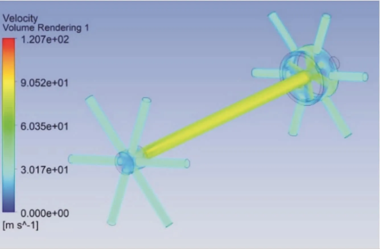
Fig.6 Velocity distribution in fluid field
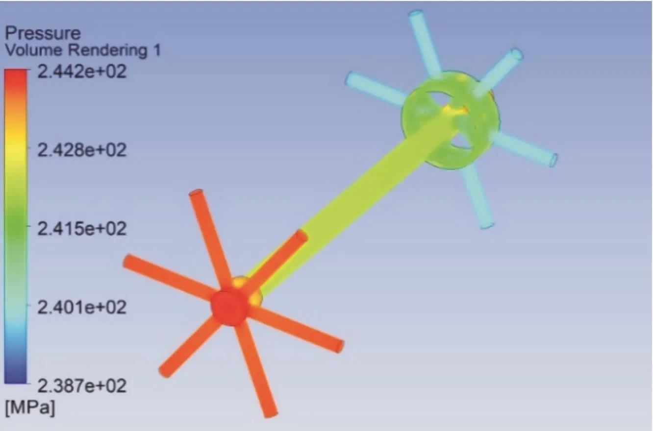
Fig.7 Pressure distribution in fluid field
3.4 Static analysis based on unidirectional fluidsolid coupling
The pressure data in the fluid domain is obtained by Fluent calculation,and the pressure data is imported into the Static Structure.The two ends of the rotary joint are constrained.The deformation of the solid structure of the rotary joint is shown in Fig.8.It can be seen that the maximum total deformation is 0.0284 mm,and its deformation gradually decreases from the inner wall of the flow channel outward,the outer deformation of the mandrel is larger than that of the inlet and outlet joint flange,so the deformation should be considered in the design of the rotary joint.It is necessary to consider leaving a suitable tolerance clearance when the mandrel and other parts are fitted.
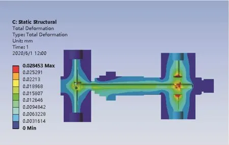
Fig.8 Deformation diagram of solid structure
The equivalent stress distribution of the solid structure is shown in Fig.9.It can be seen that the maxi-mum equivalent stress is 1 531.4 MPa at the edge of the fluid outlet for the mandrel,and the stress in other parts is between 400~600 MPa.The mandrel structure is optimized in order to prevent the structure from fatigue failure due to excessive stress.
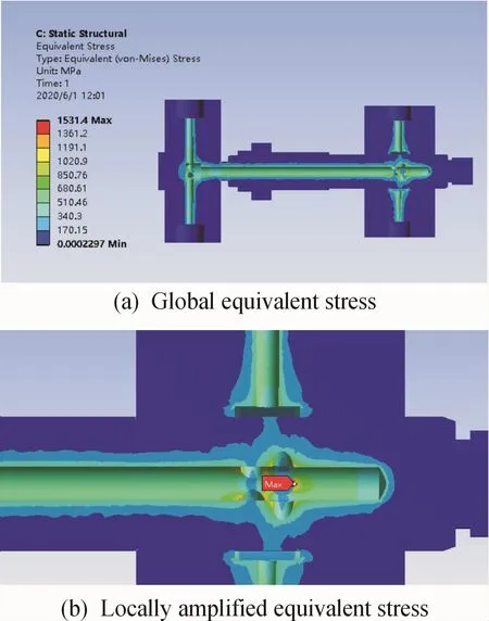
Fig.9 Equivalent stress of solid structure
4 Structural optimization and simulation of high-pressure rotary joint
4.1 Structural optimization design
According to the simulation results,it can be seen that there is a stress concentration phenomenon at the fluid outlet of the spindle.Stress concentration can cause fatigue cracks in objects,so the structure should be optimized to reduce the maximum stress and reduce the risk of stress concentration.The arrangement of the outlets on the mandrel and the number of holes have a direct effect on the magnitude of the stress.These two indexes are used as the main optimization variables to optimize.
The arrangement of outlets is changed from double row arrangement to single row arrangement for avoiding the increase of stress concentration coefficient due to the interaction between holes and the number of holes is reduced.At the same time,the contact area between the fluid and the solid structure can also be increased by increasing the inner diameter of the main shaft channel,so the equivalent stress near the outlets on the mandrel can be reduced.
In order to express the magnitude of stress concentration,the stress concentration coefficient K is defined as,

In the formula:σmaxis the maximum stress at the outlets on the mandrel,σis the nominal stress,It can be expressed as:

Where p is the pressure on the solid structure(MPa),D is the outer diameter of the mandrel(mm),t is the wall thickness of the mandrel(mm).
Fig.10 shows the structure before optimization.The inner diameter of the mandrel is 12 mm and the outer diameter of the mandrel is40 mm.Two rows of outlets are provided on the mandrel,and there are three outlet in each row.The diameter of the outlet is 8 mm.The nominal stress can be calculated as 342 MPa in the formula 10.From the result above,it can be seen that the maximum stress is 1 531.4 MPa,so the stress concentration factor can be calculated as 4.47 based on the formula 9.
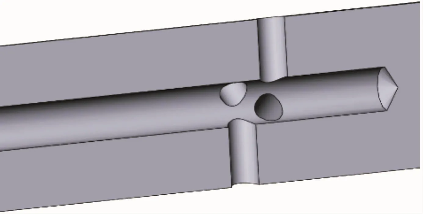
Fig.10 3D mandrel model before optimization
The optimized three-dimensional model is shown in Fig.11.The inner diameter of the mandrel has been optimally designed to be 16 mm.The outlets are set as single row,and the number of the outlets is reduced to 4.The diameter of the outlets is 10 mm.The purpose of increasing the diameter for outlets is to increase the contact area of the fluid and solid and reduce the pressure on the structure.The purpose of the decrease of holes on the mandrel is to reduce the risk of stress concentration.
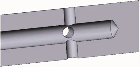
Fig.11 3D mandrel model after optimization
4.2 Simulation results and analysis
Unidirectional fluid-solid coupling simulation is carried out on the optimized structure.All simulation settings are the same as above.The fluid simulation results are shown in Figs.12 and 13,which can be seen that the maximum velocity of the flow is reduced to 74.28 m/s compared with the velocity before optimization.The pressure is distributed between 238 MPa and 244 MPa,which is similar to the outlet pressure.
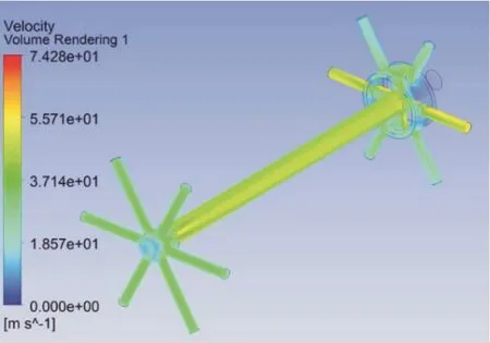
Fig.12 Velocity distribution in fluid domain after optimization
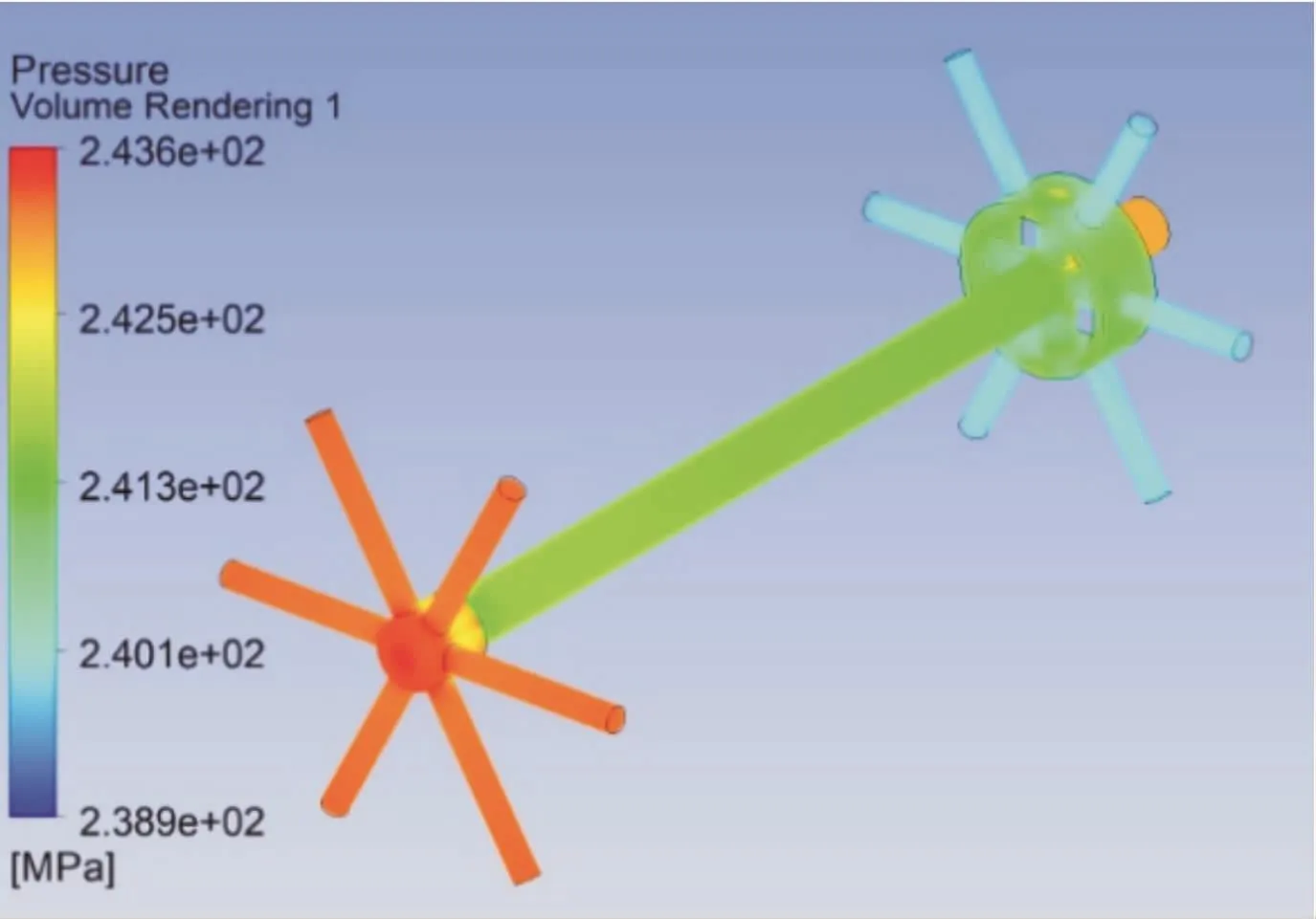
Fig.13 Pressure distribution in fluid domain after optimization
The simulation results of the solid structure are shown in Figs.14 and 15.The maximum total deformation of the rotary joint is 0.02 mm,and its deformation decreases after optimization.The maximum equivalent stress is reduced from 1 531.4 MPa to 670.39 MPa,which is located in the central cavity of the inlet joint for the flange,the inner hole of the part can be surface carburized.The nominal stress can be calculated as 400 MPa.The maximum stress is 670.39 MPa,and the stress concentration factor can be calculated as 1.68,which can be seen that stress concentration near the outlets of mandrel has been improved.
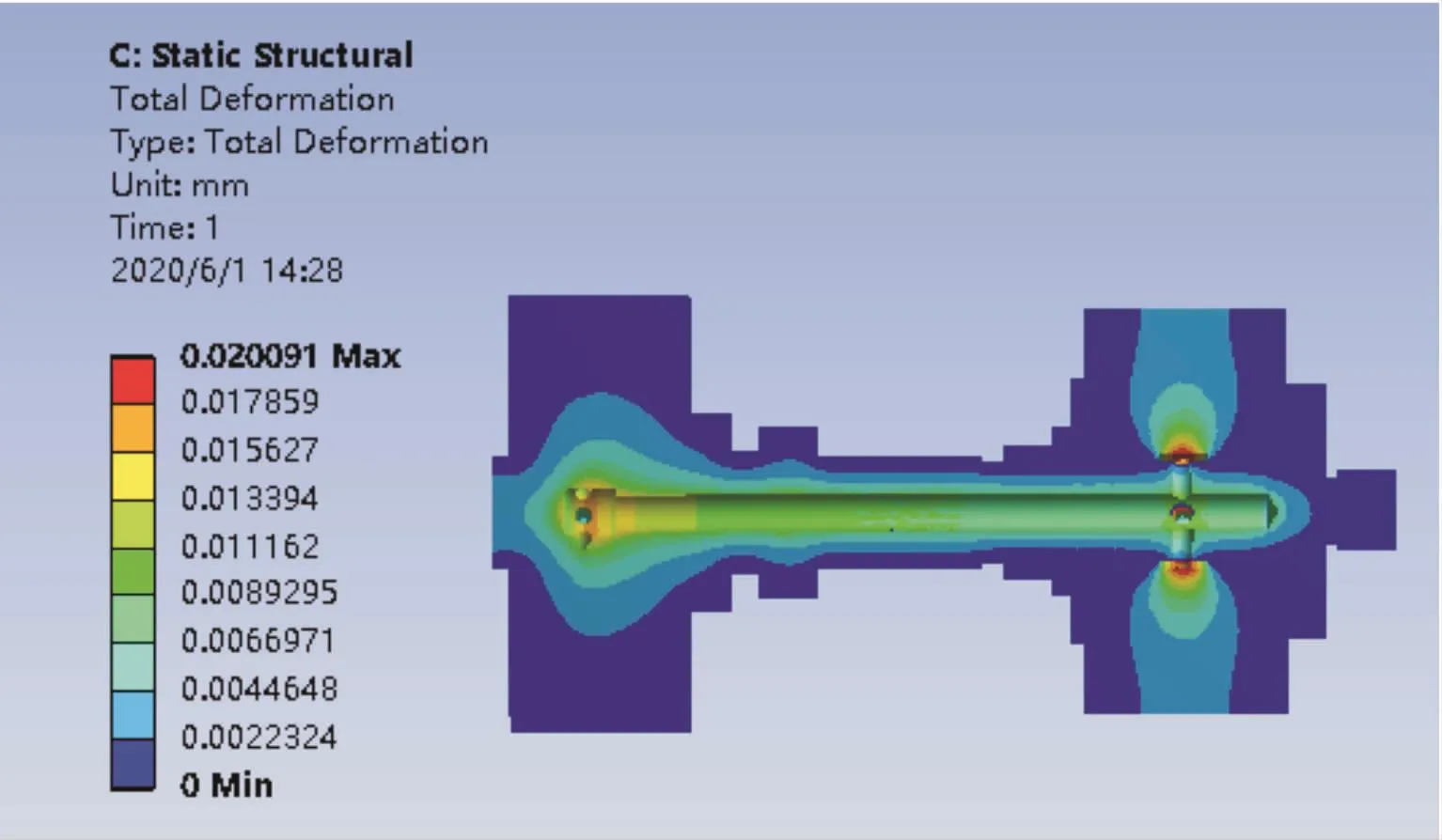
Fig.14 Deformation diagram of solid structure after optimization
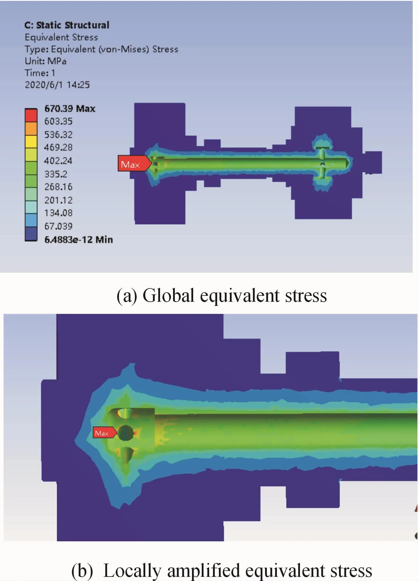
Fig.15 Equivalent stress of solid structure after optimization
5 Conclusions
In this paper,a high-pressure rotary joint is designed.The unidirectional fluid-solid coupling simulation based on Fluent is used to analyze the pressure and velocity distribution of the fluid inside the rotary joint.The fluid simulation results are imported into the solid structure as a load for static analysis.According to the solid structure deformation and stress distribution,the structure of the rotary joint is optimized.
The conclusions are as follows:
1)The pressure distribution in the rotary joint gradually decreases with the flow direction of the fluid and the overall pressure value is similar to the outlet pressure.The velocity increases abruptly at the confluence of the inlets of the mandrel due to the increased flowrate.
2)According to the simulation results,the deformation of mandrel gradually decreases from the inner wall of the flow channel outward,the outer deformation of the mandrel is larger than that of the inlet and outlet joint flange,so the deformation should be considered in the design of the rotary joint.It is necessary to consider leaving a suitable tolerance clearance,when the mandrel and other parts are fitted.
3)Six fluid outlets are set on the mandrel of the original rotary joint structure,which resulted in stress concentration and large equivalent stress value on solid structure.It is illustrated that the structure is optimized.The arrangement of outlets on the mandrel is changed from double row to single row.The number of outlets is reduced to 4 and the diameter of the outlets is increased to 10 mm.The value of equivalent stress at this location is effectively reduced from 1 531.4 MPa to 670.39 MPa and the stress concentration factor is reduced from4.47 to 1.68 based on the above optimization.The significance of optimization in this paper can immensely improve the lifetime of the rotary joint.The simulation results have some reference value for the design optimization of high-pressure rotary joint.
- 机床与液压的其它文章
- Lubricating performance of conical spindle distribution in the ball piston pump
- Mechanism analysis and control of asymmetrical digital cylinder
- Reliability analysis and calculationof the drive hydraulic system group of combined transportation
- Reliability analysis for cutterhead hydraulic drive system of remanufactured shield machine
- Application of compound buffer hydraulic cylinder in electro-hydraulic load simulator(EHLS)
- Start-up characteristics of a new electro hydrostatic actuator with an accumulator

