Numerical simulation of controlling backwardfacing step flow based on plasma actuator
Chen-guang LAI,Hang FU,Zhi-wei LING,Liang LI,Shigeru OBAYASHI
(1College of Vehicle Engineering,Chongqing University of Technology,Chongqing 400054,China)
(2 Institute of Fluid Science,Tohoku University,Sendai 980-8577 Japan)
Abstract:In order to explore the effect of surface of dielectric barrier discharge(SDBD)plasma on flow separation of backward-facing step.We used the proposed plasma effect on fluid numerical simulation method by Suzen.Andapplied Fluent software to calculate the electric field distribution and charge density distribution equation.By compared the results with the existing experimental data and verify the accuracy of the simulation method.On this basis,plasma excitation was applied to the front of the step to observe its control effect on the flow separation of the back step.The simulation results show that the plasma aerodynamic excitation can significantly reduce the backward-facing step flow’s reattachement distance.When the incoming flow’s wind speed is 1 m/s,the reattachment length can be reduced by 53.92%.When the incoming flow’s wind speed increases gradually,the effect of plasma aerodynamic excitation control gradually weakens.When the excitation intensity is increased,the control effect is enhanced.
Key words:Plasma,Backward-facing step,Reattachment length,Flow separation
1 Introduction
In recent years,active flow control technology has become an increasingly attractive research topic in the field of aerodynamics,especially,the active flow control of plasma has attracted the attention of researchers for its simple structure,low energy consumption,fast response and other advantages[1].Plasma is the fourth state of matter other than concrete,liquid and gas,which contains a large number of ions paired with electrons,and its motion shows significant collective behavior under the control of electromagnetic field force[2].At the present,flow control by surface dielectric barrier discharge(SDBD)plasma actuator is the most commonly used method,because compared with DC corona discharge,the plasma generated is more uniform.The control effect is better[3].The plasma actuator structure is shown in Fig.1.The two electrodes are separated by an insulating medium layer and arranged asymmetrically.The exposed and implanted electrode are connected to the power supply respectively.The air around the exposed electrode will be ionized when a high voltage is applied to it.This produced the plasma shown in Fig.1.The plasma accelerates under the action of electric field forces and collides with fluid moleculesto transfer kinetic energy,thus in-ducing flow[4].Some researchers have usedplasma to inhibit airfoil flow separation,thereby reducing airfoil drag and increasing lift[5-6].At the same time,the SDBD plasma has also been applied in shock wave control[7],turbine compressor stability and efficiency enhancement[8],slender vertebral body drag reduction[9],noise reduction and muffling[10].However,the mechanism of plasma flow control has not been definitively concluded.Roupassov et al.[11]believed that the energy coupling mechanism was related to the excitation power used.For AC discharge,the momentum transmission from the electric field to gas to induce fluid flow was the primary influencing mechanism,In contrast,for nanosecond pulse discharge,the energy transmission to induce fluid flow was the primary influencing mechanism,which was recognized generally.
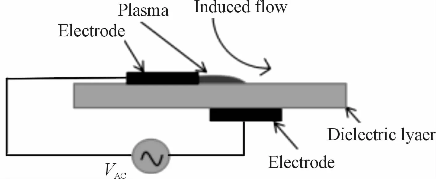
Fig.1 SDBD actuator structure
The flow on the backward-facing step represents a kind of flow around the bluntbody[12].Its geometric model is shown in Fig.2,there will be flow separation and reattachment at the back of the step.The flow separation has many adverse effects,such as increased drag and noise.Therefore,controlling the size of the separation zone and reducing the reattachment length is the focus of the research.Zheng Chaorong et al.[13]conducted air actuation at the bottom of the back step in the direction of the step to control the length of fluid reattachment,and concluded that the greater the suction intensity,the better the control effect.Wang Jingyu et al.[14]used plasma to control the reattachment length of fluid in the separation area behind the step.Under the inflow condition of 5 m/s,it was concluded that the position of the reattachment length moved forward by 45.27%,and the better control effect was increased by actuation intensity.Boom Y J et al.[15]applied plasma actuation on the upper part of the back step which effectively inhibited fluid flow separation under the premise of controlling total pressure loss and flow uniformity.
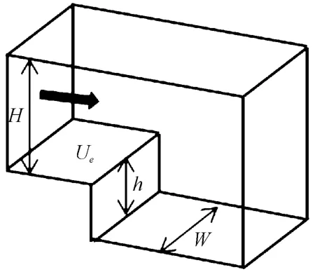
Fig.2 Geometric model of rear step
In this paper,based on algorithm proposed by Suzen[4].The potential and charge density distribution equations were solved by user defined scalar(UDS)in Fluent,and the boundary conditions were given by user defined function(UDF).The plasma volume force is added to the fluid dynamics equation in thein the form of amomentum source term.The adjustable parameters in the equation are corrected by verifying with the experimental data in the literature[16].Finally,to explore plasma’s influence on the control effect of backward-facing step flow under different incoming flow velocity and actuation voltage.This paper’s results have some guiding significance for the application of plasma flow field active flow control to reduce drag and noise.
2 Geometry and simulation method
2.1 Plasma model and simulation method
The plasma actuator we selected is shown in Fig.1.To obtain the effect of plasma on fluid,the body force under plasma action need to be solved.Under the assumption of ignoring the electro magnetic force,the force per unit volume can be expressed as:

Whereρcis charge density,and theE→ is electric field intensity.Ignoring the unsteadiness of magnetic field change,Maxwell’s equation can be expressed as▽ ×≈0,The intensity of the electric field can be calculated from the scalar potential gradient:

By Gauss’s law:

Whereεis dielectric constant.
Since gas particles are separated by aweak current,the total electric potential can be considered to be composed of two parts,they are generating by the external electric field.Net charge density in the plasma.So,the total electric potential can be expressed as:

Therefore,two independent equations from two potentials can be written as:

WhereλDDebye length,for the detailed derivation of equation 6,please refer to[4].Theρcandφcan be obtained by solving equation(5)and(6),the plasma body force can be obtained from equation(1).
Fig.3 shows the boundary conditions and the simulation domain of theelectric potential equation.The potential at the buried electrode is equal to0,the normal gradient of the potential at the outer boundary is equal to 0.And the dielectric constants of the fluid domain and the solid domain are 1.0 and 2.7 respectively,applied sinusoidal ac voltage at exposed electrode:

Whereφmaxis potential amplitude,theωis actuation frequency.
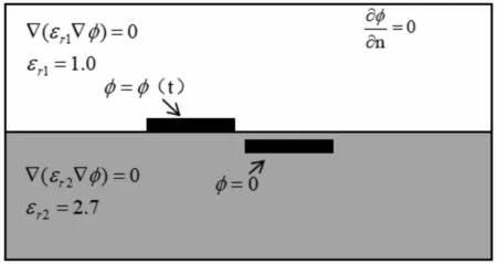
Fig.3 Boundary conditions and simulation domain of equation(5)
Fig.4 shows the boundary conditions and the simulation domain of charge density equation.The charge density at the outer boundary is equal to 0,and the normal gradient of charge density on the other walls is equal to 0 except the wall above the buried electrode.The charge density on the wall above the buried electrode can be expressed as,

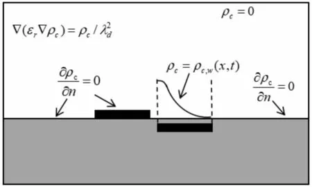
Fig.4 Boundary conditions and simulation domain of equation(6)
The plasma numerical simulation mesh strategy is shown in Fig.5.Using structured grid,and enhanced the mesh density around the electrodes.
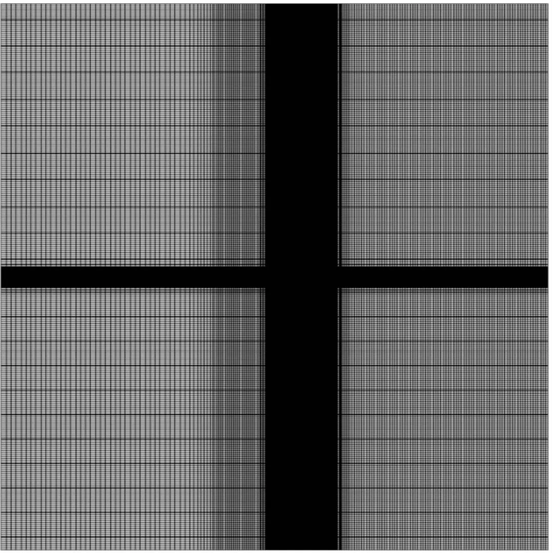
Fig.5 Mesh strategy
In order to compare with the experimental results of Karthik Ramakumar et al.[16],to verify the accuracy of the simulation method,the actuation parameters are the same as the experimental settings.The actuation voltage amplitude is 5 kV,and the actuation frequency is 4.5 kV.The turbulence model was S-A(Spalart-Allmaras)turbulence model[17].
2.2 Backward-facing step model and simulation method
The geometric model of the backwardfacing step adopted in this paper is shown in Fig.2,In order to facilitate the comparison with experimental results,where the step height is25 mm.The simulation domain is shown in Fig.6.The plasma actuator is set at the front of the step,the origin is at the far right of the exposed electrode.To fully develop the flow,the step is 5 h away from the inlet,15 h away from the outlet,and 10 h away from the upper wall.
The strategy of the mesh also adopts structured mesh(see Fig.7).The mesh is encrypted around the step and at the position of the plasma of applied.Themesh quality is verified by mesh independence.The total number of grids is 55 000.
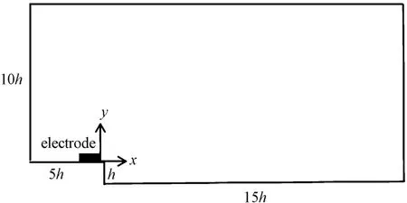
Fig.6 Backward-facing step simulation domain

Fig.7 Mesh strategy
The setting of boundary conditions is shown in Table.1.The inlet is the velocity inlet.The outlet is the pressure outlet,the upper wall is the symmetric plane,and the lower wall is the non-sliding wall.The shear stress transport SST turbulence model based on the RANSmethod is used in the simulation.The model has good accuracy and stability in simulating the flow in the near-wall area with low Reynolds number.

Table 1 Boundary condition
3 Results and discussion
3.1 Theresultsof plasma numerical simulation in static air
The numerical simulation results of potential and charge density distribution are shown in Fig.8 and Fig.9(normalized).It can be seen from the potential distribution that there is a large gradient change in the potential between the two electrodes.Indicating that the electric field intensity here is large and the plasma concentration in this area is large.From the charge density distribution,it can be observed that the charge density reaches its maximum in the upper left corner of the buried electrode and gradually decreases along the downstream direction of the electrode.The plasma generation area is mainly in the downstream of the exposed electrode and above the buried electrode.
Fig.10 is the velocity contour of plasma induced fluid flow in the static air.From the figure,it can be observed that the plasma exerts a jet near the wall,and the maximum velocity of the jet is 1 m/s,which is consistent with the experimental results[16].The velocity streamline of experiment and simulation(see Fig.11)is also similar.This is shown the accuracy of the numerical simulation method.
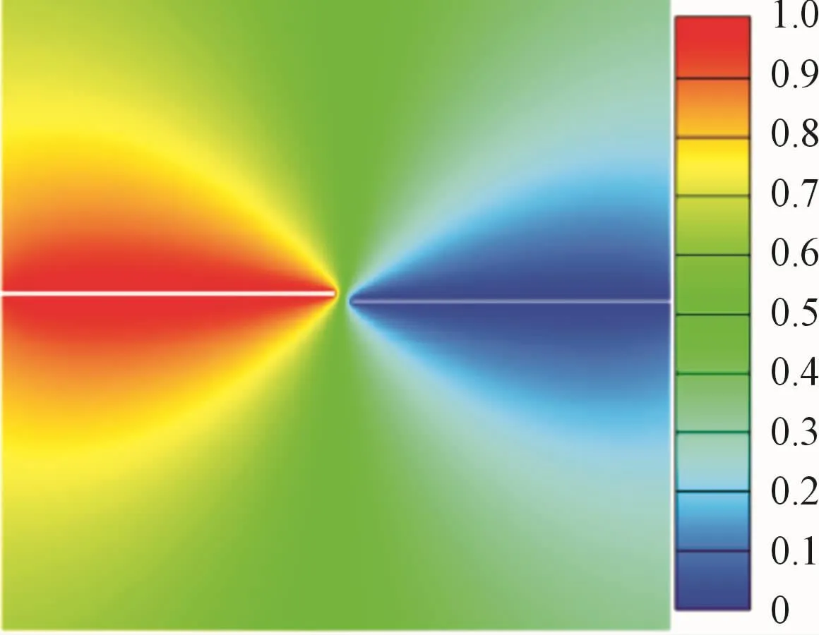
Fig.8 Potential distribution

Fig.9 Charge density distribution

Fig.10 The velocity contour

Fig.11 Velocity streamline
3.2 The results of backward-facing step numerical simulation
In this paper,5 m/s free incoming flow wind speed is adopted as the primary working condition,and the velocity contour and streamline are obtained through simulation,as shown in the Fig.12,each flow pattern of BFScan be clearly observed,and it can be divided into three parts along the flow direction:separation,reattachment and redevelopment zones.It can also be divided into three parts along the vertically direction:corner vortex,surround and main core area.The experiments of Saric et al.proved this flow state[18].

Fig.12 Velocity contour and streamline
Besides,the lower wall’s shear force downstream of the backward-facing step along the x direction is also obtained,as shown in Fig.13.Its clearly observed that the very first,a part of positive value appears,which corresponds to the corner vortex region in Fig.13.A negative value corresponds to the surrounding region in Fig.13,and finally returns to the positive value,which corresponds to the reattachment region and the redevelopment region in Fig.13.Therefore,fluid’s reattachment position can be determined by changing the direction of the wall shear force.The reattachment point is x/h=5.795 8 at 5 m/s condition,compared with the measurement results of the split film probe by Uruba et al.[12],the error is3%,meet the accuracy requirement.
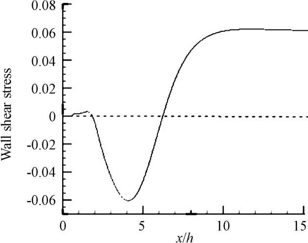
Fig.13 Wall shear stress(5 m/s)
3.3 The results of plasma control model
3.3.1 Influence of incoming flow velocity on plasma control
To observe the influence of incoming flow velocity on the step flow after plasma control,and keep the actuation parameters of the plasma unchanged,which the voltage amplitude is 18 kV.The actuation frequency is 30 kHz[19].In addition to the reference condition of 5 m/s considered above,the effects of plasma under different incoming flow velocity of 1 m/s,2 m/s,4 m/s and 10 m/s are also considered.After iterative calculation,the x-direction shear force diagram of the rear underside of the step in each working condition under the action of plasma or not was obtained,as shown in the Fig.14.Its clearly observed that under control of plasma in various flow velocity all have acertain effect,and make the reattachment position forward.Under the inflow velocity of 1 m/s,the influence on the back step flow separation zone is the largest.The forward distance of the reattachment point is obvious.However,the local shear force is in-creased,which means that the local energy loss is increased.At the inflow velocity of 10 m/s,the influence on the back step’s flow field is small,and the forward movement distance of the attachment point is small.It also means that the plasma has a good control effect at the low flow velocity.The control effect is significantly weakened with the increase of the flow velocity.Fig.15 is shown the velocity contour before and after plasma actuation at 2 m/s.
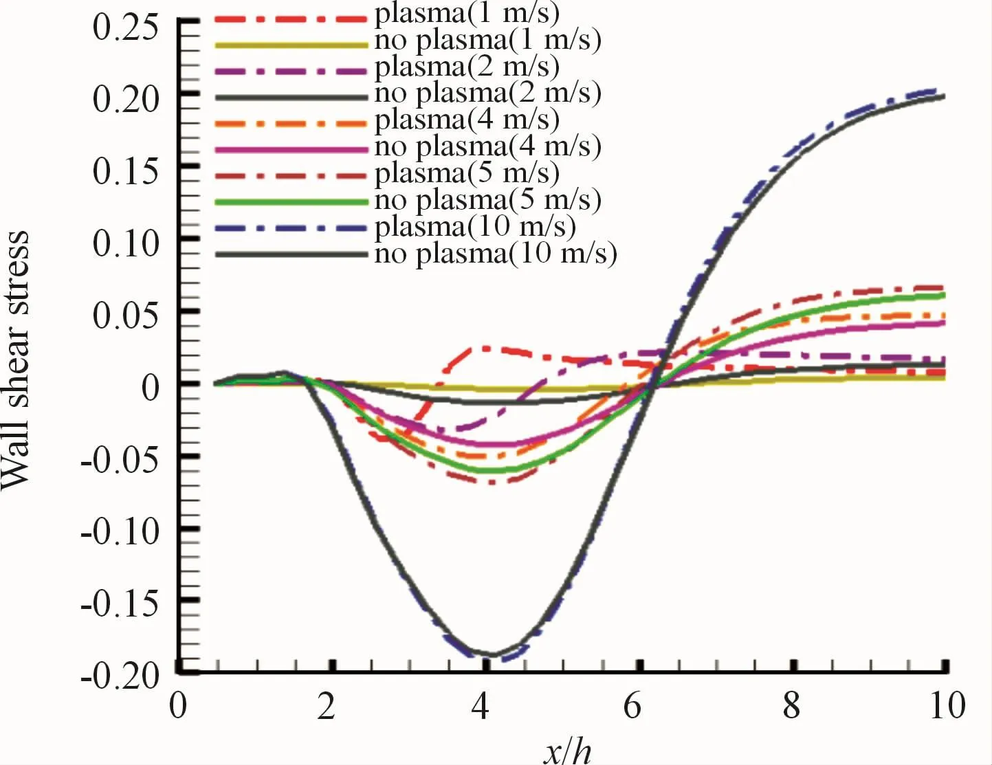
Fig.14 Wall shear stress

Fig.15 Velocity contour(2 m/s)
As we can see from the velocity contour in Fig.15,the model with plasma actuation formed a jet stream at the downstream near the exposed electrode wall,which induced the fluid to accelerate.The increase of velocity near the wall results in the increase of momentum in the boundary layer,which improves the ability of the boundary layer to resist the adverse pressure gradient,and delays the separation of the boundary layer.Ultimately,it leads to the narrowing of the separation zone and the forward movement of the fluid reattachment position.Velocity distribution along withy direction 5 mm downstream of the electrode(see Fig.16).In the absence of plasma,the boundary layer’s velocity increases gradually from the wall to the mainstream.In the presence of plasma,the velocity in the boundary layer experiences a period of sudden increase and then gradually recovers to reach the flow velocity.The velocity distribution under plasma actuation is fuller in the boundary layer,which is conducive to the delay of boundary layer separation.
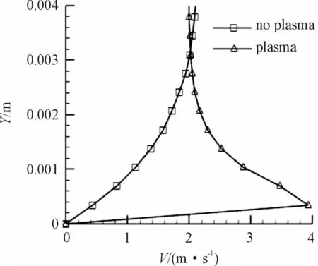
Fig.16 The velocity distribution along y direction is 5 mm downstream of the electrode
Table 2 is shown the effect of plasma actuation.We can see the plasma at low flow velocity control effect is very good from the Table.2,the reattachment position ante displacement 3.412 6 h,the percentage of reduction is 53.92%.The control effect decreases with the increase of incoming flow velocity.In order to improve the control effect of plasma,actuation intensity must be increased.
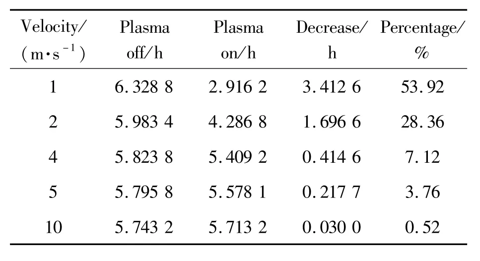
Table 2 Plasma control effects under different incoming flow velocities
3.3.2 Influence of actuation voltage on plasma control
Due to the actuation frequency effects on the maximum average speed induced by plasma is weaker[19].Therefore,we only considering the influence of actuation voltage on plasma controlled BFS flow.Keeping the velocity of 5 m/s unchanged,and the ac-tuation voltage by 18 kV,up to 20,22,24 kV,The above methods are used for numerical simulation,get the results as shown in Table 3.

Table 3 Plasma control effects under different actuation voltage
As we can see from Table 3,the plasma control effect is improved with the increase of actuation voltage under the same inflow velocity.Compared with the reference condition,the reattachment position moved forward by 0.510 5 h.The separation zone length decreases by 8.81%,when the excitation voltage is increased to 24 kV.Fig.17 shows the velocity distribution along y-direction at 5 mm downstream of the electrode under different actuation voltage.It can be seen from the Fig.17 that the plasma’s ability to induce fluid acceleration increases with the increase of actuation voltage.This makes the velocity distribution within the boundary layer is fuller,thus enhancing the boundary layer’s ability to resist the adverse pressure gradient.The boundary layer delays separation.The separation zone of the back step flow decreases,and then the attachment point position moves forward.

Fig.17 The velocity distribution along y direction is 5mm downstream of the electrode
4 Conclusions
By applying plasma actuation to control back step flow,the following conclusions can be drawn,
(1)The plasma active flow control can obviously move forward backward step flow reattachment position,when the incoming flow velocity is relatively low.The control effect decreases with the increase of incoming flow velocity.
(2)Increasing the plasma actuation voltage can significantly improve its control ability,when the incoming flow velocity is constant.
- 机床与液压的其它文章
- Lubricating performance of conical spindle distribution in the ball piston pump
- Mechanism analysis and control of asymmetrical digital cylinder
- Reliability analysis and calculationof the drive hydraulic system group of combined transportation
- Reliability analysis for cutterhead hydraulic drive system of remanufactured shield machine
- Application of compound buffer hydraulic cylinder in electro-hydraulic load simulator(EHLS)
- Start-up characteristics of a new electro hydrostatic actuator with an accumulator

