Transmission analysis and simulation of precision ball planetary reducing mechanisms
Wei WANG,Xi HUAN,Dong-qiang GAO
(1 Department of Aeronautical Engineering,Shaanxi Polytechnic Institute,Xianyang 71200,China)
(2 College of Mechanical&Electrical Engineering,Shaanxi University of Science&Technology,Xi’an 710021,China)
Abstract:The precision ball planetary reducing mechanism is a type of high-efficiency and energy-saving cycloidal transmission mechanism.Here,a two-stage cycloidal ball planetary transmission mechanism(CBPTM)is designed,which employed the deceleration balls as the transmission mediumand achieved the gapless meshing transmission in a circulating raceway formed by the epicycloid groove and the hypocycloid groove.The transmission principle of the planetary reducing mechanism is analyzed,and the transmission ratios of different types of the CBPTM are calculated.Based on the platform of automatic dynamic simulation software ADAMS,the kinematics simulation of the two-stage CBPTM is conducted,meanwhile,the angular velocity,angular acceleration curves of the planetary disc and the cycloidal disc during the movement process have been obtained.The smoothness of motion and transmission rationality of the deceleration mechanism have been verified and analyzed,which provides the basis for the structural optimization and transmission ratio design for the two-stage cycloidal ball planetary reducing transmission.
Key words:Cycloidal ball planetary mechanism,Transmission analysis,ADAMS,Motion simulation
The cycloidal ball planetary transmission mechanism(CBPTM)is a new gapless meshing transmission system that employs active balls as an intermediary body to transmit movement and power[1-3].The precision mechanism shows the advantages of no backlash transmission,high meshing efficiency,high coincidence degree and large transmission ratio for applications in robot joint transmission,servo device,precision indexing device,micro transmission mechanism,etc.[4-6],which has received the promising attention of domestic and foreign researchers.
The planetary reducing mechanism shows an important effect on the CBPTM system.In the actual conditions,a reasonable transmission ratio can be achieved by adjusting the combination of hypocycloid disk and epicycloid disk.And hence the transmission analysis is a fundamental work for the evaluation of the structural design[7].
In this paper,a two-stage cycloidal ball reducing mechanism was designed,and then the transmission characteristics for the combination of different cycloid grooves were analyzed.After completing the design of the CBPTM,the movement of the deceleration meshing transmission,and the angular velocity curves and angular acceleration curves of the deceleration mechanism were simulated and analyzed by the kinematic analysis software ADAMS,which provide a reference for the optimization design and transmission analyses of mechanism.
1 Structural analysis of the CBPTM
The CBPTM was a type of high-efficiency and energy-saving precision cycloidal ball transmission that was a special transmission form for small tooth number difference planetary transmission.In generally,the CBPTM employed the balls as the transmission medium,and performed a gapless meshing movement in a circulating raceway composed of a hypocycloid groove and an epicycloid groove,achieving the power transmission and speed conversion between the coaxial[8].
Fig.1 shows the schematic illustrations of a twostage CBPTM,and which consists of an eccentric input shaft,double deceleration meshing pairs with opposite cycloid grooves,an equal-velocity meshing pair with ring grooves.Note that the first-stage deceleration system comprised a center disk with a continuous epicycloid groove(Fig.1(c)),a planetary eccentric disk with a hypocycloid groove on the end surface(Fig.1(d)).And a certain number of deceleration balls were arranged between the cycloid grooves for deceleration meshing transmission.Similarly,the second-stage deceleration system consisted of a planetary eccentric disk with a hypocycloid groove,an output disk with an epicycloid groove(Fig.1(f))and some deceleration balls.In addition,to ensure the stable movement of the balls,a bearing retainer can be added to ensure that the circumferential distance between the balls was evenly separated.
The equal-velocity transmission mechanism was composed of two planetary disks(ring-groove face to face)that installed on eccentric portion of the input shaft.The phase difference between the eccentric portion was 180°to balance the inertia load[9].The equal-velocity balls were arranged in the axially coincident position of the ring grooves,and the balls engaged with the ring raceways formed by ring-grooves(Fig.1(e)).
As the eccentric input shaft rotated at a constant angular velocity(ω1),the first eccentric portion of the shaft drove the left planetary disk to revolve around its eccentric axis.Owing to the center disk was fixed,the force between the center disk and the balls drove the planetary disk to rotate around its axis at a lower angular velocity(ω2),achieving the first-stage deceleration transmission.Furthermore,the angular velocity(ω2)of the left planetary disk was output to the right planetary disk at the equal velocity ratio by the equalvelocity ring-groove transmission mechanism.Moreover,the second eccentric portion of the input shaft drove the output disk to revolve around its eccentric axis,and the output disk and the balls meshed by the cooperative force.Finally,the force drove the output disk to rotate at a lower angular velocity(ω3),achieving the second-stage deceleration transmission.
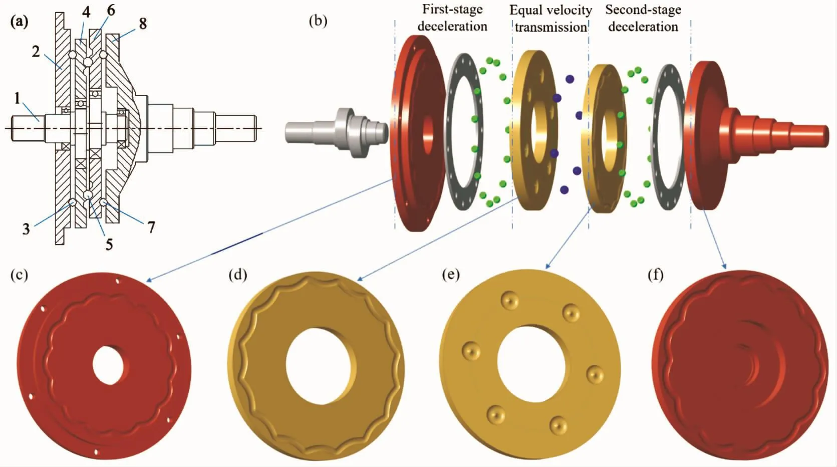
Fig.1 Structural characteristics of a two-stage CBPTM:(a)schematic illustrations,(b)structural model,(c)center disk with an epicycloid groove,(d)planetary eccentric disk with a hypocycloid groove,(e)planetary disk with ring-groove,(f)output disk with an epicycloid groove
2 Transmission principles of the different CBPTMs
According to the structural principles of the CBPTM,the different structural types of single-stage transmission can be designed by combining the different types of meshing cycloidal grooves,such as Type-Ⅰ,type-Ⅱ,type-Ⅲ,type-Ⅳ,as described in Fig.2.
For the structural diagram of type-Ⅰ(Fig.2(a)),an epicycloid groove was designed on the end surface of afixed disk(i.e.center disk or epicycloid disk).A hypocycloid groove was designed on one end surface of the planetary disk that was installed on the eccentric portion of the input shaft.The balls meshed between the epicycloid groove and the hypocycloid groove for deceleration transmission.
In addition,the ring-groove was designed on the other end face of the planetary disk and on the end surface of output disk(or output shaft).The balls meshed between the ring raceways that formed by both sides ring-grooves.After deceleration transmission,the rotation speed of the planetary disk was output by output shaft at the equal velocity ratio.The transmission direction of the input shaft and the output shaft was identical at such structural type.
As compared with type-Ⅰ,type-Ⅱ showed a similar structural transmission method,the difference was the configuration of the cycloid disks(Fig.2(b)).The center disk of the type-Ⅱwas designed to a hypocycloid groove on the end surface,and the planetary disk was designed to an epicycloid groove.The transmission direction of the input shaft and the output shaft was opposite.
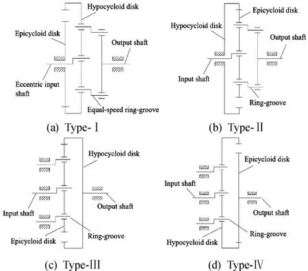
Fig.2 Structural types of the single-stage CBPTM
In contrast,the type-Ⅲ and the type-Ⅳ showed different structural characteristics.The input disk was a planetary equal-velocity disk with the ring-groove and the cycloid groove on both end surfaces respectively.The output disk was designed to a cycloid disk for deceleration transmission.The difference was that the input disk of type-Ⅲ was an epicycloid disk,and the input disk of type-Ⅳwas a hypocycloid disk.Meanwhile,the transmission direction of type-Ⅲ was the same,and the transmission direction of type-Ⅳ was opposite.
The schematic diagram of the two-stage cycloidal ball transmission in Fig.1 isa parallel structure composed of two first-stage CBPTMs.According to the different combination types,the two-stage CBPTM presents four types of different configurations,as shown in Fig.3,where the first-stage deceleration transmission can be type-Ⅰortype-Ⅱ,and the second-stage deceleration transmission can be type-Ⅲ or type-Ⅳ.
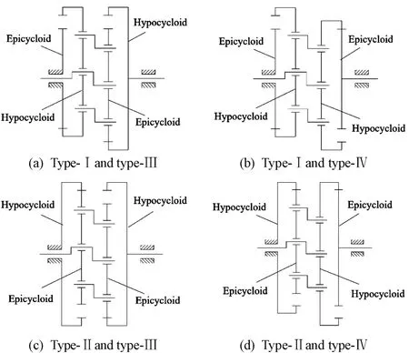
Fig.3 Structural types of the two-stage CBPTM combined with different types
3 Analysis of transmission ratio of the CBPTM
3.1 Transmission ratio of the one-stage CBPTM
The cycloidal ball transmission belonged to the KH-V transmission mechanism.During the meshing transmission,the planetary disk rotated around its own axis(i.e.eccentric axis of the input shaft)and the center axis of the input shaft,and hence the CBPTM corresponded to an epicyclic gear train.The transmission ratio(i)can be calculated by the mechanism conversion method,adding a common angular velocity to the entire epicyclic gear train,and converting it into a hypothetical fixed-axis gear train[9].As a result,the transmission ratio of the CBPTM can be calculated by calculating the transmission ratio of the conversion gear train.
In Fig.2(a),the epicycloid teeth of the center disk(K)are defined as Z1,and the angular velocity is defined asω1.In addition,the hypocycloid teeth of the planetary disk are Z2(Z2-Z1=2),and the corresponding angular velocity isω2.A hypothesis was proposed,namely the angular velocity of the planet carrier(H)was assumed to beωH.By adding a global angular velocity(-ωH)to the entire mechanism,the epicyclic gear train was converted into a fixed-axis gear train.Taking the planet carrier(H)as a relative reference,the relative angular velocity(ωH)of each member was as follows.
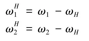
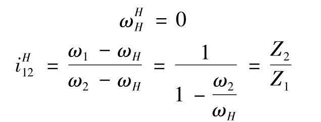
Therefore,the iⅠof the type-ⅠCBPTM was derived.

Note that the i was equal to half the number of the hypocycloid teeth.
In Fig.2(b),for the type-ⅡCBPTM,the calculation of the iⅡis similar to the type-Ⅰ CBPTM.The difference was that the center disk was a hypocycloid groove(hypocycloid teeth is Z1),and the planetary disk was an epicycloid groove(epicycloid teeth is Z2,and Z1-Z2=2).
The iⅡof the type-Ⅱ CBPTM was obtained as follows.

Note that the iⅡwas equal to half the number of the epicycloid teeth,and the transmission direction of the input shaft and the output disk was opposite.
Similarly,the i of the type-Ⅲ and the type-Ⅳ CBPTMs can be derived as follows.
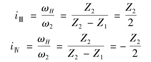
In a word,the transmission ratios of the type-Ⅰand the type-Ⅲ were the same,and the number of deceleration balls were nb=2i-1.In addition,the transmission ratios of the type-Ⅱ and the type-Ⅳ were the same,and the number of deceleration balls were nb=1-2i=|2i|-1.
3.2 Transmission ratio of the two-stage CBPTM
As shown in Fig.1(a),the two-stage CBPTM is a typical epicyclic gear train,where the teeth of the center disk are defined as Z1,the angular velocity is defined asω1;the teeth of the left planetary disk are defined as Z2,the angular velocity is defined asω2;the teeth of the right planetary disk are defined as Z3,the angular velocity is defined asω3;the teeth of the output disk are defined as Z4,the angular velocity is defined asω4.The angular velocity of the hypothetical planet carrier(H)is assumed to beωH.By adding a global angular velocity(-ωH)to the mechanism,the epicyclic gear train was converted into the fixed-axis gear train.Taking the planet carrier(H)as a relative reference,the relative angular velocity(ωH)of each member was as follows.
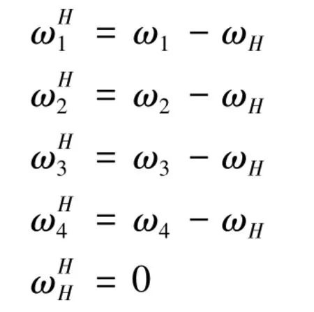
The relative transmission ratio of the center disk and the output disk can be obtained.

The transmission ratio(I)of the two-stage CBPTM can be deduced as follows,

All in all,for different configurations in Fig.3,when the epicycloid teeth and the hypocycloid teeth are known,the I of the two-stage CBPTM can be calculated.To analyze the I of four types in Figure 3,a series of parameters can be given as follows:
(a)Group 1:Z1=15,Z2=17,nb1=16;Z3=14,Z4=16,nb2=15;
(b)Group 2:Z1=15,Z2=17,nb1=16;Z3=12,Z4=14,nb2=13;
(c)Group 3:Z1=15,Z2=17,Z3=15,Z4=17,nb1=nb2=15;
Substituting these parameters into the equation,the corresponding I can be calculated respectively,and the results are shown in Table 1.
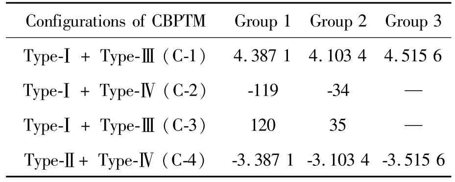
Table 1 Calculation results of transmission ratio of two-stage CBPTM
Note that the I can be increased or decreased by adjusting the epicycloid teeth and the hypocycloid teeth.In addition,the I of the configuration-2(C-2)and the C-3 were the same order of magnitude,and the transmission direction was opposite.However,the I of C-2 and C-3 were much larger than that of C-1 and C-4,indicating the C-2 and C-3 can get a larger I.Accordingly,in practical applications,in order to obtain a larger fixed I,the CBPTM should try to avoid C-1 and C-4 types.
4 Simulation of the CBPTM combined with type-Ⅰand type-Ⅳ
According to the aforementioned analysis,a twostage CBPTM with the combination of type-Ⅰand type-Ⅳwas designed,and the structural model is shown in Fig.1(b),where Z1=14,Z2=16,Z3=15,Z4=13.According to the transmission ratio formula,the I of the first-stage deceleration system was 8,and the total I of the CBPTM was 104.
To further analyze the transmission properties,the angular velocity and angular acceleration curves of the planetary disk and output disk are simulated based on the simulation software ADAMS[10],and the results are described in Fig.4.
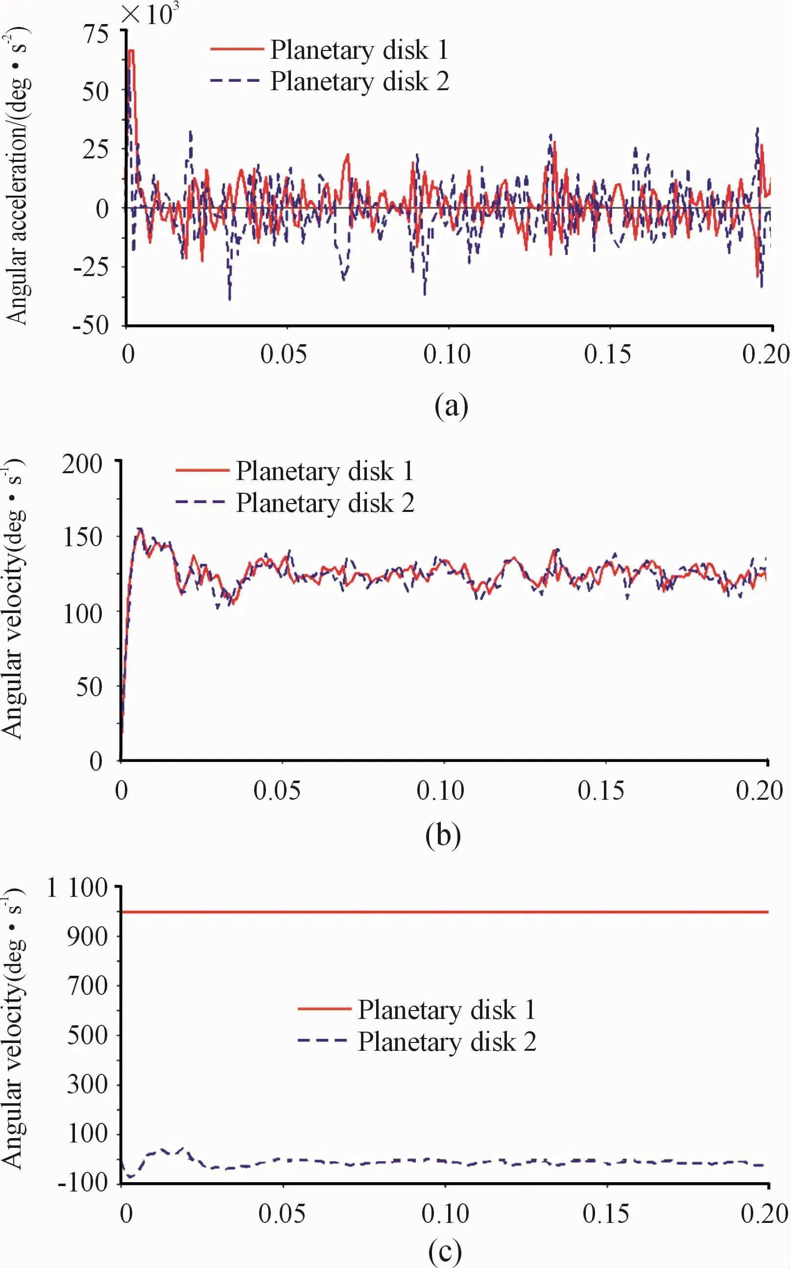
Fig.4 Angular velocity and angular acceleration curves of the two-stage CBPTM.The x-coordinate represents second(s)
It can be seen that the angular velocity curve and the angular acceleration curve of the two planetary disks were similar(Fig.4(a)and 4(b)),and the angular velocity was approximately 125(°)/s,and the angular acceleration was approximately 0.Such results were consistent with the theoretical calculation.The angular velocity curve of the output disk was approximately-9.5(°)/s,indicating that the direction of the output was opposite to that of the input,and the movement of the output disk gradually tended to be stable,indicating an equal-velocity transmission.
In Fig.4(b),the angular velocity value of the input shaft is 1 000(°)/s,and the angular velocity value of the left planetary disk is 125(°)/s.And hence the I of first-stage CBPTM was 8,and the simulation result was consistent with the initial conditions.In Fig.4(c),the angular velocity of the output disk is 9.5 (°)/s, and the total I of the CBPTM is 1 000/9.5=105,which is close to the theoretically calculated I.The results showed that the structural model of the CBPTM designed is reasonable.
5 Conclusions
The cycloidal ball transmission was a type of gapless meshing mechanism,and the transmission analysis was a fundamental work for evaluating the mechanism and movement design.By analyzing the structural principle of the CBPTM,the transmission ratios of the first-stage and the two-stage cycloidal ball transmission were derived.The result showed the transmission ratio of first-stage CBPTM was equal to half the number of the cycloid teeth,and the transmission ratio of twostage CBPTM can be calculated by adjusting the epicycloid teeth and the hypocycloid teeth.After completing the design of the CBPTM,the structural model of the transmission mechanism has been established based on the software ADAMS,and then the simulation analysis of the angular velocity curve and the angular acceleration curve were analyzed.The results show that the simulation is consistent with the design results,which provides the basis for further optimization of the designed CBPTM.
- 机床与液压的其它文章
- Lubricating performance of conical spindle distribution in the ball piston pump
- Mechanism analysis and control of asymmetrical digital cylinder
- Reliability analysis and calculationof the drive hydraulic system group of combined transportation
- Reliability analysis for cutterhead hydraulic drive system of remanufactured shield machine
- Application of compound buffer hydraulic cylinder in electro-hydraulic load simulator(EHLS)
- Start-up characteristics of a new electro hydrostatic actuator with an accumulator

