Design and key technology research of a novel plane-quadratic-envelope annular worm CNC grinding machine based on virtual center distance grinding principle
Qing-feng ZHANG
(Shanghai Material Engineering School,Shanghai 200231,China)
Abstract:For the problems encountered in the development of a novel plane-quadratic-envelope annular worm CNC grinding machine,the article analyzes the forming principle of the worm surface and the traditional grinding method,and then analyzes the virtual center distance grinding principle and key technologies of the worm surface.The feasibility of the four-axis-linkaged grinding method was also proposed,and the structural layout and overall design of the new grinding machine were also proposed.Aiming at the two problems of the large distance between the grinding processing surface and the center axis of the rotary table and the large distance between the grinding point on the grinding wheel surface and the center axis of the rotary table,an inclined grinding wheel design was proposed on the structural layout of the grinding machine as well as the design scheme of hidden grinding head,at the same time,the design of translational dressing for the dressing and compensation methods of the grinding wheel is proposed.These new schemes solved the problems of the grinding area shape and position out-of-tolerance caused by the table rotation error during the grinding process,and the virtual prototype design of the grinding machine was completed.
Key words:Virtual center distance,Plane-quadratic-envelope annular worm,CNC grinding machine,Structural design
1 Introduction
Plane-quadratic-envelope annular worm is a new product independently researched and developed by our country.It has the advantages of larger load capacity,higher transmission efficiency,better meshing characteristics,etc.It is widely used in high-speed,heavy-load and other occasions[1].At present,the application of plane-quadratic-envelope annular worm grinding and processing equipment has not reached a relatively widespread level.Although there are also equipment for processing plane-quadratic-envelope annular worms in foreign countries,the structure is complex and the price is so high.Expensive,is not conducive to the promotion of plane-quadratic-envelope annular worm processing equipment;many domestic processing equipment still remains on the transformation of lathes and grinders,and special equipment is very scarce.This has led to low machining accuracy,low machining efficiency,and high equipment failure rates when machining plane-quadratic-envelope annu-lar worm,which cannot meet market demand[2].In 2007,Professor Zhang Guanghui proposed the virtual center distance grinding principle to solve the problem of insufficient working capacity of machine tools.In 2015,Dr.Luo Wenjun proposed the method of error detection and trimming of toroidal helix.In 2016,Chen Yan and others trial-produced a four-axis-linkaged toroidal worm grinders based on the virtual center distance grinding principle,but the machine tool is more sensitive to the shape,position and size.So,even the newer four-axis-linkaged grinding machines still have the problem that the distance from the grinding point to the center axis of the linked rotary table is too large.This also causes a slight angular error at the point of the grinding wheel when the linked rotary table performs a rotary motion.The location will also be enlarged,which will cause the problem of excessive grinding surface shape of the toroidal worm[3-4].Therefore,the research and development of a new type of plane-quadratic-envelope annular worm grinding machine has very important applications for improving the processing status of plane-quadratic-envelope annular worms and the promotion and application of plane-quadratic-envelope annular worm pairs value and practical significance.
2 Forming principle of worm surface and traditional grinding method
2.1 Forming principle of worm surface
During the forming process of the plane secondary enveloping toroidal worm surface,a known plane F is used as the original plane,and a certain angle is rotated around the center axis Y of the worm’s base circle.At the same time,the rough parts of the toroidal worm are also Rotating around its own center of rotation axis Z,at this time we will call the worm developed by the two as a flat envelope toroidal worm[5],as shown in Fig.1.
As mentioned above,the formation of the planequadratic-envelope annular worm mainly includes two envelope movements,that is,the planar worm gear is first developed into an envelope worm,and then the envelope worm is developed into a desired planar worm gear.During these two developments,a planequadratic-envelope annular worm was formed.It should be noted that:(1)In the process of developing the flat envelope toroidal worm,the original plane must always be tangent to the main base circle of the worm gear and the distance between the original plane F and the center axis Y of the base circle of the worm gear the included angle isβ;(2)The toroidal worm blank’s own rotation center axis Z and the worm wheel’s base circle center axis Y are vertically staggered,different-surface straight lines in space,and the shortest distance between the two is a plane envelope torus the center distance L of the worm.
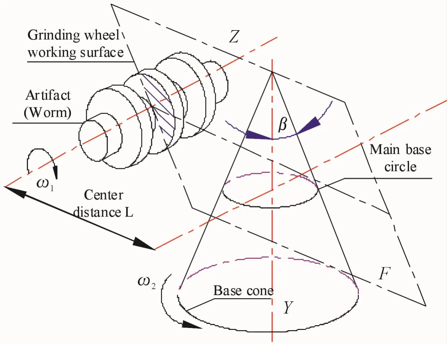
Fig.1 Plane enveloping worm gear surface forming principle
2.2 Traditional grinding method of worm surface
The traditional planar double-enveloping toroidal worm grinder is realized based on the basic principle of planar envelope grinding.Generally,such a twoaxis-linkaged grinding machine uses a rotary table with a worm and a worm as a transmission pair to drive the grinding wheel frame for rotary motion.At the same time,this grinding machine must be equipped with a multi-layer table in order to adjust the distance from the grinding point to the center of rotation and the lateral and vertical displacement of the grinding head and the compensation in the vertical direction according to different turning radii[6-7].The structure of the two-axis-linkaged grinding machine is shown in Fig.2.
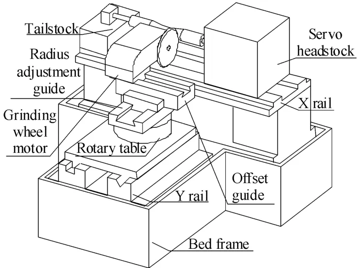
Fig.2 Structure of two-axis-linkaged grinding machine
We can easily find the following situation in the structure diagram of the two-axis-linkaged grinding machine for the above-mentioned annular worm surface grinding:
1)When the center distance of the plane-quadraticenvelope annular worm is large,the rotary table of the grinding machine must be translated a large distance backward relative to the grinding point of the grinding wheel on the worm;similarly,when the center distance of the annular worm is small,the rotary table of the grinding machine must translate a large distance forward relative to the grinding point.This results in a large reciprocating movement distance of the rotary table,and the grinding machine must have a large movement space in the lateral direction,especially when the center distance of the plane-quadratic-envelope annular worm is very small.As a result,the rotary table of the grinding machine must keep a small distance from the workpiece.However,because the grinding head is large,in order to avoid interference,the rotary table must be further retracted by a larger distance,so this further increases the structural size of the two-axis-linkaged grinding machine.
2)Since this traditional planar enveloping toroidal worm grinder must be equipped with more moving layers,the structure of this grinding machine is quite complicated,the rigidity is very poor,the operation is very inconvenient,and the machining accuracy is difficult to guarantee.In order to solve this series of problems,the overall structure size of the grinding machine must be enlarged during the design of the grinding machine,which in turn has caused the shortcomings of the large overall size of the two-axis-linkaged grinding machine and the large footprint.
3 Principle and key technology of virtual center distance grinding of worm surface
3.1 Analysis of the grinding method of four-axis-linkaged
From the perspective of the processing method of plane-quadratic-envelope annular worms,it is difficult to process worms with very large(small)toroidal center distances on traditional two-axis-linkaged machining equipment;on the other hand,the continuous development of degree technology and NCrotary technology,adopts NCrotary technology and NCinterpolation technology to approach very large(small)center distance arcs.At the same time,the three-axis linkage of X axis,Y axis,and C axis is used to ensure the work of the grinding wheel.The surface is always tangent to the base circle,so that a very large(small)center distance arc worm can be interpolated[8].
Through the analysis and research of the traditional plane-quadratic-envelope annular worm grinder and its processing methods,it is not difficult to find that:based on virtual center distance grinding principle,four-axis-linkaged grinding scheme can greatly simplify the grinding steps of the plane enveloping toroidal worm,greatly reduce the overall size of the grinding machine,make the grinding machine simple,compact,and more convenient to process and adjust,which greatly improves the application and processing range of the grinding machine[9].
3.2 Principle of virtual center distance grinding of worm surface
The principle of the virtual center distance grinding of the plane-quadratic-envelope annular worm surface is shown in Fig.3.

Fig.3 The principle of the virtual center distance grinding of the annular worm surface
In the picture:
a—The center distance of the virtual planar envelope toroidal worm;
O2—Virtual plane worm gear turning center(Revolving center);
O,Ot—Virtual plane envelope toroidal worm rotation center(Rotation center);
e,et—The actual center distance between the rotary table and the worm;
Rb— Radius of main base circle;
R—Indexing radius of the plane secondary envelope toroidal worm;
Re—The revolution radius of the rotary table(Can be adjusted through interpolation motion);
ω—Rotational angular velocity of the rotary table;
ω1—Rotational angular velocity of plane-quadraticenvelope annular worm;
ω2—Angular speed(Orbital angular speed)of the flat grinding wheel around the virtual rotation center.
It can be seen in Fig.3:if the working worm surface of the plane-quadratic-envelope annular worm is regarded as being enveloped by the genera L of the toroidal worm,then the genera L of the toroidal worm coincides with the straight line AB,During the processing of the plane-quadratic-envelope annular worm,the worm generatrix L should always be tangent to the base circle.Whenφ2=0,the worm generatrix L and the straight line AO2form△AO2B,and the triangle is coplanar with the base circle of the plane-quadraticenvelope annular worm.If△AO2B and the tool worm wheel forming a plane-quadratic-envelope annular worm are fixed together,it is regarded as a rigid connection and the effective grinding radius is R.It is also assumed that the angular speed of the worm’s rotation isω1,and the rotation angle in unit time isφ1;the angular speed of△AO2B,which is fixedly connected with the tool worm gear isω2,and the rotation angle in unit time isφ2and satisfies the relationship:

In a certain period,the worm bus bar L gradually completes the wormsurface of the toroidal worm during the rotation process.At this time,△AO2B is also rotated to the position of△AtO2Bt.This is the principle of virtual center distance grinding of worm surface,and also the basic principle of forming the virtual center distance grinding of the annular worm surface.
The following is a further analysis of the principle of the virtual center distance grinding of the annular worm surface in conjunction with Fig.3.The above is the original line L of the worm,which rotates from the position of the straight line AB to the position of AtBtaccording to the meshing relationship of the planequadratic-envelope annular worm pair.If in the plane of△AO2B and an arbitrary point O on the straight line AO2,assuming OO2=Re,passing any point O as a straight line OC∥O2B,and the foot is point C,then△AOC∽△AO2B exists,within a certain period when△AO2B and the straight line AB are rotated around the base circle’s rotation center O2through theφ2,△AtOtCt∽△AtO2Btexists,and OtO2=OO2=Re.Since the original lineL of the worm coincides with the AB side of△AO2B,the rotation locus of the original line L of the worm in the base circle plane is consistent with the rotation locus of△AOC.According to the principle of plane motion in theoretical mechanics,when△AOC rotates to the position of△AtOtCt,the trajectory of the movement can be correspondingly transformed into△AOC and the arbitrary point O together with O2as the center of the circle in the base circle plane.Reis Radius circular interpolation motion is superimposed with motion with O point as the center andωas the angular velocity.Therefore,according to the knowledge of theoretical mechanics:

According to the above analysis,we can know that when a traditional plane-quadratic-envelope annular worm grinder processes a toroidal worm,the rotary table of the grinding wheel must be installed on△AO2B.The original line L of the worm is equivalent to the production surface.All that is required is that the tool bar L of the worm be rotated around the rotation center O2of the rotary table.When performing virtual center distance grinding,the movement process of the tool bar L of the worm is the same as that of△AOC,so only the rotary table of the grinding wheel needs to be mounted on△AOC,and the rotary center of the table coincides with O.At this time,the movement of the traditional plane-quadratic-envelope annular worm grinder when machining the toroidal worm can be regarded as a circular interpolation motion of the grinding wheel in the base circle plane with Reas the radius(In the base circle plane,the X-axis and the Z-axis are used to interpolate to form an interpolation arc)and the rotary table of the grinding wheel drives the grinding wheel to perform a rotation motion around its own axis.This greatly reduces the actual diameter and center distance of the machine table and simplified the structure of the grinding machine[10].We call the above-mentioned methodthe principle of the virtual center distance grinding of the plane-quadratic-envelope annular worm surface,which is also the basis for the development of four-axis-linkaged and seven-axis-four-axis-linkaged toroidal worm grinders.
3.3 The key technologies with principle of the virtual center distance grinding
3.3.1 Determining the interpolation radius R for the X and Z axes
As shown in Fig.4,O0is the center of the base cir-cle,interpolation circle,and grinding circle.O2is the center of rotation of the grinding wheel linkage rotary table.AB is the grinding plane of the grinding wheel(The production surface),and point A is the grinding wheel ground edge point.In the process of X-axis and Z-axis circular interpolation,the change order of the rotation center of the rotary table of the grinding wheel is:O2→O′2→O″2.If the linked rotary table of the grinding wheel does not perform the turning movement,the movement track of the edge point A of the grinding wheel is:A→A′→A″.Obviously,the position of the grinding edge point of the grinding wheel greatly exceeds the contour trajectory of the grinding circle,and the center of the circle where the grinding point is located is no longer concentric with the circle center of the base circle.If the position of the edge point of the grinding wheel is always on the trajectory of the grinding circle,the grinding head must be rotated around the point O2through a certain angle to compensate,so that the movement path of the edge point of the grinding wheel becomes for:A→A0′→A″0,at the same time,the line where AB,A′0B′0and A″0B″0are located must always be tangent to the base circle,so as to meet the meshing principle of virtual center distance machining.
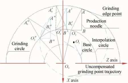
Fig.4 Motion diagram of four-axis-linkaged grinding machine
For different toroidal worms,the design parameters such as the base circle radius,the worm tip and root arc radius have been determined at the design stage,and the required grinding radius AO0is between the top of the worm and the arc of the root.In between,AB and O2B are inherent parameters of the grinding machine,which have been determined during the design phase of the grinding machine.The position of the edge point A of the grinding wheel can be determined during tool setting.Therefore,according to the above analysis,it can be known that the interpolation circle radius of the grinding wheel’s linked rotary table is the distance from the turning center O2of the grinding wheel’s linked rotary table to the center O0of the base circle.
3.3.2 Determine theangular velocity of therotary table in the B axis direction
According to the above theoretical analysis,it is found that the angular velocity of the grinding wheel’s turning center during the interpolation motion has some specific geometric relationships with the rotating angular velocity of the grinding wheel’s linked rotary table around its own turning center axis.This relationship will be determined by geometric methods below.Determine the angular velocity of the grinding wheel’s linked rotary table around its B axis.
As shown in Fig.5,the half of the grinding head,that is△O2AB,indicates the entire grinding wheel,where AB is tangent to the base circle at a time and the illustrated AB is set as the initial position of the grinding wheel.O0is the center of the base circle,the interpolation circle,and the grinding circle,and O2is the rotation center of the grinding wheel linkage rotary table.If the linked rotary table of the grinding wheel does not move,the rotation center O2of the linked rotary table of the grinding wheel is rotated around O0after the angle ofφ.In order to make the edge point A of the grinding wheel on the required grinding contour,the linked rotary table of the grinding wheel can be rotated by an angle ofθaround its own rotation center O2to reach the position of△O′2A″oB″o.The following will prove the geometric relationship between the angle ofθandφ:
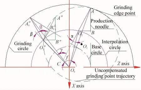
Fig.5 Rotation angle compensation chart of sand rotating table
It can be clearly seen in the figure that AB=A″oand O2A=O″2A″o;
The edge point A of the grinding wheel is on the grinding arc.AO0and A″0O0have the same radius.Therefore,among△AO2O0and△A″0O″2O0,there are AO2O0≌A″0O″2O0;
Therefore,∠AO0O2=∠A″0O″0O″2,∠AO2O0=∠A″0O″2O0.
In addition: α & βare complementary to∠AO2O0&∠A″0O″2O0,
Soα=β.
Because△AO2O0translates to△A″0O″2O0,
So AO2∥A″O″2;
Soγ=β+θ;
Becauseγis the outer angle of△O2CO0,
Soγ=α+φ;
Soφ=θhas been proven.
To sum up:In the four-axis-linkaged machining motion scheme,the angular velocity of the grinding wheel’s rotary center during the interpolation motion is equal to the rotary angular velocity of the grinding wheel’s linked rotary table about its own center axis.
4 The key structural layout and overall design of the new grinding machine
4.1 Development requirements for grinding machines
The equipment requirements for the development of a novel plane-quadratic-envelope annular worm CNC grinding machine are as follows:
1)Maximum installation diameter of the equipment:320 mm;
2)Maximum distance between the top of the equipment:1 200 mm;
3) Minimum tip distance of the equipment:150 mm;
4)Maximum weight of the workpiece:150 kg;
5)The linear motion axis:every 300 mm,the positioning accuracy is 0.002 mm,and the repeated positioning accuracy is 0.001 mm;
6)The rotary motion axis:the indexing accuracy of the rotary motion axis is 5″;
7)The rotating speed of the grinding wheel’s rotating shaft is:3 200 r/min;
4.2 The key technologies of structure layout with grinding machine
The novel plane-quadratic-envelope annular worm CNCgrinding machine is based on the principle of virtual center distance grinding.This new type of fouraxis-linkaged grinding machine is equipped with a B-axis table that can rotate on a single-layer guide rail in the X-axis direction;and a C-axis that can drive an envelope toroidal worm on a single-layer guide rail in the Z-axis and fixture attachments.When the X-axis and Z-axis are linked to form an interpolation circle,the rotating B-axis table and the grinding head on the B-axis rotating table are driven,so that the grinding head can perform circular interpolation with respect to the toroidal worm movement[10-12].In addition,while the grinding head performs circular interpolation motion,the linked rotary table of the grinding wheel is also rotating in the B axis around its own rotation axis,which in turn drives the spindle grinding wheel to also perform the rotating motion in the B axis.At the same time,it can also ensure that the production surface of the grinding wheel is always tangent to the base circle and that the included angle with the center axis of the rotary table is constant.In this new type of grinding machine,the X-axis and Z-axis are linked to form an interpolation circle,plus the rotation of the B-axis and the C-axis of the toroidal worm around its own axis to form a four-axis linkage of the grinding machine.The structure of the new four-axis-linkaged grinding machine is shown in Fig.6.
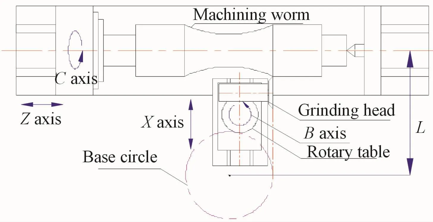
Fig.6 The structure of four-axis-linkaged grinding machine
During the development of the novel plane-quadratic-envelope annular worm CNC grinding machine:the design of the grinding head components is the most important thing in the development of grinding machines.On the one hand,the grinding head must participate in the four-axis-linkage,and the mutual cooperation relationship between the four axes must be guaranteed;on the other hand,the grinding head part is also set up with the grinding wheel before the secondary enveloping toroidal worm machining,and the dressing process of the grinding wheel is closely linked.Therefore,the factors that need to be considered in the design of grinding head components are:
1)How to ensure that the helix angleβbetween theprofiling surface of the grinding wheel and the central axis of the base circle is adjusted before the worm grinding;
2)How to ensure that the grinding point of the grinding wheel and the axis of rotation center of the worm are always in the same horizontal plane before the worm is ground;
3)How to ensure that the production surface of the grinding wheel and the main base circle are always tangent in space during the worm grinding process;
4)How to ensure that the shaped surface of the grindstone after trimming is still tangent to the main base circle in space.
During the development of the novel plane-quadratic-envelope annular worm CNC grinding machine,in order to solve the above problems,and from the grinding processing surface to the center axis of the swinging rotary table and the grinding point of the grinding wheel surface to the center axis of the linked rotary table for the problem of too large distance,this article first proposed the design of the grinding wheel inclination type grinding head and the design scheme of hidden grinding head,as shown in Fig.7.
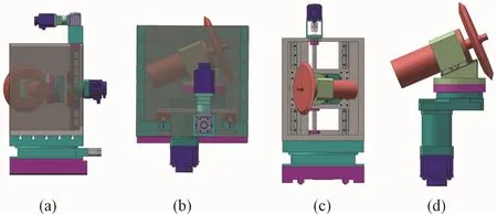
Fig.7 Structural design of the grinding head of the novel grinding machine
This solution successfully reduced the shortest distance between the grinding point of the grinding wheel on the production surface to the center axis of the swing table of the swinging head to“zero”;at the same time,the shortest distance of the grinding point on the production surface of the grinding wheel to the center axis of the linked rotary table the distance is greatly reduced,which solves the problem of excessive grinding wheel shape and position caused by the rotation error of the linked rotary table during the grinding process,and meets the needs of actual production.
4.3 Configuration plan of grinding machine
In this paper,after full analysis and careful selection,on the basis of the virtual center distance grinding principle of novel plane-quadratic-envelope annular worm CNCgrinding machines and new type of fouraxis-linkaged grinding machines,a new seven-axisfour-axis-linkaged toroidal worm grinder was developed.The motion configuration scheme is as follows:
The four-axis-linkage system includes:the longitudinal feed motion of the table(Z axis);the lateral feed motion of the pallet(X axis);the rotary motion of the rotary table(B axis)and the rotary motion of the workpiece itself(C axis).In the new four-axis linkage system of the new plane-quadratic-envelope annular worm CNC grinder,a shaft system with servo function is used.
In the novel plane-quadratic-envelope annular worm CNC grinding machine,the rotary motion of the grinding wheel is the main motion of the grinding machine(SP axis).This movement is driven by the grinding electric spindle,which can achieve constant linear speed grinding in the grinding of plane-quadratic-envelope annular worms.In addition,in order to adjust the position of the grinding wheel production surface,the new type of plane-quadratic-envelope annular worm CNC grinder also needs to be equipped with an adjustment axis(A axis)for the inclination angleβof the grinding wheel production surface and a compensation axis(Y axis)for the grinding head in the height direction.
In addition,in the new grinding machine:the lateral feed motion axis(X axis)of the pallet,the height compensation axis(Y axis)of the grinding head and the longitudinal feed motion axis(Z axis)of the table all adopt AC servo motor,and realize the feed and compensation function of each axis through the direct connection of flexible plum coupling and ball screw;AC servo motor is also used in the rotary motion axis(C axis)of the workpiece itself.The flexible plum blossom coupling is directly connected to the main shaft to drive the dual-center automatic clamping device and the workpiece to perform rotary motion.The clamping of the workpiece uses the clamping scheme of the main shaft center and the hydraulic tailstock.In addition,the new grinding machine also uses a polycrystalline diamond pen to dress the grinding wheel.Because the novel plane-quadratic-envelope annular worm CNC grinding machine adopts the design of the grinding wheel inclination type grinding head and the spindle translation sanding design in the structural design,when the grinding wheel is dressed,the trim-ming the wheel with sufficient feed can ensure the flatness of the production surface of the wheel and the accuracy of the grinding point position.
4.4 Overall layout design of the grinding machine
In the overall layout design of the new type of plane-quadratic-envelope annular worm CNC grinder,the overall size of the grinding machine is:4 200 mm×3 200 mm×2 100 mm,which is mainly composed of the bed,column,grinding head,headstock,and tailstock,and feed system,electrical accessories,et al.The overall layout is shown in Fig.8.

Fig.8 The overall layout design of novel plane-quadratic-envelope annular worm CNC grinder
The main technical parameters of the novel planequadratic-envelope annular worm CNC grinder are as follows:
1)The working area of a table:1 655 mm×600 mm;
2) The longitudinal feed stroke of the table:1 800 mm;
3)Transverse feed stroke of drag plate:1 000 mm;
4)Rotation angle range of linked rotary table:±60°;
5)Worm center distance processing range:100~500 mm.
The machining process of the new plane-quadraticenvelope annular worm CNC grinder is as follows:firstly,the blank of the plane-quadratic-envelope annular worm is placed between the headstock and the tailstock and the workpiece is rotated by the automatic clamping chuck,and the grinding wheel It is mounted on the grinding head component,and the column and the grinding head component make the rotary motion together by the grinding wheel linkage rotary table.The table and the carriage are driven by the screw nut pair to achieve the lateral and longitudinal feeding during the grinding process motion.During the entire machining process,all instructions are issued by the CNC system,which realizes the automatic machining of the workpiece.
5 Conclusion
During the development of the novel plane-quadratic-envelope annular worm CNC grinding machine,this paper addresses two problems:the distance between the grinding processing surface and the center axis of the rotary table is too large and the distance between the grinding point and the center axis of the rotary table is too large.For the first time,the design of the grinding wheel inclination type grinding head and the design scheme of hidden grinding head was proposed.In addition,a new design of the spindle translation sand repair is proposed for the grinding wheel dressing and compensation method.The proposal of these new schemes theoretically reduces the shortest distance from the grinding plane to the center axis of the rotary table to“zero”,and also greatly reduces the shortest distance from the grinding point of the grinding wheel to the center axis of the rotary table,thereby solving the problem.The problem that the shape and position of the grinding area caused by the rotation error of the table during the grinding process exceeds the tolerance range is met,which meets the needs of actual production,improves the current status of machining of the plane-quadratic-envelope annular worm,and also the plane-quadratic-envelope annular worm gear pair has played a positive role in the promotion,application and popularization.
- 机床与液压的其它文章
- Lubricating performance of conical spindle distribution in the ball piston pump
- Mechanism analysis and control of asymmetrical digital cylinder
- Reliability analysis and calculationof the drive hydraulic system group of combined transportation
- Reliability analysis for cutterhead hydraulic drive system of remanufactured shield machine
- Application of compound buffer hydraulic cylinder in electro-hydraulic load simulator(EHLS)
- Start-up characteristics of a new electro hydrostatic actuator with an accumulator

