Design of an automatic arrangement device for slender rod-shaped materials
Xian-da WANG,Lei HE,Yan-yan MENG,De-bo XUE
(School of Mechanical Engineering,Shandong University of Technology,Zibo 255000,China)
Abstract:Aiming at the current situation of difficult arrangement of slender guide bars,high labor intensity and low production efficiency in the flexible guided three-dimensional weaving technology.A slender rod-shaped material automatic arrangement device is designed.The device is composed of a feeding system and an arrangement system.Its working principle,overall structure and control scheme are introduced.The feeding system uses a roller to scroll the rod-shaped material to fail to realize the interval Feeding,the arrangement system realizes the switch of two arrangement methods by replacing the front end.The device has a novel structure and strong versatility,reduces the production cost of three-dimensional fabrics,and has high engineering application and promotion value.
Key words: Three-dimensional weaving, Arrangement device, Working principle, Overall structure,Control scheme
The three-dimensional fabric has unparalleled mechanical properties and is commonly used in various industries.As a new forming process,the flexible-oriented three-dimensional weaving technology solves the problems of difficulty and high cost of forming threedimensional fabrics.The closely spaced precision tiny holes form a guide template.Multiple guide templates are seamlessly attached together.Thousands of guide rods are fixed in the guide holes.During weaving,X is placed in the channel formed by the guide rods.Y-direction carbon fiber,Z-direction takes up space by the guide rod,after the corresponding thickness is completed,the Z-direction rod is replaced with carbon fiber[1-3].
1 Existing problems and cause analysis
Placing the guide rods in the guide holes to form a woven array is the core problem of the entire weaving process.The principle is that the slender guide rods need to pass through the corresponding holes position of the multi-layer guide template in sequence.The spacing of the guide template holes is 2.4 mm,and the diameter of the guide holes is 1.5 mm.The length of the rod-shaped material is 400 mm,and the diameter is 1.2 mm.At present,the arrangement is only completed by hand.The narrowness,the higher the density of the arrangement,and the larger the number makes the operators tired.At the same time,the arrangement period is longer,which takes up half of the entire process.
Freeing labor from the boring and repetitive arrangement process is currently a problem that needs to be focused on.It not only helps to reduce production costs,but also benefits the development and application of three-dimensional fabrics,which fully meet theneeds of actual production.This article proposes an automatic arrangement of slender rod-shaped materials with a frame structure.It has the characteristics of simple structure and convenient operation.It can realize automatic feeding.It changes the previous manual single-line arrangement process.It is realized by mechanization.Hours of continuous operation.

Fig.1 The principle of flexible guided three-dimensional weaving
2 Working principle and structure of an automatic arrangement device for slender rods
This paper considers the slender and soft physical characteristics of the guide rods and the process requirements for the arrangement,and comprehensively considers the feeding and arrangement process requirements and physical characteristics of the slender rodshaped materials.The arrangement device is mainly composed of a feeding system and an arrangement system.The three-dimensional diagram of the overall structure is shown in Fig.2.

Fig.2 Automatic arrangement device of slender rods
The feeding system adopts the principle of vibrating screen screening[4-7],the slender rod-shaped material is spit out from the lower discharge port in an orderly manner under the combined movement of the vibrating motor,and the falling state of the rod-shaped material is controlled by a pair of rollers squeezing each other.Considering the difference between the diameter of the rod-shaped material and the diameter of the guide hole,the discharge port is only an auxiliary guide function.
The arrangement system has two arrangement methods:single arrangement and block arrangement.Modular design is adopted.Single arrangement is used in conjunction with the feeding system.The arrangement system is directly below the feeding system and the guide rod is used Gravity Completes the positioning and directional arrangement.
3 Structural design of automatic feeding system
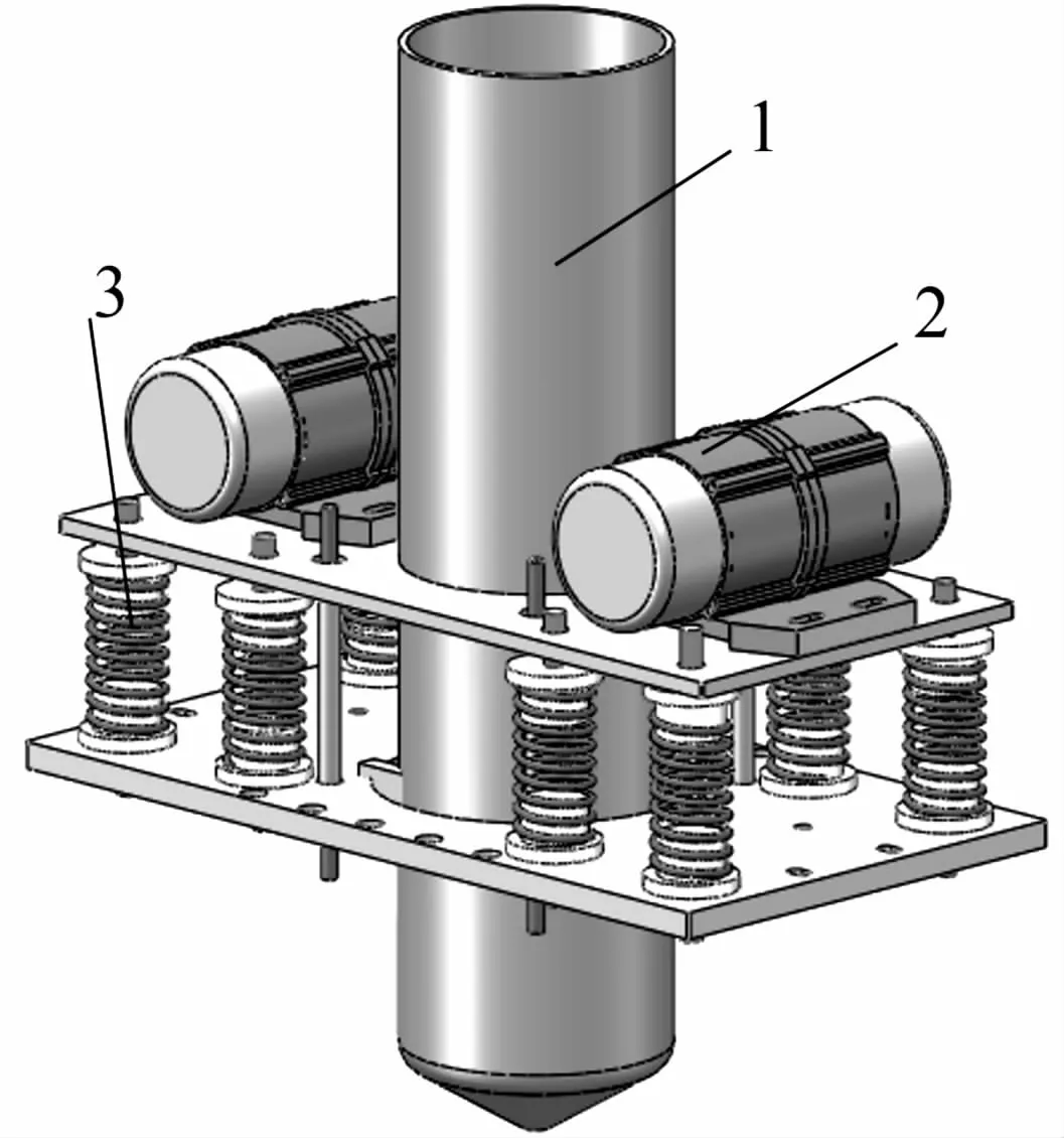
The automatic feeding system is only used when a single line is arranged,and it is mainly composed of a vibrating hopper,a vibrating motor,and a damping spring.The vibrating motor is used as the power source,as shown in Fig.3.The bottom of the vibrating hopper is cone-shaped,and there is a micro-hole that only allows a single guide rod to pass through.The reciprocating motion of the guide rod is driven by the movement of the vibration motor,and the damping spring can reduce the impact on the frame.The dynamic feeding system is installed on the motion system to meet the requirements of the feeding system to move with the arrangement system.

Fig.3 Bar material automatic feeding system
A large number of slender rod-shaped materials are placed in the cylindrical vibrating hopper along theaxial direction,and the vibration motors installed on both sides of the vibrating hopper are combined as shown in Fig.4 to realize the up and down reciprocating movement of the vibrating hopper and reduce the existence of damping spring In order to affect the vibration of other parts,the rod-shaped material is spit out orderly from the only discharge port at the bottom of the vibrating hopper under the combined action of its own gravity,inertial force and friction.

Fig.4 Vibration motor motion synthesis
The motion equation of the vibrating hopper can be obtained by analyzing the working principle of the vibrating motor:

Where S is the displacement of the vibrating hopper in the direction of vibration,λis amplitude of vibrating hopper,ωis angular velocity of vibration motor,t is operating time of vibration motor.
Assuming that the combined vibration direction of the vibrating motor is parallel to the axis of the vibrating hopper,the vibrating hopper and the vibrating motor have the same law of motion.Solving the first and second derivatives of the motion equation of the vibrating hopper along the axis can get the vibrating hopper in the axis direction.The displacement,velocity and acceleration equations:

Since the single arrangement process of rod-shaped materials is not continuous,a pair of rollers that are compressed and coincide with the center axis of the vibrating hopper are designed at the outlet of the vibrating hopper,as shown in Fig.5.The center distance of the two rollers can pass.The micrometer is finetuned,and the rollers are driven to rotate inward by the stepping motor.The rod-shaped material discharged from the discharge port of the vibrating hopper when it is working enters the middle of the two rollers,and the roller is driven by the stepping motor to uncontrollably free the rod-shaped material.The falling body motion is converted into a controllable mechanical scroll.

Fig.5 Active roller pair
4 Structure design of arrangement system
The first step is to arrange the pieces in blocks.The arrangement system shown in Fig.6 is designed.The elongated rod-shaped material is placed vertically in the discharge hopper.The contact shape of the rodshaped material and the guide template affects the arrangement process.It is easiest to arrange when the two are vertical[8].A combination of horizontal cylinder and vertical cylinder is used to realize the movement of the rod-shaped material on the guide template.The U-shaped claw is installed on the horizontal cylinder to facilitate the gripping of the rod-shaped material.The two cylinders in the horizontal direction extend out to clamp the tail of the rod-free material.The vertical cylinder extends to drive the rod-shaped material upward,then the horizontal cylinder loosens the clamped rod-shaped material,the vertical cylinder returns to the original position,repeat the above process many times to complete the arrangement of the guide template in this part,plane X/Y Driven by the servo motor 1 and the servo motor 2,the Y linear module sequentially moves along the guide holes on the entire template to complete the block arrangement.
The second step of the single-arrangement is based on the completion of the block arrangement.When the single-arrangement scheme is adopted,it needs to be used in conjunction with the automatic feeding system,and the detachable type shown in Fig.6 is designed.The front end of the hopper,the detachable hopper is fixed to the lower part of the hopper by bolts,the central axis of the outlet of the detachable hopper at the front coincides with the axis of the guide hole,and the automatic feeding system sorts out A single rod-shaped material falls into the installed hopper,and slides under its own gravity to the outlet ofthe center of the funnel.A photoelectric switch is provided at the outlet.The photoelectric switch detects the passing of the rod-shaped material and controls the automatic feeding device and the roller.The connected servo motor rotates.

Fig.6 Structure design of automatic arrangement system

Fig.7 Front end of detachable layout hopper
5 Control system design
1)Control system requirements
The control system requirements of the entire device:① In a single arrangement,the automatic feeding system and the automatic arrangement system also need to be used in conjunction with each other on the premise of completing their own functions;② Because the center distance of the guide holes on the guide template is small When the single-arrangement scheme is adopted,the control system should make the corresponding module have higher stability and repeated positioning accuracy;③ Can be intuitively and easily controlled in the man-machine interface.
2)Control system hardware design
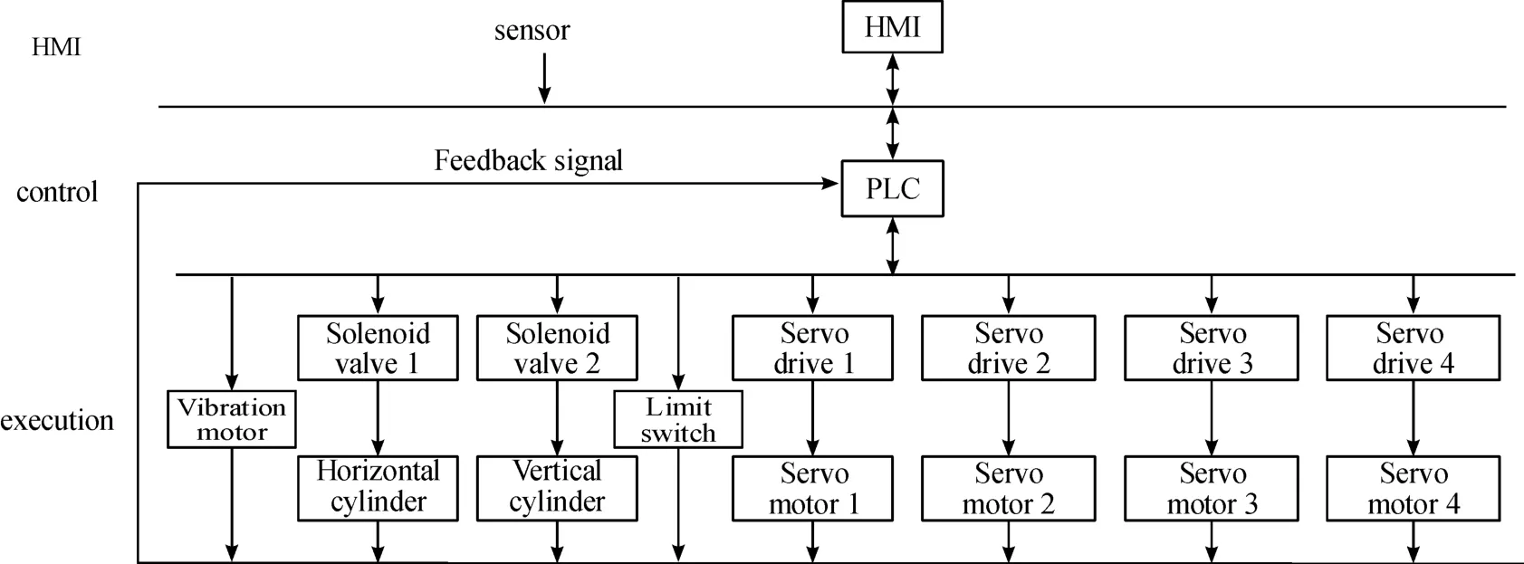
Realize human-computer interaction in the whole operation process,feedback the working status of the system to the display screen in real time,adopt PLC to control the automatic feeding system,the block arrangement system,and the single arrangement system to coordinate the movement in an orderly manner.At the same time,it needs to use a series of sensors to assist the operation.The photoelectric sensor detects the passing of the rod material in a single arrangement and feeds it back to the PLC to control the rotation of the roller pair.In the single arrangement,a red cross laser is used for positioning and the solenoid valve is during block arrangement,control the cylinder group to realize simulated vibration.After the block arrangement is completed,use the image sensor to collect the rearranged guide hole information and transmit it to the PLC.The servo motors1,2,3,and 4 respectively control the arrangement system and the The X/Y movement of the material system builds the hardware framework of the control system as shown in Fig.8[9].

Fig.8 Control system hardware framework
3)Control system flow chart
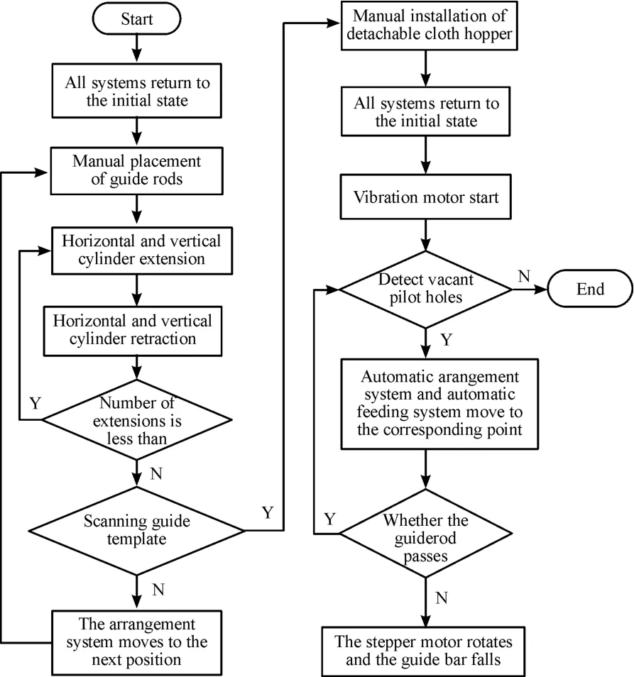
The arrangement device is designed by the arrangement plan,and the control plan of the entire device is determined according to the requirements of the process.The control process is automated,and the closed-loop feedback design minimizes manual participation.
The control flow chart design shown in Fig.9 is completed under PLC.

Fig.9 Control flow chart
6 Conclusion
According to the arrangement characteristics of slender guide rods,this paper designs an automatic arrangement device for slender rods.The device can adopt two different arrangements.The whole machine includes a feeding system and an arrangement system,which realizes The automatic arrangement process of slender rods changes the current situation of manual arrangement one by one,realizes continuous production,saves a lot of manpower and material resources,and further improves the automation of three-dimensional weaving,which is conducive to reducing costs and improving production efficiency.The expansion of the development and application of three-dimensional fabrics indirectly promotes the development of the manufacturing industry.This device can realize the automatic feeding of rods with a diameter of 1.2 mm or more and a length of 400 mm or more,and it also provides a reference solution for the automatic feeding of slender rods in the future.
- 机床与液压的其它文章
- Lubricating performance of conical spindle distribution in the ball piston pump
- Mechanism analysis and control of asymmetrical digital cylinder
- Reliability analysis and calculationof the drive hydraulic system group of combined transportation
- Reliability analysis for cutterhead hydraulic drive system of remanufactured shield machine
- Application of compound buffer hydraulic cylinder in electro-hydraulic load simulator(EHLS)
- Start-up characteristics of a new electro hydrostatic actuator with an accumulator

