Multi-UAV coordination control by chaotic grey wolf optimization based distributed MPC with event-triggered strategy
Yingxun WANG, Tin ZHANG, Zhiho CAI, Jing ZHAO,*, Kun WU
a School of Automation Science and Electrical Engineering, Beihang University, Beijing 100083, China
b Flying College, Beihang University, Beijing 100083, China
KEYWORDS
Abstract The paper proposes a new swarm intelligence-based distributed Model Predictive Control (MPC) approach for coordination control of multiple Unmanned Aerial Vehicles (UAVs).First,a distributed MPC framework is designed and each member only shares the information with neighbors. The Chaotic Grey Wolf Optimization (CGWO) method is developed on the basis of chaotic initialization and chaotic search to solve the local Finite Horizon Optimal Control Problem(FHOCP). Then, the distributed cost function is designed and integrated into each FHOCP to achieve multi-UAV formation control and trajectory tracking with no-fly zone constraint.Further,an event-triggered strategy is proposed to reduce the computational burden for the distributed MPC approach, which considers the predicted state errors and the convergence of cost function.Simulation results show that the CGWO-based distributed MPC approach is more computationally efficient to achieve multi-UAV coordination control than traditional method.
1. Introduction
Unmanned Aerial Vehicles (UAVs) are found to have a wide utilization in military and civilian fields, such as reconnaissance, surveillance, precision agriculture, cargo transportation and forest firefighting.1–8Compared to a single platform, the superiority of multiple UAVs is shown in the performance of complex missions, such as salvage, cooperative exploration and battle.9–13Coordination can improve the abilities of detection, localization and perception, which is conducive to mission assignment, in-flight refueling and reconfiguration for multiple UAVs.
There are typical methods for multi-UAV coordination control, such as leader–follower strategy, consensus theory,differential game, etc.14–26Based on a non-smooth backstepping design, a consensus algorithm is proposed for coordination control in the three-dimensional space.14A distributed cooperative control protocol proposed for multi-UAV formation is simulated and its effectiveness in implementing formation reconstruction is verified.15In order to prevent collisions in UAV swarm, a control algorithm is designed, which uses consensus algorithm, artificial potential field method and leader–follower strategy.16The problem of formation reconstruction control of multiple UAVs is solved by solving the time optimal problem. The effectiveness of this method is tested with the formation under the leader follower strategy by simulation, and the security of tracking is also enhanced.17On the basis of binary-tree network, a feedback controller is proposed, which reduces the burden of computation. Its performance in coordinated control of multiple UAVs is tested by simulation.18Based on Model Predictive Control (MPC), a coordination control algorithm is developed, and its effectiveness for formation control and obstacle avoidance is experimentally verified.19
MPC has advantages in multi-UAV coordination control.27–31A cooperative control method for multiple UAVs in two-dimensional plane is proposed,and the collision avoidance is realized by the cost function of MPC. The verification of this control method is given by the simulation of two groups of UAVs.27However, MPC with time-triggered mechanism updates the control continuously. It is unnecessary and increases the burden of computation in some cases. Eventtriggered strategy decreases the frequency of updating and can be combined into the MPC scheme to relieve the burden of computation. Optimal Control Problems (OCPs) are typically to find an optimal control law or design an optimal control program or system according to different kinds of research objects. For the Finite Horizon Optimal Control Problem(FHOCP), the solution needs to be found in each prediction horizon. The swarm intelligence-based optimization methods,such as Particle Swarm Optimization (PSO), Brain Storm Optimization (BSO), and Grey Wolf Optimization (GWO),can be used for the solution of FHOCP in MPC. In order to increase the global convergence speed and global search mobility, this paper proposes a CGWO-based distributed MPC approach for multi-UAV coordination control.
The main contribution is summarized in the following part: (A) the CGWO is designed on the basis of the chaotic initialization and chaotic search, which is used to solve the FHOPC for each UAV; (B) the distributed cost function is designed for each FHOCP to achieve UAV formation control and trajectory tracking; (C) the event-triggered strategy is developed to lessen the burden of computation for the multi-UAV coordination control. The organization of the paper is described as follows. Section 2 introduces the preliminaries that include the motion model of multiple UAVs,nonlinear MPC and the GWO. Section 3 gives a detailed description of the CGWO-based distributed MPC approach.Section 4 presents the numerical simulations that are performed to test the designed CGWO-based distributed MPC approach. Finally, conclusion and direction of further research are introduced in Section 5.
2. Preliminaries
2.1. Model
Assume that a UAV formation consists of N UAVs in a horizontal plane,and each UAV can be regarded as a mass point.The motion state zi=[pix,piy,θi,vi]Tcan be expressed as

where the position is pi=[pix,piy]T, viindicates the linear velocity, θiis the yaw angle, ωiis the angular velocity, and aiis the acceleration.Fig.1 shows the motion of multiple UAVs.
2.2. Nonlinear MPC
The system is given by

where the prediction horizon is defined as s ∈[tc,tc+Tp].The optimal predicted control input u*(s;tc) is based on the predicted state z(s;tc)and the control input u(s;tc),which are limited by the state constraint Z and the control constraint U.The cost function J consists of F and Φ. F is a running function which is decided by different flight missions. The detailed description will be presented in Section 3.1. Φ is a terminal state penalty function.

Fig.1 Motion of multiple UAVs.
2.3. Grey wolf optimization (GWO)
The inspiration for GWO comes from the social behaviors of grey wolves which have two interesting social behaviors,including the strict social hierarchy and the hunting mechanism. Fig.2 shows the principles of GWO. Grey wolves can be divided into four ranks,α,β,δ as leaders and ω as subordinate.32GWO mimics this social hierarchy by regarding the fittest solution as α,the second fittest solution as β,and the third fittest solution as δ.Other candidate solutions are defined to be ω. The optimization process of GWO mimics the hunting mechanism of grey wolves.ω wolves follow three high-level wolves α,β and δ,and update the locations at random to encircle the prey.


where tgis the current iteration, and Diis the distance vector.The symbol ||is used to obtain the absolute value of each element in the matrix. The position vector of the prey is Xp(tg),which represents the optimal solution. The coefficient vectors Aiand Ciare obtained by

where r1and r2are random vectors,and each element of them ranges from 0 to 1.Components of aiare calculated by the formula 2-2tg/tmax,where tmaxis the maximum iteration.Therefore, Components of aireduces linearly from 2 to 0 as the number of iterations increases.

Fig.2 Principles of GWO.
Gray wolves usually know the location of the prey during predation, which represents the optimal solution. But during the optimization process, the optimal solution is obviously unknown. Suppose that the leadership wolves α,β and δ have advantages in obtaining the potential location of the prey.Taking the locations of leader wolves as the location of prey into Eqs. (8) and (9), the assumed location of the prey can be updated based on the three locations as

where Xα, Xβand Xδare three position vectors of α, β and δ wolves;X(1),X(2)and X(3)are position vectors of the first three fittest solutions.
3. CGWO-based distributed MPC approach
3.1. Framework
The dynamics for UAV i ∈V ={1,2,...,N} is given by

andthen,z = [z1,z2,...,zN],u = [u1,u2,...,uN]and f (z ,u)=[f1(z1,u1),f2(z2,u2),...,fN(zN,uN)] represent the concatenated vectors in the system (2). In this paper, the mass point model is used to describe the dynamics of UAV motion by Eq. (1), which can be written as the system model by Eq.(14).The controller of the proposed CGWO-based distributed MPC approach is designed on the basis of the mass point model.
For Problem 1,the state is usually coupled in the integrated cost function for the multi-UAV coordination control. The running function in Eq. (4) is given by

where F1(z(t),u(t)) represents the formation distance constraints, F2(z(t),u(t)) represents the formation angle constraints, F3(z(t),u(t)) is for reference trajectory tracking, and w1,w2and w3are weight constants.
The terminal state penalty function in Eq. (4) can be expressed as

where the vector norm in Rnis represented by ‖ ‖, γ is the weight constant,and r(t)is selected according to flight mission.
The cost function including Eqs. (15) and (16) reflects the motion of UAVs in traditional MPC approach entirely. However, it demands powerful computation and would be ineffective in the case of communication limitation. Fig.3 shows the communication limitation in the network of UAV formation.The direct message exchange of UAV i is merely available in the set Ni, and Niis the number of UAVs which are in the set Ni. Correspondingly, N~iis the set that consists of nonneighbors of UAV i, which exchange message with UAV i indirectly.

Fig.3 Communication limitation in the network of UAV formation.

First,the control input of each UAV is initialized in the distributed MPC, and the estimated control trajectories are exchanged. Then, the event-triggered strategy judges whether the triggering conditions are satisfied to decide whether the FHOCP should be solved. The CGWO is used to solve the FHOCP and returns the predicted control input to the distributed MPC. Finally, the state of each UAV is updated.
3.2. Generation of estimated control input and state


Fig.4 CGWO-based distributed MPC approach.
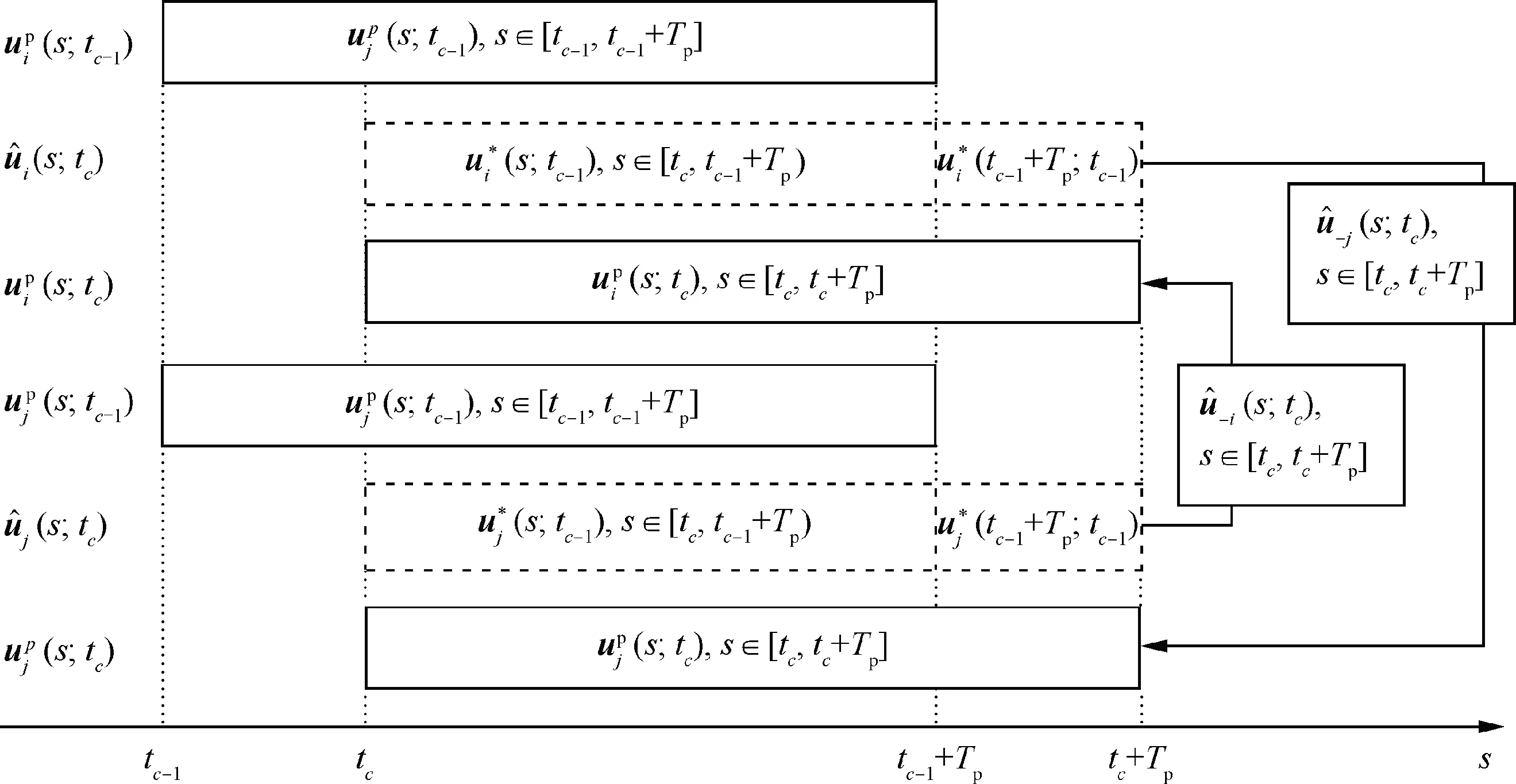
Fig.5 Estimated control inputs and states among neighbor UAVs.

Using Eq. (17)-Eq. (19), the estimated control inputs and states of the neighbor UAVs can be obtained.
Estimated control inputs and states among non-neighbor UAVs are shown in Fig.6.In the case of communication limitation, the communication between UAV i and its nonneighbor UAV k is indirect and its neighbor UAV j functions as a medium. Assume that UAV k is a neighbor of UAV j,i.e.k ∉Ni,j ∈Niand k ∈Nj. For UAV i, the estimated control input of UAV k is given by


Fig.6 Estimated control inputs and states among non-neighbor UAVs.


3.3. Chaotic Grey Wolf Optimization (CGWO)
In this subsection, Chaos Optimization Algorithm (COA) is integrated into the traditional GWO to develop the CGWO for solving FHOCP. COA is a global optimization algorithm inspired by chaos phenomenon that shows uncertain and unpredictable behaviors. Fig.7 shows the principle of the CWO. To strengthen the ability of global optimization and the performance of convergence, the chaos optimization strategy is utilized in the parameter setting and the optimization mechanism of GWO. In detail, the chaos initialization and the chaotic variable are designed to improve the parameter setting.The optimal position of each individual,enhanced leadership and the chaotic search strategy are designed to improve the search mechanism.

Fig.7 Principle of CGWO.
In the traditional GWO, the positions of grey wolves and their distances from the prey are related to the coefficient vectors Aiand Ci. Aiis constrained in [-2ai,2ai], the variation range of Aiwill decrease along with the reduction of a. It is worth mentioning that Ai| |<1 obliges the wolves to approach the prey, while Ai| |>1 forces the wolves to diverge from the prey. In other words, the linear decline of aifrom 2 to 0 lays the stress on exploration and exploitation, respectively. For a meta-heuristic, exploration indicates the ability to search the global optimum, and exploitation represents the ability to search the local optimum.In the traditional GWO,Ciremains random all the time to enhance the exploration, but it reduces the convergence rate to some extent. In CGWO, a hybrid method for the parameter setting and search mechanism is proposed to enhance the exploration. The initial values have a great influence on the exploration of a meta-heuristic. The chaos initialization can be included in the parameter setting to reduce the dependence on initial values and increase the ability of search in the initial stage by chaotic mapping. The number of grey wolves is Ng.Table 1 shows examples of chaotic mappings. The chaotic mappings are used to generate 2×Ngsolutions which are sorted by the fitness values, and the odd items of that are selected as the initial solutions. In addition, the chaos variable can be included in the parameter setting. The parameter aiis generated by chaos operators instead of linear reduction to enhance the convergence rate.
Eq. (13) shows that the optimal value is the average of the first three optimal solutions,which are obtained from the leadership wolves at current iteration time.It indicates that the traditional GWO ignores the best personal position of each wolf.In other words, it merely takes into account the global best positions, and does not memorize the individual experience of each member in the populations. To enhance the exploration of CGWO, the optimal position of each individual can be included in the search mechanism, which is given by


where f(.) represents the fitness of each wolf.
Then, the chaotic search strategy is included in the search mechanism to enhance the exploration.Generally,the increase of the global searching ability will reduce the convergence rate of the algorithm.To reduce this effect,a greedy strategy of differential evolutionary method is integrated to the chaotic search strategy. Fig.8 shows the implementation procedure of the CGWO. Each UAV in the formation needs to solve the FHOCP in the designed CGWO-based distributed MPC approach. Each wolf represents a candidate solution of FHOCP. In each iteration of CGWO, leader wolves α,β and δ represent the first three fittest solutions.
Step 1. The search scope of the solution space is limited in[Xmin,Xmax] and Xi(tg+1) can be mapped to the range (0,1).The map formula is shown as

Table 1 Examples of chaotic mapping.

Step 2. The number of iterations of chaotic map is Cmax,and a set of chaotic variables is ϑ(m),m =1,2,...,Cmax.ϑ(m)is calculated by the chaotic map iteratively, and then, it can be used in the inverse map to obtain the chaotic solution sequence

Step 3. The best solution is selected from the chaotic solution sequence based on the fitness values


Fig.8 Implementation procedure of CGWO.
Step 4. The greed threshold is defined as ξG, and the new formula of location updating is given by

where r3is a random number in the range[0,1].
3.4. Formation control and trajectory tracking
The CGWO is proposed to solve the FHOCP and find the optimal predicted control input of each UAV by comparing the value of cost function. In traditional coordination control approach, the cost function is expressed as Eq. (15). In the CGWO-based distributed coordination control approach, the distributed cost function can be expressed as

where wi1,wi2and wi3are weight constants.
Fi1(zi(t),ui(t))represents the distance constraints of formation, and it is given by


Fi2(zi(t),ui(t)) represents the angle constraints of formation, and it is given by


The distributed running function of UAV i for distributed MPC approach is given by

The no-fly zone constraints also need to be considered in the distributed cost function. Any no-fly zone can be replaced by a circular no-fly zone. Fig.10 illustrates the geometry relation between UAV i and no-fly zone.R is the radius of a no-fly zone. diis the distance between the center of the no-fly zone and UAV i. σi∈(-π,+π) is the angle between viand di. If di→R and σi| |→0 are satisfied, it is indicated that the UAV i are approaching the no-fly zone.
To ensure the safety of UAVs, any UAV had better not enter a certain zone that can be named as safe zone, and dsafeis the radius of the safe zone. If σi| |<π/2 is satisfied, UAV i is possible to enter the no-fly zone, while the UAV i will fly away from the no-fly zone if σi| |>π/2 is satisfied.
To integrate the no-fly zone constraints into the distributed cost function, the no-fly zone constraint can be described as a penalty term, which is given by

Fig.9 Illustration of formation constraints.

3.5. Enhanced event-triggered strategy


Fig.10 Geometry relation between UAV i and no-fly zone.


Fig.12 Triggered instants of each UAV.

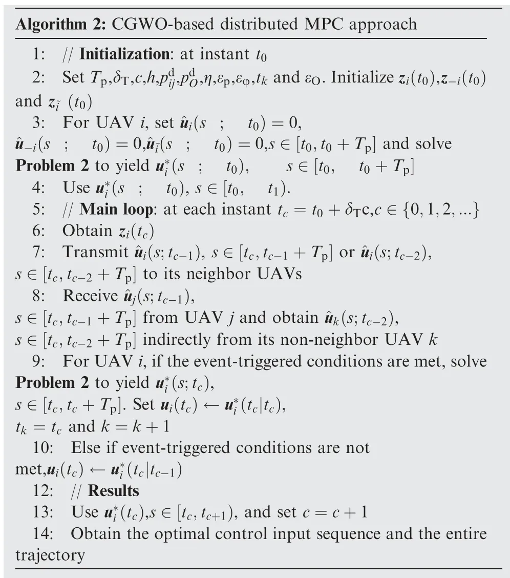
Based on the event-triggered strategy, Algorithm 2 shows the pseudo-code of the proposed approach.
4. Numerical simulations
In this section, the performance of the designed distributed MPC approach is examined by numerical simulations. The coordination control of three UAVs is considered in the simulation scenario. The performed simulations are shown in Table 2. First, the circular reference trajectory is selected to test the CGWO-based distributed MPC approach. Then, the event-triggered strategy is included in the CGWO-based distributed MPC approach. Finally, the CGWO-based distributed MPC approach with no-fly zone constraints is tested.

Table 2 Numerical simulations.

Fig.13 Communication topology used in numerical simulations.

4.1. Example 1 (CGWO-based distributed MPC approach)


Table 3 Initial states of formation.

Fig.14 Ground tracks of UAVs by CGWO and PSO.

Fig.15 Tracking errors of formation center by CGWO and PSO.
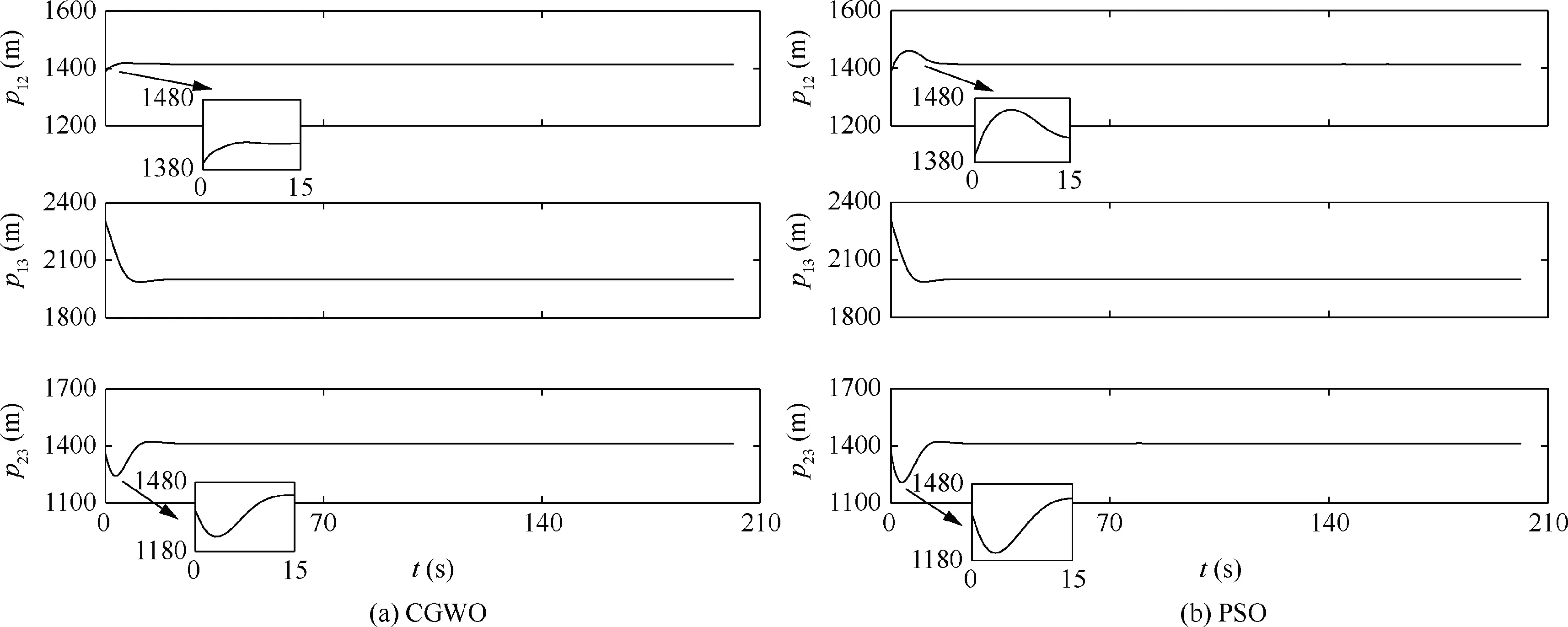
Fig.16 Distances between UAVs by CGWO and PSO.

Fig.17 Angle constraints by CGWO and PSO.

Fig.18 States and control inputs by CGWO and PSO.
Fig.18 shows the states and control inputs of the formation which consist of the linear velocity, acceleration, yaw angle,and angular velocity. The linear velocities of the three UAVs converge to about 158 m/s,134 m/s and 114 m/s as the formation gradually forms the designed shape. The convergence by CGWO is faster than that by PSO. It can be found that as the angular velocities converge to about-0.022 rad/s, the yaw angles vary synchronously. The angular velocities and accelerations remain under control. Fig.19 shows the fitness values of each UAV by CGWO and PSO. The fitness values by CGWO converge faster than those by PSO.
4.2. Example 2 (CGWO-based distributed MPC approach with event-triggered strategy)
In this part, the event-triggered strategy is included into the CGWO-based distributed MPC approach. The reference trajectory and the initial states of the formation are the same as Example 1. Fig.20 presents the flowchart of the designed approach with E2,E3,E4and E7.

Fig.19 Fitness values of each UAV by CGWO and PSO.

Fig.20 Flowchart of CGWO-based distributed MPC approach with E2,E3,E4 and E7.

Fig.21 Illustrations of angle constraints (Example 2).

Table 4 Parameter setting of Case A and Case B.

Fig.22 Ground tracks of UAVs by CGWO (Case A and Case B).
4.2.1. Cases A and B (Different angle constraints)


Fig.23 Tracking errors of formation center by CGWO (Case A and Case B).

Fig.24 Distances between UAVs by CGWO (Case A and Case B).

Fig.25 Angle constraints by CGWO (Case A and Case B).
Fig.22 illustrates the ground tracks of the group of three UAVs. Fig.23 presents tracking errors of the formation center. In Case A, the convergence time of tracking error is about 22 s, which is much faster than about 51 s in Case B.It is due to the different desired states of the three UAVs in the two cases. The tracking errors of formation center are also within the given threshold εp=6 m. Fig.24 presents the distances of the formation, which tend towards the desired ranges much faster in Case A, because the requirement in Case A is easier to meet than that in Case B. Fig.25 shows the angle constraints for the UAV formation which tend towards the desired ranges.
The states and control inputs of the formation are shown in Fig.26. In two cases, it can be found that the variation of yaw angles is synchronous as the angular velocities vary around-0.023 rad/s. The ranges of accelerations and angular velocities remain under limitations. The triggered instants are presented in Fig.27. The FHOCP is not solved continuously in the designed approach. In the beginning, the FHOCP is solved more frequently in Case B than in Case A, because the desired angle constraints are easier to meet in Case A. Table 5 presents the times of event-triggered conditions being satisfied. The numbers decline to about 200 with the event-triggered strategy, while that are about 400 without it. In Case B, the numbers are larger than those in Case A, because the FHOCP is solved more frequently in Case B than in Case A to achieve the demands of mission.

Table 5 Numbers of triggered instants (Case A and Case B).
4.2.2. Cases C and D (Different error thresholds)

Fig.28 illustrates the ground tracks of the three UAVs by CGWO. Fig.29 shows the tracking errors of the formation center. The convergence in Case D is faster than that in case C. It is due to the threshold of tracking error which is lower in Case C than in Case D. The distances in the formation are presented in Fig.30. Fig.31 shows the angle constraints for the UAV formation. The convergence of the angle constraints in Case C is faster,as the requirement in Case D is easier to meet than that in Case C.

Fig.26 States and control inputs by CGWO (Case A and Case B).
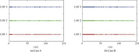
Fig.27 Triggered instants by CGWO (Case A and Case B).

Table 6 Parameter setting of Case C and Case D.

Fig.28 Ground tracks of UAVs by CGWO (Case C and Case D).

Fig.29 Tracking errors of formation center by CGWO (Case C and Case D).

Fig.30 Distances between UAVs by CGWO (Case C and Case D).
Fig.32 shows states and control inputs of the three UAVs.The triggered instants are presented in Fig.33.The solution of FHOCP is more frequent in Case C, as the thresholds in Case C are lower than those in case D. Table 7 shows the times of triggered instants. In Case C, the numbers decrease to about300,and in Case D,the numbers are 125,192 and 141,respectively.The selection of the thresholds is mainly decided by the requirements of mission,and times to solve the FHOCP can be reduced at the expense of control performance.

Table 7 Numbers of triggered instants (Case C and Case D).

Fig.31 Angle constraints by CGWO (Case C and Case D).

Fig.32 States and control inputs by CGWO (Case C and Case D).
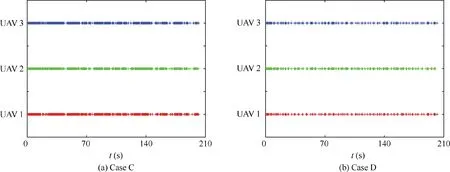
Fig.33 Triggered instants by CGWO (Case C and Case D).

Table 8 Parameters of no-fly zones in Example 3.

Table 9 Parameters of event-triggered conditions in Example 3.

Table 10 Initial states of formation in Example 3.
4.3. Example 3 (CGWO-based distributed MPC approach with no-fly zone constraints)
In this part, the no-fly zone constraints are included to verify the performance of the designed approach. Table 8 presents the parameters of no-fly zones. The coordinates of the center are described by xnf,ynf. The radius and the safe distance of the no-fly zone are represented by R and dsafe=1.5×R,respectively. The parameters of event-triggered conditions are shown in Table 9. Initial states of the formation are presented in Table 10.Fig.34 shows the flowchart of the designed approach with E1,E2,E4,E5,E6and E7as event-triggered conditions.

Fig.34 Flowchart of CGWO-based distributed MPC approach with E1,E2,E4,E5,E6 and E7 as event-triggered conditions.

Fig.35 Ground tracks of UAVs (Example 3).
The no-fly zones are represented by cyan circles and the corresponding safe zones are represented by dotted cyan circles. The whole process can be divided into five phases, i.e.Phase 1 to Phase 5.The straight line is selected as the reference trajectory in Phase 1, Phase 3, and Phase 5. The no-fly zone constraints are included in Phase 2 and Phase 4. As shown in Fig.35,the UAV formation can keep tracking the reference trajectory without violating the two no-fly zone constraints.In Fig.36, the distances converge after about 30 s. It can be also found that the formation is maintained even though no-fly zone constraints are included in the formation control.
The states and control inputs in the formation are shown in Fig.37.In Phase 1,linear velocities converge to about 135 m/s as the formation is gradually formed. Yaw angles converge to about 30° as the angular velocities converge to about 0 rad/s.In Phase 2 and Phase 4, the control inputs of the three UAVs are sometime saturated during formation flight.Linear velocities and the yaw angles change greatly to avoid no-fly zones and maintain the formation. In Phase 3 and Phase 5, linear velocities converge back to about 135 m/s and the yaw angles back to about 30° as the control inputs converge to about 0.
Fig.38 shows the triggered instants for the three UAVs.In Phase 1, the FHOCP is solved frequently at the beginning to form the desired shape of UAV formation. In Phase 2 and Phase 4,the FHOCP is also solved frequently to keep safe distance from the no-fly zone, so that numbers of the triggered instants increase greatly. In Phase 3 and Phase 5, the inputs update frequently at the beginning, as the designed thresholds are transcended frequently while the UAV formation is leaving the no-fly zones. Table 11 presents numbers of the triggered instants. The event-triggered condition E1is only satisfied in Phase 2 and Phase 4,and numbers of event-triggered condition E1are the largest. In Phase 3 and Phase 5, the numbers of event-triggered condition E6&&(E2‖E4‖E5)are larger to keep the formation and track designed reference trajectory.

Fig.37 States and control inputs (Example 3).
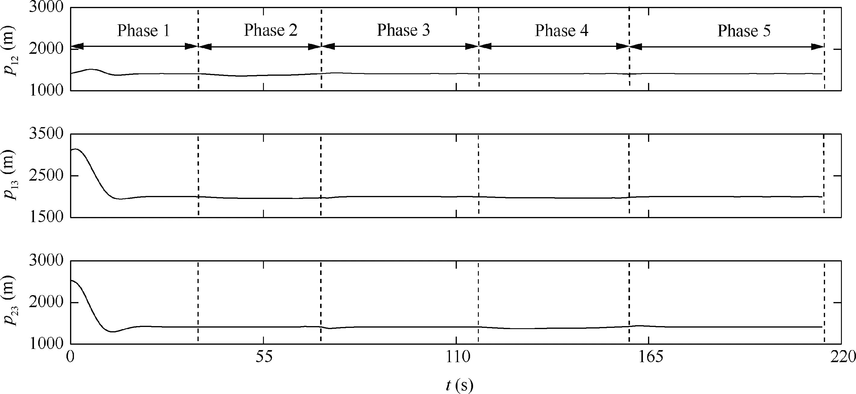
Fig.36 Distances between UAVs (Example 3).

Fig.38 Triggered instants for three UAVs (Example 3).

Table 11 Numbers of triggered instants (with /without event-triggered strategy).
5. Conclusions
A CGWO-based distributed MPC approach is studied to improve the performance of multi-UAV coordination control.The framework of distributed MPC approach is established in consideration of communication limitation.The local FHOCP is solved by the CGWO on the basis of the chaotic initialization as well as chaotic search. It can be found that the CGWO-based distributed MPC shows better performance than traditional PSO-based approach. The formation control and trajectory tracking can be achieved by integrating the distributed cost function into each FHOCP.Considering different constraints and missions, an event-triggered strategy is designed to reduce the computation burden of distributed MPC, which is tested by a series of numerical simulations.The analysis of stability conditions and computation complexity will be studied in the further work.
Acknowledgements
This work was co-supported by the National Natural Science Foundation of China (Nos. 61803009, 61903084), Fundamental Research Funds for the Central Universities of China(No.YWF-20-BJ-J-542), and Aeronautical Science Foundation of China (No. 20175851032).
 CHINESE JOURNAL OF AERONAUTICS2020年11期
- CHINESE JOURNAL OF AERONAUTICS的其它文章
- Event-triggered control for containment maneuvering of second-order MIMO multi-agent systems with unmatched uncertainties and disturbances
- Adaptive level of autonomy for human-UAVs collaborative surveillance using situated fuzzy cognitive maps
- Coactive design of explainable agent-based task planning and deep reinforcement learning for human-UAVs teamwork
- Two-phase guidance law for impact time control under physical constraints
- Adaptive leader–follower formation control for swarms of unmanned aerial vehicles with motion constraints and unknown disturbances
- Optimal video communication strategy for intelligent video analysis in unmanned aerial vehicle applications
