Deformation coordination analysis of CC-RCC combined dam structures under dynamic loads
Bo-wen Shi , Ming-cho Li ,*, Ling-gung Song , Meng-xi Zhng , Yng Shen
a State Key Laboratory of Hydraulic Engineering Simulation and Safety, Tianjin University, Tianjin 300350, China
b Department of Construction Management, University of Houston, Houston, TX 77204, USA
Abstract A combined dam structure using different concrete materials offers many practical benefits.There are several real-world cases where largevolume heterogeneous concrete materials have been used together. From the engineering design standpoint, it is crucial to understand the deformation coordination characteristics and mechanical properties of large-volume heterogeneous concrete, which affect dam safety and stability. In this study, a large dam facility was selected for a case study, and various design schemes of the combined dam structure were developed by changing the configurations of material zoning and material types for a given dam shape. Elastoplastic analysis of the damfoundation-reservoir system for six schemes was carried out under dynamic conditions, in which the concrete damaged plasticity (CDP)model,the Lagrangian finite element formulation,and a surface-to-surface contact model were utilized.To evaluate the mechanical properties of zoning interfaces and coordination characteristics, the vertical distribution of the first principal stress at the longitudinal joint was used as the critical index of deformation coordination control, and the overall deformation and damage characteristics of the dam were also investigated.Through a comparative study of the design schemes, an optimal scheme of the combined dam structure was identified: large-volume roller-compacted concrete (RCC) is recommended for the dam body upstream of the longitudinal joint, and high-volume fly ash conventional concrete(CC)for the dam body downstream of the longitudinal joint.This study provides engineers with a reference basis for combined dam structure design.
© 2020 Hohai University. Production and hosting by Elsevier B.V. This is an open access article under the CC BY-NC-ND license (http://creativecommons.org/licenses/by-nc-nd/4.0/).
Keywords: Combined dam structure; Deformation coordination; CC-RCC; Dynamic response; Finite element simulation; Concrete damaged plasticity (CDP)model
1. Introduction
The roller-compacted concrete (RCC) dam is a relatively new type of dam, which has evolved rapidly in recent years.Compared with traditional concrete dams, the RCC dam has comparable structural strength, and its roller-compaction construction method, similar to earth-rock dam construction,makes field operation more efficient. Different theoretical approaches have been proposed to predict the dam deformation and evaluate the current working state of dams(He et al.,2018;Dou et al.,2019;Yang et al.,2019;Zhang et al.,2019b).However,in practice, it is inevitable that RCC will be used in combination with conventional concrete(CC).For instance,in a project with complex geological conditions and a tight construction schedule,both RCC and CC may be used in dam design and construction. RCC dam construction allows high productivity (Cervera et al., 2000), which can shorten the construction time to make up for delays in foundation treatment. Such methods can effectively alleviate the pressure of the construction schedule for certain dam shapes. However,different material properties and deformation characteristics of CC and RCC do cause structural safety concerns. It has been observed that high deformation gradients tend to occur at the interfaces among large-volume heterogeneous concrete materials (Luo et al., 2016).
Up to now, research on deformation coordination characteristics of high dam structures has been mainly concentrated on interfaces between soil and rockfill materials in rockfill dams(Chen et al.,2016;Liu et al.,2016).Mechanical properties and deformation characteristics of soil materials, rockfill materials,and RCC are quite different. For instance, RCC is typically batched with engineered aggregates and has high cement content. Therefore, the index of deformation coordination control proposed for rockfill dams is not directly applicable to concrete dams. Several recent studies have been conducted specifically to address the coordination and zoning issues for concrete dams. Li et al. (2015) compared the influences of different concrete zoning on seepage control of a dam body.Zhang et al.(2019a) focused on the optimization of temperature control during construction and provided practical guidelines for different scenarios. Zhang et al. (2019c) investigated mechanical properties and isogeometric shape optimization methods of functionally graded structures of a dam. In addition, the Xiangjiaba Dam, which is the first pilot project using highvolume fly ash CC and RCC combined dam construction technology, demonstrated the advantage of rapid RCC construction for certain dam shapes. In this project, material thermodynamic properties were obtained through experiments,and temperature control analysis of typical dam sections was performed using the finite element method. This analysis practically eliminates the safety concerns of combined dam construction in regards to temperature control (Xu, 2015). To further address the stress and deformation issues at the interface of heterogeneous materials, various functional gradient finite element models for RCC gravity dam zoning structures under static conditions were developed, and the impact of elastic modulus changes on the deformation coordination was also analyzed.The results showed that the deformation coordination of the concrete dam zoning structure was satisfactory when only static loads were considered (Li et al., 2018).
With the recent development of hydropower projects in geologically active regions, safety analysis of concrete dams under dynamic loads has attracted increasing levels of attention, so has the analysis of deformation coordination characteristics of concrete dam zoning structures. Thus, many researchers have devoted their time to dynamic load analysis,in which the damping ratio,non-uniformity of the foundation,dam-water dynamic interaction, and damage cracking of dam concrete are taken into account(Wang et al.,2018a;Jin et al.,2019). Nonlinear analysis is required for projects to simulate the dynamic response (Yang et al., 2017). Wang et al. (2019)simulated the earthquake damage to the Pacoima Dam considering the effects of the source mechanism, propagation media, and local site. The results agreed with the actual damage,proving that nonlinear analysis is a promising method for predicting the near-field ground motion at dam sites.Wang et al. (2016) compared the nonlinear dynamic response of a dam to different artificial accelerograms, and the scattered results demonstrated that the spectral characteristics of earthquake accelerograms should be considered. To investigate the nonlinear response of concrete gravity dams under dynamic excitation, the horizontal shake table test and the finite element method (FEM) based on the plastic damage model have been used to analyze the tensile damage.Similar patterns of crack propagations have been observed in physical testing and in digital modeling analysis, thus validating the FEM method (Mridha and Maity, 2014). For dynamic safety analysis of concrete dams,nonlinear numerical models can predict crack initiation and propagation,and have been widely used to evaluate the dynamic resistance of concrete dams.It should be noted that the structural response of linear elastic materials is different from that of nonlinear materials(Oudni and Bouafia,2015).Researchers have also argued that this analysis method requires further research accounting for the effects of joints(Wu et al., 2016; Wang et al., 2018b; Li et al., 2019).
The aforementioned studies primarily focused on the overall deformation characteristics of concrete dams. Little research has been conducted to date to evaluate mechanical properties of zoning interfaces and deformation coordination characteristics of a zoning structure.Large-volume RCC,combined with other materials, for dam construction is gaining popularity. The aim of this study was to analyze different CC-RCC combined dam structures using the modified concrete damaged plasticity(CDP) model (Lubliner et al., 1989; Lee and Fenves, 1998).From the perspective of material and structure coupling control(Li et al.,2017),local and overall deformation characteristics in six different design scenarios were compared.
2. Methodology
Based on a nonlinear contact model and Lagrangian finite element formulation, a numerical framework of dam deformation coordination analysis was established. It includes four parts: the modeling theory, numerical framework, control index,and scheme comparison.First,the proposed framework was validated with an experimental cracking profile of the Koyna Gravity Dam. Then the deformation coordination of a coupled dam-foundation-reservoir system was investigated comprehensively. The vertical distributions of the first principal stress in six different design scenarios were compared,and the overall deformation and damage characteristics under dynamic loads were analyzed. According to the comparisons of the schemes, an optimal scheme of the combined dam structure considering material zoning and material types was identified.The finite element simulation presented in this work was conducted using the general-purpose commercial software ABAQUS/Standard v6.11. The nonlinear contact method and finite element formulation are detailed in this section.
2.1. Contact model
In order to model the behavior of longitudinal joints, a surface-to-surface contact model was used to describe the normal pressure-clearance behavior in this study. Clearance herein is defined as the distance between two contact surfaces.When the clearance is zero, the contact constraint is still in effect so that the two surfaces still maintain their contact,and the contact pressure can take any value.When the two surfaces become separated, the contact pressure drops to zero.
When the two surfaces are in contact, they transmit not only normal stress but also tangential stress. In this study, the Coulomb friction model was used to describe the tangential interaction. When the shear stress reaches the critical threshold, the two planes may slide away from each other.Otherwise, the tangential motion will be zero. The critical threshold value depends on the normal surface contact stress,as shown in Eq. (1):

where μ is the coefficient of friction,pis the contact pressure between two surfaces, and τcritis the critical limiting shear stress.
2.2. Lagrangian finite element formulation
The Lagrangian approach is used here to describe the dynamic interaction of the coupled dam-foundation-reservoir system (Calayir and Dumanoˇglu, 1993; Wilson and Khalvati,1983). In this approach, two nodes are set at the same location on the coupled fluid-solid interface, with one in the fluid domain and the other in the solid structure domain. Displacements of the two nodes at the interface are the same. Fluid or water here is assumed to be linearly elastic, irrotational, and inviscid.For a three-dimensional(3D)fluid element,the stressstrain relationship can be expressed as (Wang et al., 2017):

wherePis the pressure;C11is the bulk modulus of fluid;εvis the volumetric strain; ωx, ωy, and ωzare the rigid body rotations with respect to the Cartesian axesx,y, andz, respectively;Px,Py,andPzare the corresponding rotational stresses;andC22,C33, andC44are the constraint parameters.
2.3.Modelvalidationwithdam-foundation-reservoirsystem
Based on the results of trial calculation, the parameter values of the CDP model were selected: the dilation angle ψ = 30°, the eccentricitym= 0.1, the ratio of initial equibiaxial compressive yield stress to initial uniaxial compressive yield stress αf= 1.16, the ratio of the second stress invariant on the tensile meridian to that on the compressive meridianKc= 0.666 7, and the viscosity parameter μv= 0.002 5.
The formulas in theCode for Design of Concrete Structures in China(GB 50010-2010) were used to calculate the constitutive relation, which fit well with the curve obtained from the model test, proving the reliability of the selected model parameters,as well as a general capability of the CDP model for modeling concrete under dynamic loads.
The Koyna Gravity Dam, located at 17°23′N, 73°45′E in India, was selected for validation of the reliability of the proposed numerical framework.The Koyna Gravity Dam was seriously damaged in an earthquake in 1967, and its design and operational data were well documented for further investigation (Chopra and Chakrabarti, 1972). Therefore, this dam has been used as a classic case for dynamic analysis of gravity dams. In this study, the dam structure was modeled with a monolithic 3D finite element model.This model allows us to numerically analyze the dam's dynamic response to actual earthquakes. In order to be consistent with the seismic input in the actual model test (Mridha and Maity, 2014), only the horizontal measured seismic waves were considered. The material parameters of the CDP model for the Koyna Gravity Dam are listed in Table 1. Seismic waves were assumed to originate from the bottom of a massless foundation;water was assumed to be linearly elastic, irrotational, and inviscid; and the foundation was assumed to be purely elastic.The Rayleigh damping method with a 5%damping ratio was used to account for the energy dissipation problem of the dam-foundationreservoir coupled system.
Various loads were considered in this study, including the hydrostatic pressure, hydrodynamic pressure, gravity, and seismic loads.The hydrostatic pressure and gravity were taken as initial input values for structural analysis. For model initialization, nodal normal displacements on the truncated boundary of the reservoir and foundation were constrained,and in particular, the bottom boundary of the foundation was fully constrained. However, after the static analysis, all displacement constraints were removed and seismic loads were input from the base of massless foundation.Fig.1 shows the final cracking profile of the Koyna Gravity Dam obtained from the quasi-3D finite element simulation. The comparison of the simulated results with that obtained from the shake table tests in Mridha and Maity (2014) reveals that the numerical cracking profile is fairly consistent with the actual observed seismic damage.Using the Koyna Gravity Dam as a test case,this validation study indicates that the quasi-3D modeling can be used to serve as a candidate method for simulating the dynamic response of a dam structure and damage evolution under dynamic loads.

Table 1 Material properties of Koyna Dam-foundation-reservoir model.
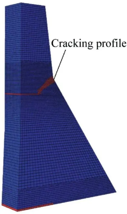
Fig.1.Three-dimensional finite element simulated results of cracking profile of Koyna Dam.
3. Case study
The case study focused on the deformation coordination of a real CC-RCC combined dam structure under dynamic loads,which is located in southwestern China.In this study,3D finite element analysis of a typical sluice section was carried out.To account for the effects of material zoning and material properties, six design schemes were developed. According to the comparisons of the schemes, a reference basis could be provided for the combined dam structure design.
3.1. Parameters and model of actual dam-foundationreservoir system
The height of the dam section is 144 m. Fig. 2 shows the finite element discretization of the dam.The mesh is relatively fine, consisting of 55 172 elements and 107 028 nodes. The downstream direction is thex-axis,the direction along the axis of the dam is they-axis,and the vertical direction is thez-axis.Due to the lack of documented seismic data near the dam area,seismic records at a similar site(El Centro seismic waves from Neumann (1941)) were used to provide dynamic load data.According to the design peak acceleration of 0.12g,where the gravity dam is located, the original data were scaled, and the result is shown in Fig.3.This study assumed that the clearance of the longitudinal joint was 4 mm at the dam top, and it gradually dropped to zero at the ground level.
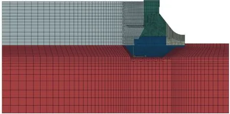
Fig. 2. Finite element model of typical sluice section.
Based on the design data, the material properties for the dam concrete are as follows: the mass density is 2 400 kg/m3and Poisson's ratio is 0.167.In order to consider the rate effect under dynamic loads, the material parameters were adjusted according to theCode for Seismic Design of Hydraulic Structures of Hydropower Projects in China(NB 35047-2015). Dynamic material parameters for the actual gravity dam-foundation-reservoir system are listed in Table 2,including those for RCC,II CC,I-2 CC,CC with 35%fly ash,and CC with 20%fly ash.In particular,II CC and I-2 CC refer to two special high-volume fly ash conventional concrete types.
3.2. Results and discussion
3.2.1. Influence of material zoning
Nonlinear dynamic analysis was performed to investigate the deformation coordination characteristics of the combined dam structure,in which the effect of material zoning was taken into account. With the actual sluice section considered as the base scheme, three additional design schemes (schemes 1, 2,and 3, shown in Fig. 4) were introduced for comparative analysis.
Fig. 5 shows the variation of streamwise displacement of the dam crest in the base scheme with respect to the foundation and the crest displacement differences between the comparative schemes (schemes 1 through 3) and the base scheme. All four schemes shared a similar change trend of the relative displacement of the dam crest. Furthermore,compared with the static analysis, the maximum crest displacements in the base scheme and schemes 1, 2, and 3 obtained from the nonlinear dynamic analysis were increased by 30.7 mm, 31.1 mm, 29.2 mm, and 28.5 mm,respectively.
In the dynamic analysis, similar opening and closing deformations occurred at longitudinal joints. Fig. 6 shows the trend of longitudinal joint opening in the base scheme and the differences of longitudinal opening between the comparative schemes and the base scheme. The variations of the longitudinal joint openings in schemes 2 and 3 were similar. In the static analysis, the longitudinal joint openings in the four schemes were all close to 0, which indicated a complete closure. Compared with the results of the static analysis, the maximum longitudinal joint openings in the base scheme and schemes 1, 2, and 3 obtained from the nonlinear dynamic analysis were increased by 1.02 mm, 1.11 mm, 0.80 mm, and 0.79 mm, respectively.
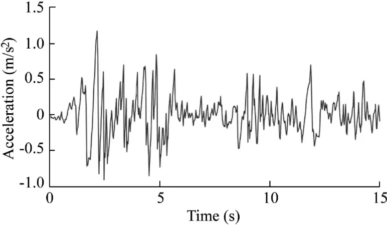
Fig. 3. Scaled seismic sequence.

Table 2 Dynamic material properties of actual dam-foundation-reservoir model.
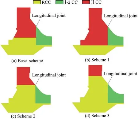
Fig. 4. Structural design of concrete zoning for combined dam structures.
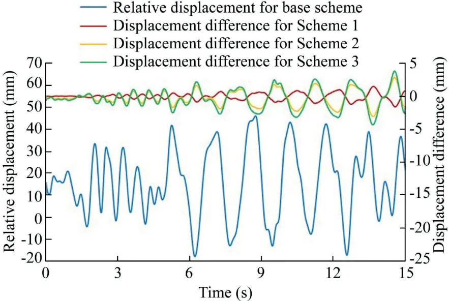
Fig. 5. Relative displacement of dam crest in base scheme and crest displacement differences between comparative schemes and base scheme.

Fig. 6. Longitudinal joint opening in base scheme and differences of longitudinal joint opening between comparative schemes and base scheme.
Overall, the damage distributions for these four schemes were similar. The tensile damage value of the dam body was obtained by means of the calculated stress with FEM and displayed with the software ABAQUS. As shown in Fig. 7,damage mainly occurred in the following regions: the dam heel, the upstream slope, and the bottom of the longitudinal joint. The overall damage of the dam was not severe. Moreover, the dam heel did not crack through the curtain, thus would have no impact on the overall stability. The damage ranges at the dam heel decreased with the increase of RCC volume, as shown in Fig. 8.
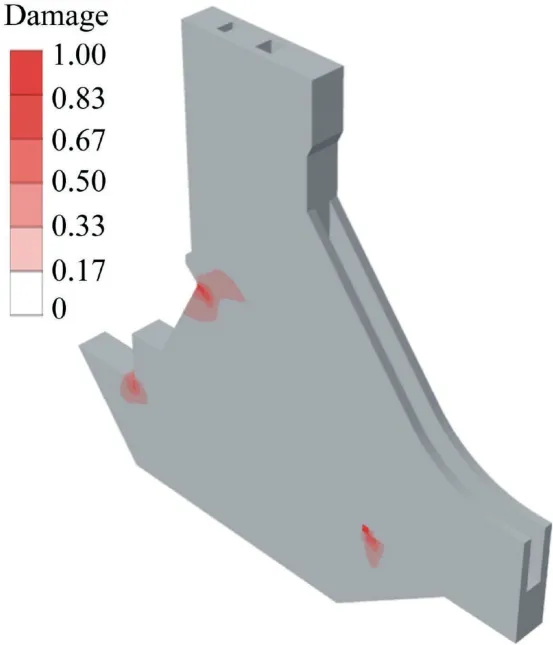
Fig. 7. Final damage profile of Scheme 3.
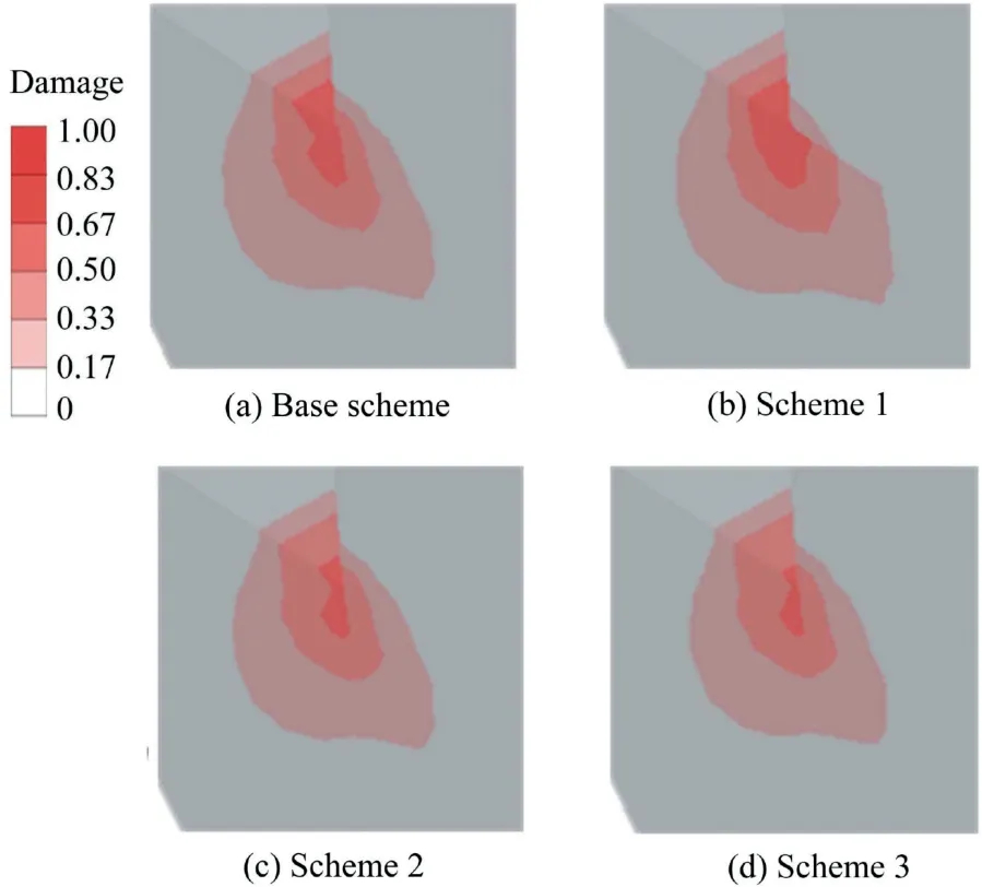
Fig.8.Final damage profiles at dam heel in base scheme and schemes 1 through 3.
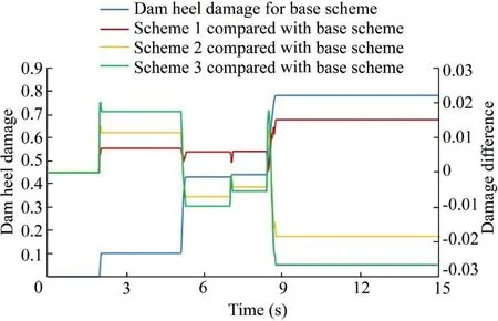
Fig. 9. Cumulative process of dam heel damage in base scheme and comparison with those in schemes 1 through 3.
The dam heel damage is a key issue for dam safety.Fig.9 shows the cumulative process of tensile damage at the dam heel.The left vertical axis represents the dam heel damage in the base scheme, and the right vertical axis represents the difference of damage between the base scheme and a comparative scheme. Due to material zoning, a comparative scheme with relatively greater initial damage has less final damage. The final damages in schemes 1, 2, and 3 were 102%, 98%, and 97% of that in the base scheme,respectively.
In the dynamic analysis, the stress of the dam body fluctuated around the value generated in the static analysis.For the above-mentioned schemes, the vertical distributions of the first principal stress at various elevations downstream of the longitudinal joint are illustrated in Fig. 10. Note that the black dotted line indicates the elevation of the heterogeneous concrete interface in the base scheme.It can be seen that the base scheme experienced the problem of local tensile stress concentration because of the uncoordinated deformation occurring at the horizontal interface between RCC and CC. However, there was no stress concentration problem in the three comparative schemes, since homogenous concrete was used upstream of the longitudinal joint. It was also found that the lower halves of the upper limit stress curves are close to straight lines for schemes 1 through 3.Compared with the maximum first principal stress in the base scheme at the elevation of the dividing line, the values in schemes 1, 2,and 3 were reduced by 9%, 15%, and 16%, respectively. In addition, the lower limits of the first principal stresses in the four schemes were close to one another.
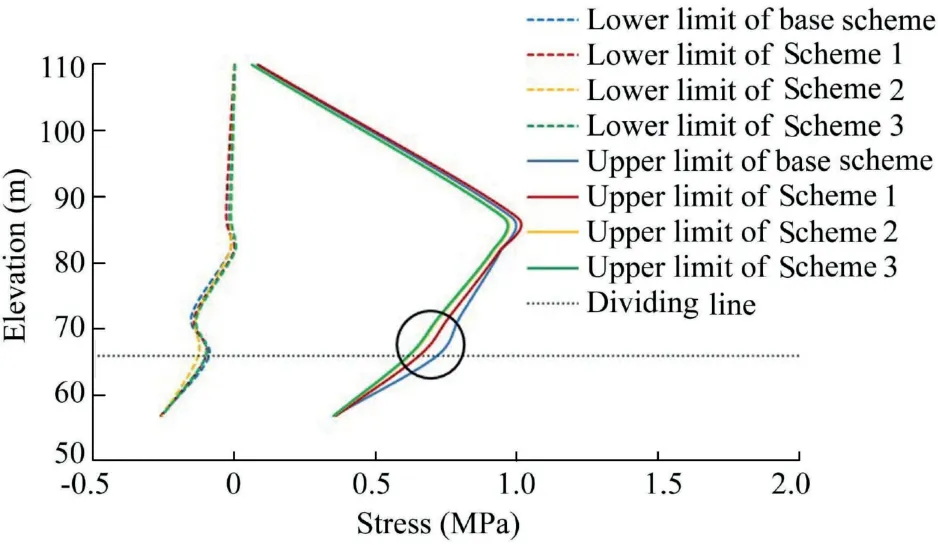
Fig. 10. Vertical distributions of first principal stress downstream of longitudinal joint in base scheme and schemes 1 through 3.
In summary, the advantages of large-volume high-elasticity RCC in dam construction are clear. In the dynamic analysis,compared to the base scheme,the dam crest peak displacement was reduced by 7%, the peak of the longitudinal joint opening was reduced by 23%, and the final dam heel damage was reduced by 3%. Scheme 3 effectively controlled the overall dynamic response and ensured the dam operation safety.Moreover, this scheme also considered the deformation coordination characteristics of heterogeneous concrete. The deformation at the longitudinal joint was coordinated,no local stress concentration problem occurred,and the maximum tensile stress was relatively small.
3.2.2. Influence of material properties
Based on the analysis results above,the effects of different materials on the deformation coordination characteristics were explored.Using Scheme 3 as the reference scheme,schemes 4 and 5 were introduced for comparison purposes, as shown in Fig. 11.
Fig.12 shows the crest displacement differences between the two comparative schemes (schemes 4 and 5) and Scheme 3.With the increase of dynamic load time, the displacement difference between schemes increased gradually. Compared with the maximum crest displacements in the static analysis, the values in schemes 3, 4, and 5 obtained from the dynamic analysis were increased by 28.5 mm, 28.3 mm, and 27.6 mm,respectively.
Fig.13 shows the longitudinal joint opening differences between the two comparative schemes and Scheme 3.In the static analysis, the longitudinal joint openings in the three schemes were all close to 0,indicating a complete closure.Compared with the results of the static analysis,the maximum longitudinal joint openings in schemes 3, 4, and 5 obtained from the dynamic analysis were increased by 0.79 mm, 0.83 mm, and 0.90 mm,respectively.
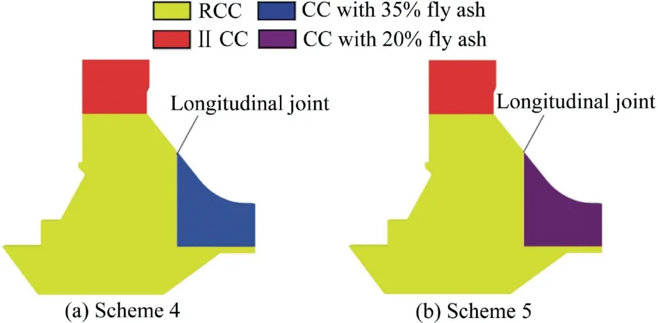
Fig. 11. Structural design of different materials for combined dam structures.
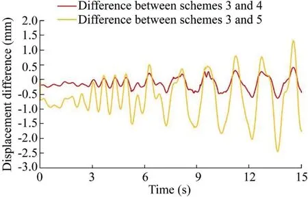
Fig.12.Crest displacement differences between comparative schemes and Scheme 3.
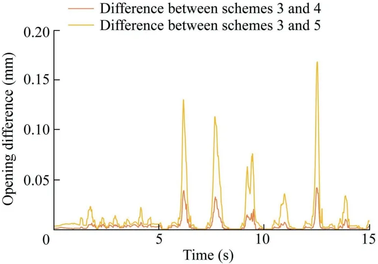
Fig. 13. Differences of longitudinal joint opening between comparative schemes and Scheme 3.
Overall,the damage distributions in the three schemes were similar. With increasing concrete material strength toward the bottom of a dam, the level of damage at the dam heel was reduced more significantly,as shown in Fig.14.The dam heel did not crack through the curtain, and the level of damage could be considered minor, meaning that the structure was unlikely to fail. Fig. 15 shows the cumulative process of tensile damage at the dam heel. The cumulative damages in schemes 4 and 5 were 99% and 94% of that in Scheme 3,respectively, which is considered favorable from dam safety and stability standpoints.
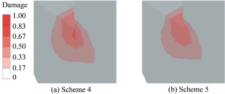
Fig. 14. Final damage profiles at dam heel in schemes 4 and 5.
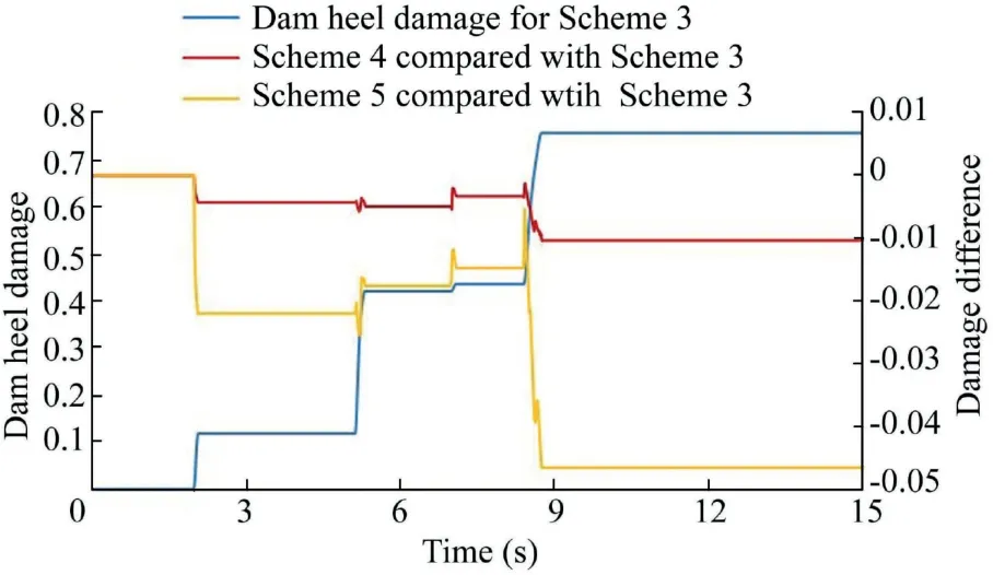
Fig. 15. Cumulative process of dam heel damage in Scheme 3 and comparison with those in schemes 4 and 5.
Thevertical distributions of the first principal stress at various elevations downstream of the longitudinal joint in schemes 3,4,and 5 are illustrated in Fig.16.It can also be seen that the lower halves of the upper limit stress curves of schemes 4 and 5 are close to straight lines, indicating that there was no problem regarding local tensile stress concentration. This observation shows that the stress concentration occurs at the heterogeneous concrete interface,which is consistent with that discussed in the previous section. Compared with the maximum first principal stress in Scheme 3 at the elevation of 87 m,thevalues in schemes 4 and 5 were increased by 12%and 38%,respectively.The low limit of the first principal stress in Scheme 3 was slightly less than those in the two alternative schemes,but they were all much less than the compressive strength of concrete materials.
3.2.3. Scheme comparison
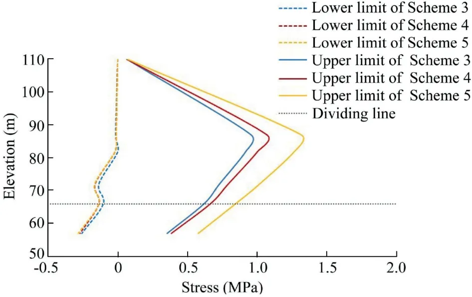
Fig. 16. Vertical distributions of first principal stress downstream of longitudinal joint in schemes 3 through 5.

Table 3 Index differences between comparative schemes and Scheme 3.
Table 3 shows the four indices of schemes 4 and 5,compared with those in Scheme 3.The use of CC with small-volume fly ash is beneficial since it increases the overall stiffness of the dam and weakens the dynamic response of the dam.However,when the amount of fly ash in the longitudinal joint is decreased, the difference between the elastic moduli of the concrete on both sides increases,leading to the problem of uncoordinated deformation. With the decrease of the amount of fly ash, the longitudinal joint opening increases, and the first principal stress at the longitudinal joint also increases,which is not conducive to dam safety and stability. Therefore, from the perspective of deformation coordination,it is recommended to choose Scheme 3, i.e., selecting large-volume RCC to cast the dam body upstream of the longitudinal joint,and selecting I-2 CC to cast the dam body downstream of the longitudinal joint.
4. Conclusions
In this study, the CDP model was used to analyze the dynamic response of a combined dam structure in different schemes and explore its deformation characteristics through case studies. The vertical distributions of the first principal stress at various elevations downstream of the longitudinal joint were selected as local deformation characteristics.Considering the overall deformation and damage characteristics,the following important factors were taken into account in this study:crest displacement,longitudinal joint opening,dam heel damage, and damage distribution. Based on a comprehensive comparison of local and overall deformation characteristics,the main conclusions of the study can be summarized as follows:
(1) Stress concentration occurs at the interface of heterogeneous concrete zones upstream of the longitudinal joint, which indicates the uncoordinated deformation problem. We recommend using homogenous concrete to cast the dam body upstream of the longitudinal joint. Such a scheme can reduce the maximum tensile stress downstream of the longitudinal joint, which is beneficial to the stability of the dam.
(2)Based on the comparison of different ash contents of CC,we recommend choosing high-volume fly ash CC to cast the dam body downstream of the longitudinal joint, which can decrease the tensile stress downstream of the longitudinal joint.
(3) According to the structural deformation coordination characteristics, Scheme 3 shows a stronger performance in terms of the safe and stable operation of the concrete gravity dam.That is to say,large-volume RCC is recommended for the dam body upstream of the longitudinal joint, and I-2 CC is suggested for the dam body downstream of the longitudinal joint.
It is important to note that the actual construction scheme of a combined dam structure needs further consideration.In regard to the comparisons of the schemes mentioned above, only the deformation characteristics were taken into consideration. It is necessary to take more factors into consideration, such as seepage analysis,material limitation,and construction capability,so as to provide more comprehensive references for combined dam structure construction.
Declaration of competing interest
The authors declare no conflicts of interest.
 Water Science and Engineering2020年2期
- Water Science and Engineering的其它文章
- Hydrological response to climate change and human activities:A case studyof Taihu Basin,China
- Possibilities of urban flood reduction through distributed-scale rainwater harvesting
- Toxic response of aquatic organisms to guide application of artemisinin sustained-release granule algaecide
- Effects of water application intensity of micro-sprinkler irrigation and soil salinity on environment of coastal saline soils
- Responses of river bed evolution to flow-sediment process changes after Three Gorges Project in middle Yangtze River: A case study of Yaojian reach
- PIV analysis and high-speed photographic observation of cavitating flow field behind circular multi-orifice plates
