Development of microstructural inhomogeneity in multi-pass flow forming of TA15 alloy cylindrical parts
Xianxian WANG, Pengfei GAO, Mei ZHAN, Ke YANG, Yunda DONG,Yukun LI
State Key Laboratory of Solidification Processing, Shaanxi Key Laboratory of High-Performance Precision Forming Technology and Equipment, School of Materials Science and Engineering, Northwestern Polytechnical University, Xi’an 710072, China
KEYWORDS Deformation history;Microstructural inhomogeneity;Multi-pass flow forming;TA15 alloy cylindrical parts;Vickers hardness
Abstract Revealing the development of microstructural inhomogeneity in the multi-pass flow forming of titanium alloy components is of great significance to the microstructure control and property tailoring. To this end, the microstructural inhomogeneity of TA15 alloy spun cylindrical parts was analyzed based on the deformation history. The results indicate that the material underwent significant compressive strain in the normal direction (ND), tension strain in the rolling and circumferential directions (RD and CD), while tension strain in the CD is slightly small due to the limited material flow in this direction. These strain characteristics make the microstructure, especially the primary α (αp), present different morphologies in the different planes of the part. Meanwhile,the combined effects of inhomogeneous deformation and temperature distribution in the ND also cause the inhomogeneity of microstructure morphology and parameters in this direction.Quantitative analyses show that with the forming pass increasing, the aspect ratio of αp increases most in the normal-rolling plane, then in the normal-circumferential plane and least in the circumferential-rolling plane, whereas αp content decreases in an opposite trend. Along the ND,the aspect ratio and content of αp is relatively high in the outer and inner surface areas but lowest in the central area, and these inhomogeneous characteristics can be gradually diminished with the forming pass increasing. Furthermore, the variation of hardness inhomogeneity factor indicates that a four-pass forming with the total reduction ratio of 63% could obtain a homogenous microstructure along the ND of the TA15 alloy spun cylindrical part.
1. Introduction
Titanium cylindrical parts are often served as key loading bearing structures in aviation and aerospace fields due to their superior mechanical properties, such as high specific strength,good thermal stability and excellent corrosion resistance.1-4In view of the application of titanium cylindrical parts in severe conditions, it is very critical to assure the uniformity and reliability of mechanical properties during their forming process.It is well known that the mechanical properties are essentially determined by the microstructure. Moreover, the microstructural homogeneity plays great roles in the reliability of mechanical performance.5-8Therefore, it is crucial to understand the microstructure and its homogeneity for tailoring the mechanical properties of titanium cylindrical parts.
Generally, titanium cylindrical parts are processed by the multi-pass flow forming (tube spinning) at elevated temperature due to its advantages of low forming force,simple tooling and high material utilization.9,10In this process, a continuous and localized force is applied to a billet rotating together with mandrel by one or more rollers feeding axially to reduce the thickness of billet. The stress and strain rate states in this process have been explored by Xu et al.11based on a finite element(FE) model. Their simulation results revealed the features of inhomogeneous deformation in various regions of the cylindrical part along the normal, rolling and circumferential directions (ND, RD and CD), respectively. Roy et al.12found that the equivalent plastic strain is higher at the inner and outer surfaces but lowest at the central of the spun component.Since the magnitude of strain greatly influences the changes of grain size and shape during hot deformation, the inhomogeneous deformation in the flow forming process may produce different grain morphologies among different planes and inhomogeneous microstructure along the thickness direction of the cylindrical parts.13Additionally, the microstructure evolution of titanium alloy is very complex during hot working, which includes the changes of primary α (αp), lamellar α (αl), secondary α (αs) and β phase.14,15This may intensify the microstructural inhomogeneity of titanium components.Therefore, revealing the origin and evolution of inhomogeneous microstructure during flow forming process is of great significance to tailoring the mechanical properties of titanium cylindrical parts.
To date, some investigations have been carried out on the microstructure evolution in the multi-pass flow forming at elevated temperature. Wang et al.2analyzed the microstructure evolution and its mechanism of Ti-6Al-2Zr-1Mo-1V alloy spun cylindrical parts. Their results show that elongated αpalong RD and basal {0002} texture can be formed after flow forming. The αpgrains can be refined by continuous dynamic recrystallization (CDRX) and deformation induced localized shear(DILS).Zhang et al.13found that in the hot flow forming of AZ31B magnesium alloy, the c-axes of most grains are approximately parallel to the RD and best mechanical properties can be achieved due to grain refinement and texture strengthen. Chen et al.16revealed that the dislocation slip is the main deformation mechanism and the recrystallization of αpis the major softening mechanism in the hot flow forming of TA15 alloy. Shan et al.17explored the correlation of the microstructure and texture with deformation history in the flow forming of TA15 alloy. Their results indicate that compression deformation in the tangent plane of the tube leads to the generation of distorted αpand significant compression in the ND causes the formation of basal texture. Xu et al.18focused on revealing the effect of deformation on the mechanical properties of TA15 alloy spun cylindrical parts. It can be concluded that the previous researches paid much attention to the deformation mechanism, grain refinement and texture evolution during flow forming.However,the formation mechanism for the microstructural inhomogeneity and the development of inhomogeneous microstructural morphology and parameters in this process haven’t been revealed yet. Therefore,it is necessary to reveal the correlations among the deformation history,microstructural homogeneities and mechanical response to control the microstructure and properties of the titanium spun cylindrical parts.
The objective of the present study is to clarify the formation mechanism and the development of microstructural inhomogeneity in the multi-pass flow forming of TA15 alloy cylindrical parts. By analyzing the effects of deformation history(strain path)on microstructural parameters,the origin of inhomogeneous microstructure in different planes and its development along the ND are revealed.In addition,the influences of inhomogeneous microstructure on mechanical properties of the cylindrical part are evaluated.
2. Simulation and experimental details
2.1. FE model of multi-pass backward flow forming
Since the microstructure evolution is greatly dependent on deformation, it is essential to understand the deformation characteristics of the flow forming process first to reveal the development of microstructural inhomogeneity. For this purpose, an FE model for the multi-pass backward flow forming of TA15 alloy at elevated temperature is established based on ABAQUS/Explicit platform, as shown in Fig. 1. Here,the material flow direction is opposite to that of roller traversing, and the 1, 2 and 3 axes corresponds to the ND, CD and RD of the cylindrical part, respectively.
In the FE model,the effects of deformation heat,heat conduction and radiation are considered.The mandrel and rollers are assumed as analytical rigid body, and the billet is considered as deformable body meshed by an 8 node hexahedron thermal coupling elements. The constitutive relationship implant into the FE model is based on the stress strain curves of TA15 alloy displayed in the Ref. 19. The mass scaling of 3000 and mesh size of 1.5 mm are adopted to ensure the efficiency and accuracy in simulation.20Meanwhile, the coupling constraint is adopted to limit the axial displacement of the billet, and the Arbitrary Lagrange Euler (ALE) adaptive grid technique is employed to avoid the distortion of the mesh during forming. In this model, the billet is underwent five-pass flow forming by three rollers with no stagger,and the thickness reduction in each pass is 3 mm. Therefore, the total thickness reduction ratio of each pass is 15.79%, 31.58%, 47.37%,63.16%,78.95%,respectively. Other main processing parameters are shown in Table 1.
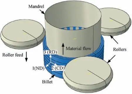
Fig. 1 Finite element model for multi-pass backward flow forming.
To evaluate the reliability of the FE model, the energy distribution of the model is obtained, as shown in Fig. 2(a). It is found that the ratio of kinetic energy to internal energy is less than 5% during the most stage of the process, which suggests that the inertial effect due to the mass scaling do not significantly affect the simulation results.21,22Additionally,the thickness of the part obtained from the FE model is compared with the experimental results, as shown in Fig. 2(b). The maximum error of 7.8% between the simulation and experimental thickness also verifies the reliability of the FE model.
2.2. Flow forming experiment design
The multi-pass backward flow forming experiments were performed on a HO-018 CNC spinning machine with three rollers in the same axial plane. The initial billet is a TA15 alloy ring.The chemical compositions of this alloy are as follows: Al:6.62; Mo: 1.72; V: 2.23; Zr: 2.26; Fe: 0.03 and Ti balance.The measured β-transus temperature of the alloy is 998°C.The geometry parameters of the ring billet and processing parameters of the process are the same as those in simulation(Table 1).Before flow forming,the mandrel and billet was preheated to 400°C and 800°C, respectively. During flow forming, a stroke of each pass was decreased for the convenience of microstructure observation, as shown in Fig. 3. After processing,the spun part was annealed at 750°C for 2 h followed by air cooling to ambient temperature to eliminate its internal stress.Fig.4 Contouring images of strain components at 1/2 process of second pass backward flow forming.
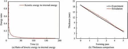
Fig. 2 Reliability evaluation of FE model.
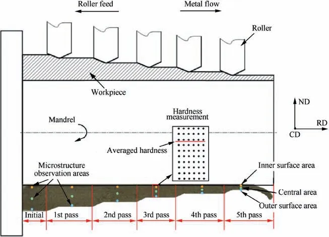
Fig. 3 Schematic of multi-pass backward flow forming.
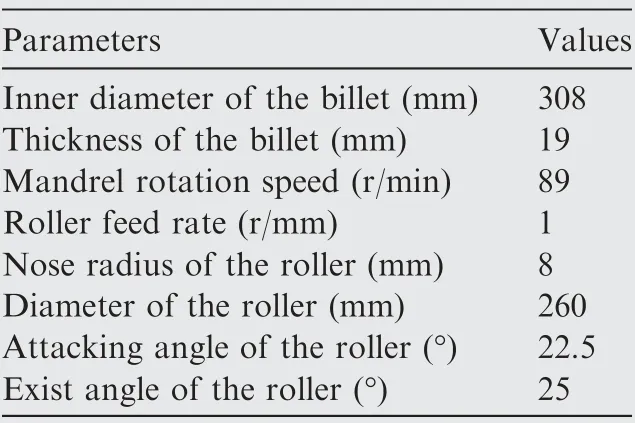
Table 1 Main parameters during flow forming process.
2.3. Microstructure observation and hardness tests
For microstructure observation, metallographic specimens were extracted in the central area of normal-rolling (N-R),normal-circumferential (N-C), circumferential-rolling (C-R)planes of the spun cylindrical part, as shown in Fig. 3. Meanwhile, the specimens near the outer surface, central and inner surface regions of the part were also extracted to characterize the microstructure evolution along the ND.All specimens were prepared by grinding,polishing and chemical etching in a solution of 15% HNO3+5% HF+80% H2O for 10 s. The quantitative microstructural parameters were measured by Image Pro-Plus software. In addition, Vickers hardness tests were carried out on a THV-1MD machine at a load 200 g for 10 s in N-R planes. Along the ND of each sample, the hardness of 10 equidistant positions was measured, as shown in Fig. 3. Meanwhile, the hardness was tested 6 times along the RD, and the mean value was taken as the result.
3. Results and discussion
3.1.Deformation characteristics during the multi-pass backward flow forming
According to the developed FE model, the deformation characteristics (strain components) in the flow forming process were obtained, as shown in Fig. 4. In addition, the evolution of strain components at a certain node with forming pass increasing was also analyzed. Here, the middle position of cylindrical part in the ND (node 3 in Fig. 4)is taken as example, whose evolution of strain components is shown in Fig. 5.In these figures, it is found the most significant compressive strain produces in the ND (LE11), and there is tensile strain in the CD (LE22) and RD (LE33) to accommodate the compressive deformation. However, the LE22 is relatively small due to the limitation of material flow along the CD. With the forming pass increasing, the three nominal strain components gradually accumulate. Meanwhile, there is significant shear strain in N-C plane (LE12), which is caused by the friction between mandrel and rollers. This shear strain increases rapidly before the fourth pass but keeps steady in the following stages. Since the material will flow to the opposite direction when it locates ahead and behind the roller, the shear strain in the N-R plane (LE13) and C-R plane (LE23) fluctuates obviously when the material is deformed, and these components hardly accumulate at each forming pass, especially for the LE13. It is also noted that all strain components are inhomogeneous along the ND (Fig. 4), which would result in the inhomogeneous microstructure in this process.

To analyze the strain variation along the ND,the deviation degree of strain(DDS)from the inner surface to the outer surface of the cylindrical part is defined as the following equation:where,i=1,2,...,5 represents the node number along the ND path sequentially, as shown in Fig. 4. Considering that the LE11 is the most significant strain component,the DDS of this component is obtained,as shown in Fig.6.As is seen,the DDS gradually increases from the inner surface to the outer surface in each pass,and their values decrease rapidly with the increase of forming pass.From the first pass to the fifth pass,the maximum DDS decreases from 58.55% to 15.49%. These results suggest that the deformation homogeneity in ND can be greatly improved with the forming pass increasing.
3.2. Microstructural inhomogeneity in different planes
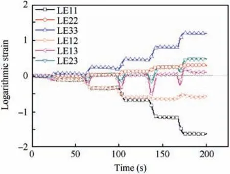
Fig. 5 Evolution of strain components with forming pass increasing.
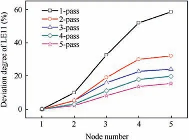
Fig. 6 Deviation degree of LE11 along ND of spun cylindrical part with forming pass increasing.
Fig.7 displays the microstructure in the central area of the NR, N-C, C-R planes of the initial billet and spun cylindrical part. As can be seen, the microstructure of the initial billet is a typical bi-modal microstructure, which consists of αpwithin transformed β (βt). The average diameter of the αpis approximately 10 μm,and the slender αsin βtis with the length about 2 ~4 μm. After the first pass, the morphology of αpslightly elongates along the RD,as shown in Fig.7(b1)and(b3).Additionally,some of αsbecome short and distribute like a necklace around the αp, which suggests that αsis refined by the DRX.After the third pass,ellipse-shaped morphology of αpbecomes obvious,as shown in Fig.7(c1-c3).The αpis compressed along the ND and elongated along the RD and CD,while its elongation along the RD is more significant, which corresponds to the compressive strain in the ND and tension strain in the RD and CD(Fig.5).At the same time,the αscan be achieved a great degree of refinement. However, it is noted that the grain size of αpgets larger in the C-R plane compared with that in the N-R,N-C planes during flow forming process.After the fifth pass,both the changes in the morphology of αpand grain refinement degree of αsget greater,as shown in Fig.7(d1-d3).In this case, the large αpmorphology in the C-R plane is observed more obviously.
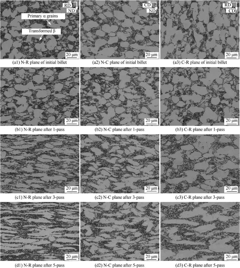
Fig. 7 Microstructure evolution in different planes of spun cylindrical part.
The quantitative analysis of microstructure in different planes is characterized by the aspect ratio (the ratio of major axis to minor axis)and the content of αp,as presented in Fig.8.Here, the grain with area larger than 10 μm2is considered as αp.In Fig.8(a),the aspect ratio of αpin all planes of the initial billet is approximately 2, which suggests that the initial microstructure of the billet is relatively homogenous. With the increase of the flow forming pass, the aspect ratio of αpin the N-R plane increases sharply, and its value is high up to 7 after five-pass flow forming. The aspect ratio in the N-C and C-R planes also increases. However, its value in the C-R plane is slightly lower than that in the N-C plane. In Fig. 8(b), the content of αppresents an opposite trend to the aspect ratio in the three planes, i.e.,αpcontent decreases in the order of the N-R, N-C, C-R planes. With deformation increasing,the generated plastic deformation heat will enhance the forming temperature slightly. Since the αpcontent is inversely proportional to the forming temperature,23its value in all planes decreases with the increase of forming pass.
To reveal the formation mechanism of different αpmorphologies in three planes,it is necessary to understand the relationship between the macroscopic deformation and local deformation of αpgrain. Since the change of length caused by shear strain is the higher-order infinitesimal during macroscopic deformation,24the influence of nominal strain on grain morphology is only considered in the present study.However,it cannot be denied that the shear strain plays important roles in microstructure mechanism,i.e.,grain refinement and texture evolution.25The local strain of αpgrain is approximately estimated by the change of average axis length after each pass.26The detailed calculation equations are as follows:

where,εNi,εCiand εRimeans the average local strain of αpgrain in the ND,CD and RD after the ith forming pass,respectively.LNi, LCiand LRirepresents the average axis length of αpgrain in these directions after the ith forming pass,respectively.Correspondingly,LN0,LC0and LR0is the average axis length of αpgrain in these directions of the initial billet, respectively.
Based on the Eqs. (2)-(4) and Fig. 5, the average local strain components of αpand the nominal strain components of plastic deformation in the ND,CD and RD after each pass are obtained, as shown in Fig. 9. As can be seen, the absolute values of nominal strain components in macroscopic are much higher than those of local strain components of αpin all directions,while these two types of strain present the similar trends in the same directions with the flow forming pass increasing.These facts indicate that different αpmorphologies in three planes of the titanium spun cylindrical part origin from the difference in nominal strain components during flow forming.Additionally, it is observed that the difference between these two types of strain gradually increases with the forming pass increasing, which suggests the inhomogeneous characteristics can not be reduced due to the special deformation state in the flow forming process. The reason for this phenomenon is that with the small amount of deformation, the deformation is mainly undertaken by αp,27promoting the morphology development of αp. As the forming pass increases, the plastic deformation not only accommodates the αpmorphology evolution, but also facilitates the αpand αsrecrystallization, αsglobularization and texture evolution,2thus leading to the significant difference between them.
3.3.Microstructural inhomogeneity along the thickness direction
Since the inhomogeneous strain state exists along the thickness direction, i.e., ND (Fig. 4), the microstructure in the different areas along this direction in N-R plane is mainly observed, as shown in Fig. 10. As can be seen, the initial microstructure of the billet is relatively homogenous along the ND.After the first flow forming pass, an obvious difference in microstructure occurs along this direction.In the outer surface area,the elongated αpand tiny αswith equiaxed shape are observed, as shown in Fig.10(b1).However,there is no remarkable change in grain morphology in the central area of the part (Fig. 10(b2)). In the inner surface area (Fig. 10(b3)), the content of αpincreases visually and a large amount of αpwith barshaped appears. As mentioned above, αpcontent is related to the temperature variation. The low temperature of mandrel promotes the formation of α phase in the inner surface area.When the billet is spun after the third pass, microstructure morphologies of αpin all areas change obviously, as shown in Fig. 10(c1-c3), whereas the grain refinement of αsin the outer surface area is the most significant. After the fifth pass,through-thickness αsrefinement can be achieved, and the microstructure morphology seems relatively homogenous along the ND of the spun cylindrical part (Fig. 10(d1-d3)).
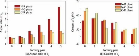
Fig. 8 Microstructure parameters in different planes of spun cylindrical part.
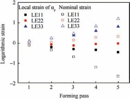
Fig. 9 Nominal strain components and average local strain components of αp at each forming pass.
The corresponding microstructural parameters of αpin the different regions along the ND are shown in Fig.11.As is seen,the aspect ratio values of αpalong the ND are very close in the initial billet.With the forming pass increasing,the aspect ratio of αpin all regions increase (Fig. 11(a)), and the values are slightly high in the outer surface area due to the significant plastic deformation and in the inner surface area due to the formation of new bar-shaped α grains. As for the αpcontent,it increases after the first pass and then gradually decreases.In the central area, the difficulty in the deformation heat releasing enhances the deformation temperature,thus decreasing the microstructural parameter, as shown in Fig. 11(b).Therefore, it can be concluded that the inhomogeneous distribution of αpcontent along the ND is caused by the combined effects of plastic deformation and temperature distribution.Moreover, according to the aspect ratio and content of αpshown in Fig. 11, it is found that the microstructural parameters of αpfluctuate most after the third pass.However,the difference in these parameters reduces after the fourth and fifth passes, which suggests that the homogenous microstructure along the ND of the titanium spun cylindrical part could be achieved after the fourth pass.
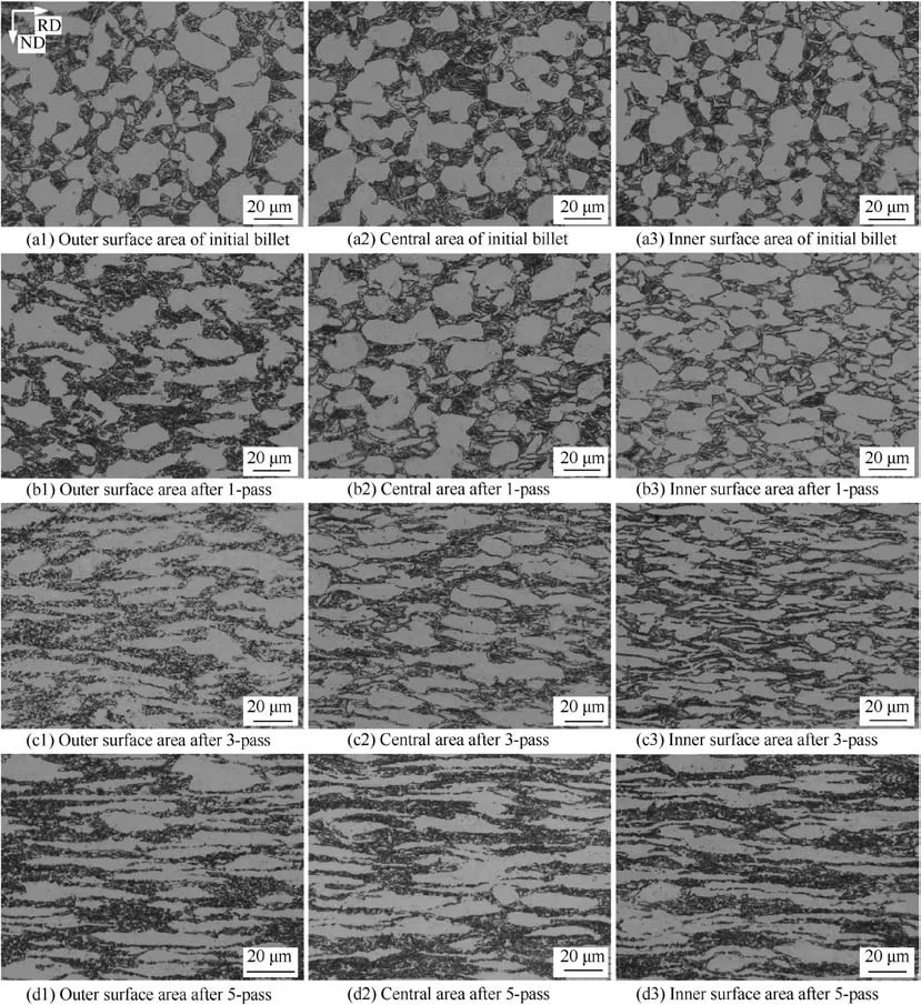
Fig. 10 Microstructure evolution in different areas along ND of spun cylindrical part.
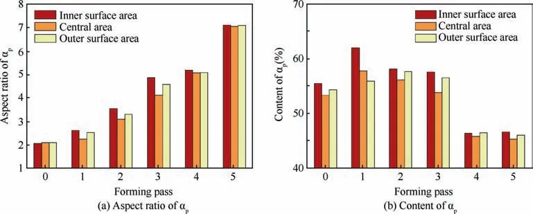
Fig. 11 Microstructural parameters in different areas along ND of spun cylindrical part.
3.4. Hardness inhomogeneity along the thickness direction
The above analyses on microstructural parameters quantitatively reveal the inhomogeneity of αpgrain along the ND of the part, while the comprehensive inhomogeneity of the bimodal microstructure is not characterized. In view of this,the hardness inhomogeneity factor (IF) is used as an index to evaluate the microstructural inhomogeneity development of the spun cylindrical part.6,7The index is defined by the ratio of the standard deviation (Hs) and average value (Have) of hardness, as expressed by the Eq. (5). The lower IF value is,the more homogenous microstructure will be.

To investigate the IF development of the TA15 alloy cylindrical part, the Vickers hardness distribution throughout the thickness of the part is analyzed first. For comparison, the thickness of the cylindrical part after different forming passes is normalized. As seen in Fig. 12, the Vickers hardness increases with the increase of forming pass.After the fifth pass,the average hardness value improves by 10.25% compared with the initial billet due to the grain refinement. It is also observed that the hardness values in the central area of the part are slightly lower than those closing the surface areas.As well known, the strength of the multi-phase alloy largely depends on the strength and content of its constituent phase.28The previous study has indicated that the hardness of αpcontributes most to the integrated hardness of TA15 alloy spun cylindrical part.29Therefore, lower αpcontent in the central area of the cylindrical part (Fig. 11(b)) results in the lower hardness values in this area. Correspondingly, relatively high hardness values in the inner and outer surface areas are attributed to the high content of αpand significant plastic deformation, respectively. Meanwhile, in Fig. 12, the fluctuation of hardness (standard deviation) becomes steady as the flow forming pass increases due to the gradually homogenous phase content and strain variation along the thickness direction.
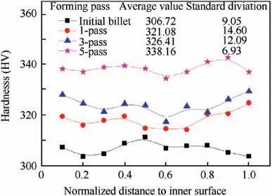
Fig. 12 Distribution of Vickers hardness at different forming passes.
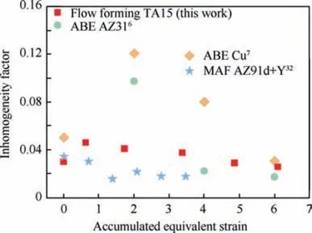
Fig.13 Variation of inhomogeneity factor after flow forming in comparison with previous studies.
The variation of IF shown in Fig. 13 further demonstrates that the microstructural homogeneity is improved with the forming pass increasing. Previous studies explored that the stacking fault energy (SFE) plays an important role in the IF development during forming process.30,31The material with high SFE can achieve a uniform microstructure by high rate of recovery.In the material with low SFE,the recovery occurs slowly due to the difficulty in cross slip, but the CDRX, shear bands, and deformation twins transform the grains into fine structures,thus accelerating the formation of a reasonably uniform microstructure.32These investigations suggest that the IF development is determined by the nature of grain refinement.Therefore, the degree of CDRX and DILS determines the microstructural homogeneity of TA15 alloy spun cylindrical part.2At the same equivalent strain, the microstructural homogeneity of TA15 alloy in flow forming is easier to achieve compared with that of Cu in accumulative back extraction(ABE) process (Fig. 13) because the medium to low SFE of Cu retards the low angle boundaries formed during forming process.7However,the combined effects of dynamic recrystallization and deformation twin of Mg alloys promote the more grain refinement, eventually leading to the more homogenous microstructure in Mg alloys component than in TA15 alloy spun cylindrical part6,32-34Additionally, as seen in Fig. 13,the first pass would disturb the initial microstructural homogeneity, thus a sufficient large number of forming passes are required to achieve a complete homogenous microstructure.After the fourth pass (thickness reduction ratio of 63.16%),the IF value (0.285) is lower than that of the initial billet(0.295), which indicates a TA15 alloy spun cylindrical part with homogeneous microstructure along the ND can be obtained in this case. Undoubtedly, increasing the forming pass further is beneficial to obtaining more homogeneous microstructure of the TA15 alloy spun cylindrical part.
4. Conclusions
In this study, the deformation history and microstructural parameters of TA15 alloy spun cylindrical parts are analyzed to reveal the origin and the development of microstructural inhomogeneity during multi-pass backward flow forming.The main conclusions are drawn as follows:
(1) In the flow forming process, significant compression deformation in the normal direction (ND) leads to primary α(αp)grains compressed in this direction and elongated in the rolling and circumferential directions (RD and CD), while the elongation along the CD is small due to the limited material flow. The difference in nominal strain components finally results in the inhomogeneous morphology of αpin the normal-rolling (N-R),normal-circumferential (N-C) and circumferentialrolling (C-R) planes of the part. With the forming pass increasing, the aspect ratio of αpincreases most in the N-R plane, then in the N-C plane and least in the C-R plane, whereas αpcontent decreases in an opposite trend.
(2) Along the ND of the cylindrical part, the significant plastic deformation near the outer surface area and bar-shaped α grains formed near the inner surface area under the low mandrel temperature increase the aspect ratio and content of αpin these areas.In the central area,the difficulty in the deformation heat releasing enhances the deformation temperature, thus decreasing the microstructural parameters.These inhomogeneous characteristics can be gradually diminished with the forming pass increasing.
(3) Due to the effect of inhomogeneous microstructure, the Vickers hardness values fluctuate along the ND,and the lower values appear in the central area of the cylindrical part.Moreover,the degree of hardness fluctuation gradually decreases with the forming pass increasing. After the fourth pass, the relatively low inhomogeneity factor(0.285) means that a four-pass flow forming with the total reduction ratio of 63%could obtain a homogenous microstructure along the ND of the TA15 alloy spun cylindrical part.
Acknowledgements
The authors acknowledge the financial support from the National Science Fund for Distinguished Young Scholars of China (No. 51625505), the Key Program Project of the Joint Fund of Astronomy and National Natural Science Foundation of China (No. U1537203), National Natural Science Foundation of China (No. 51875467) and the support of Young Elite Scientists Sponsorship Program by CAST of China (No. 2018QNRC001).
Appendix A. Supplementary data
Supplementary data to this article can be found online at https://doi.org/10.1016/j.cja.2019.08.021.
 CHINESE JOURNAL OF AERONAUTICS2020年7期
- CHINESE JOURNAL OF AERONAUTICS的其它文章
- An experimental method for squealer tip flow field considering relative casing motion
- A novel none once per revolution blade tip timing based blade vibration parameters identification method
- Highly efficient computation method for hazard quantification of uncontained rotor failure
- Optimal motion cueing algorithm for accelerating phase of manned spacecraft in human centrifuge
- Effective control allocation using hierarchical multi-objective optimization for multi-phase flight
- Fault-tolerant control and vibration suppression of flexible spacecraft: An interconnected system approach
