Highly efficient computation method for hazard quantification of uncontained rotor failure
Zhenqiang ZHAO, Peng LIU, Yan LIU, Chao ZHANG, Yulong LI,*
a Department of Aeronautical Structure Engineering, Northwestern Polytechnical University, Xi’an 710072, China
b Shaanxi Key Laboratory of Impact Dynamics and its Engineering Applications, Northwestern Polytechnical University,Xi’an 710072, China
KEYWORDS Boundary discretization;Critical point;Hazard probability;Risk angle;Uncontained engine rotor failure
Abstract Uncontained Engine Rotor Failure (UERF) can cause a catastrophic failure of an aircraft, and the quantitative assessment of the hazards related to UERF is a very important part of safety analysis. However, the procedure for hazard quantification of UERF recommended by the Federal Aviation Administration in advisory circular AC20-128A is cumbersome,as it involves building auxiliary lines and curve projections.To improve the efficiency and general applicability of the risk angle calculation,a boundary discretization method is developed that involves discretizing the geometry of the target part/structure into node points and calculating the risk angles numerically by iterating a particular algorithm over each node point.The improved efficiency and excellent accuracy for the developed algorithm was validated through a comparison with manual solutions for the hazard quantification of the engine nacelle structures of a passenger aircraft using the guidance in AC20-128A. To further demonstrate the applicability of the boundary discretization method, the proposed algorithm was used to examine the influence of the target size and the distance between the target and rotor on the hazard probability.
1. Introduction
The safety and reliability of airplanes have been improved in recent decades with advances in aircraft design.A key concept for ensuring airplane safety is to understand and predict the uncertainty of the system.1The goals of the United States Federal Aviation Administration (FAA) for aeronautical safety research and development may be simply stated as providing improvements that will prevent or avoid an accident and, in the event that an accident does occur,to improve survivability for the passengers and crew.2As the aero-engines provide propulsion for the aircraft, their safety and reliability is directly connected with the safety of the plane and its passengers. An Uncontained Engine Rotor Failure(UERF) is one of the most critical hazards for an aircraft, as it could cause a catastrophic failure.
Because the operating conditions for an aircraft engine involve high temperatures, high speeds, and high stress, it is possible for the components of the turbine engine rotor (such as disks and blades) to fail due to fatigue-induced fracture.When a component is released while the engine is operating at full thrust,broken parts are thrown through the engine casing under an extremely high centrifugal force. Although manufacturers of turbine engines and Auxiliary Power Units(APUs)are making efforts to reduce the probability of uncontained rotor failures through the introduction of new material systems and new structure designs, uncontained compressor and turbine rotor failures still occur.3Numerous research and development efforts have been made to enhance the containment capability or the impact tolerance of turbine engine containment structures against an engine blade-out event,4-9and these efforts have greatly enhanced the safety and efficiency of engine containment structures. However, it is still necessary to consider conditions where the engine casing is unable to contain the high-energy fragments of the rotor disks or blades.Once fragments penetrate the engine casing,they are able to cause damage to other critical structures or system components on the aircraft, causing a catastrophic accident.10Fig. 1 presents photographs of aircraft that have experienced uncontained engine rotor failure.
It is necessary to conduct safety assessment for the risk of the critical systems or structural components attacked by the uncontained rotor debris, considering the uncertainty of UERF accident.11,12The FAA’s Aircraft Catastrophic Failure Prevention Program (ACFPP) was created in 1989 with the mission of conducting research to reduce the risk of catastrophic aircraft accidents and fatalities. One primary focus of the ACFPP is on uncontained engine failure.13In 1997, the FAA published advisory circular AC20-128A,14which proposed a verification method to determine if an aircraft meets the airworthiness standards and requirements for preventing UERF. This advisory circular illustrates the basic concepts about UERF including definitions, assumptions and probable failure modes, along with detailed instructions on how to minimize the hazards to an airplane in the event of uncontained engine or APU rotor failures. This advisory circular also provides some precautions to take during the design process, and the appendix of the circular presents the methodology to be used in the safety analysis.14The guidance in this circular has been adopted by the aviation industry in the USA.
Since then, the analysis methodology in AC20-128A has become the basis for design and verification of uncontained rotor failure. For example, the United States Department of Defense,in its airworthiness approval guidelines MIL-HDBK-516B published in 2005,15suggests using AC20-128A as a reference in the technical documents for military aircraft airworthiness approval. The FAA has also sponsored the development of an analytical tool used for conducting rotor burst assessment,known as the Uncontained Engine Debris-Damage Assessment Model(UEDDAM),which incorporates fragment penetration,enables system-level hazard assessment,and considers impacts by multiple debris fragments. Seng et al.16utilized UEDDAM to assess the risk of uncontained engine failures for a small business jet and a twin-engine aircraft.
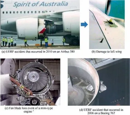
Fig. 1 Views of UERF accident.
UERF has been studied by many researchers for the purpose of developing more efficient and convenient methods for hazard quantification while meeting the design requirements for uncontained safety analysis. Li et al.17and Wang et al.18applied the risk analysis process for uncontained aero-engine rotor failure that was proposed in AC20-128A to the risk analysis of a small business jet. Jia and Song19developed a new method to determine the translational risk angle for uncontained rotor fragments based on the methodology in AC20-128A using a simplified procedure that still ensured accuracy. Zeng et al.20presented a method to identify the hazards caused by uncontained rotor failure, based on the results from a functional hazard analysis and a fault tree analysis of the entire plane. The method proposed by Zeng could be used to examine the combined effects of simultaneous impacts by multiple disk fragments, and it provides more detailed and reliable suggestions for improving safety in the design of aircraft.
Following the procedure of AC20-128A,14the quantification of hazard events and determination of risk angles of the system or structural components must be determined manually based on the geometric models of the aircraft.This is a tedious work since it involves a large number of drawing of auxiliary lines and curve projections for regular and irregular geometries. In order to improve the design efficiency and accuracy,the development of automatic analytical or numerical tools are necessary. For this purpose, Wang21utilized the Monte Carlo method in the analysis of UERF to determine the failure probability for all components due to damage from flying fragments, which required a large number of repeated numerical trials. The verification method developed by Wang provides an alternative way to quantify hazards in the UERF procedure, but it is only applicable for disc fragments that are presumed to fly out with infinite kinetic energy. In addition, this method requires a large number of trials to achieve sufficient accuracy due to its incapability in recognizing directly the geometric profile and locating accurately the relative location of the target.
Inspired by the broad applications of discretization methods in engineering, such as the Finite Element Method(FEM)22and the Smoothed Particle Hydrodynamics (SPH)method23, as well as a boundary particle resampling method presented by Sandim et al.24for surface reconstruction, this work proposes a boundary discretization method to determine the risk angle for hazard identification and quantification in the analysis of UERF.The proposed new method can improve the efficiency of the risk analysis for uncontained engine rotor failure without the need for manually building auxiliary lines and curve projections as required in the AC20-128A method.In the new method,a boundary discretization method is established for calculating the risk angles by discretizing the geometry of the target into node points in order to produce results that are easy to interpret and feasible for program realization.Following an introduction to this new method, an example is presented to demonstrate the convergence of the presented approach,and the accuracy is validated through a comparison of the calculated results with manual solutions for hazard quantification of the nacelle structures of a small transport aircraft.In addition,a parametric study was conducted to examine how the size of the target and its distance from the engine rotors will affect the hazard probability.
2. Theory and methods
2.1. Hazard identification and hazard quantification
As shown in Fig. 2, the hazard assessment process for UERF as proposed in AC20-128A can be divided into two parts:hazard identification and hazard quantification. In hazard identification, where the fragment trajectories are established and triggering analysis is conducted, the aim is to determine the basic hazard events that would lead to a catastrophic accident in the event that a UERF occurs. Once the hazard events are identified, some events with high risk can be eliminated by optimizing the layout or by establishing reasonable precautions to prevent debris from damaging critical parts and structures. However, the remaining hazard events cannot be completely eliminated,and these are referred to as residual hazard events. The residual hazard events are then assessed quantitatively against the catastrophic failure conditions of an uncontained engine failure in a process known as risk analysis or hazard quantification.25In the process of hazard quantification, the probability of each hazard event is first calculated based on certain simplification assumptions, and a further evaluation is conducted to check whether sum of the risk probabilities of all hazard events for the entire plane meet the airworthiness requirements.
One key factor in hazard quantification is the determination of the risk angle—the critical angle within which the target part or structure will be hit by rotor fragment debris—which depends on the position of the target part/structure in relation to the engine rotors of the engine experiencing UERF.In other words, a debris fragment will be in contact with the target when its path of motion falls within the range of the risk angle,and there will be no contact if the path of the flying debris is outside the area of the risk angle. The critical range of path trajectories for rotor fragments that will result in impacts with a part/structure are generally identified by two angles: the spread risk angle and the translational risk angle.The methods for determining the spread risk angle and the translational risk angle can be found in Appendix I of AC20-128A.14
Fig. 3 presents the threat window as illustrated in AC20-128A.In the diagram in Fig.3(a),T1indicates the tangent lines between the locus of the fragment centroid and the target envelope, and the radius of the fragment sweep path R is defined as half of the maximum dimension for the debris.The radius of the fragment sweep path R is considered in the determination of the translational risk angle. T2indicates the critical sweep lines of the target corresponding to the two tangent lines of the locus of fragment centroid,which cross points N1and N2. The locations of N1and N2are determined based on the radius of the fragment, and the angle between the two T2lines is defined as the translational risk angle. For a case where the target is outside the rotation plane of the rotor(Fig. 3(b)), it is necessary to first project the envelope of the target onto the rotation plane and then determine the translational risk angle according to the procedure introduced above.In the determination of the spread risk angle (Fig. 3(c)), the dimensions of the debris are ignored due to the assumption in AC20-128A that the released fragment rotates about its centroid without tumbling.14It is important to note that the types of debris and the corresponding maximum spread ranges were stipulated in AC20-128A. For example, the ejection trajectory of a single fragment comprising one third (⅓) of the turbine disc should not deviate from the plane of rotation more than±3°; thus, the maximum spread ranges for an intermediate fragment and a small fragment are ±5° and ±15°,respectively.14,26
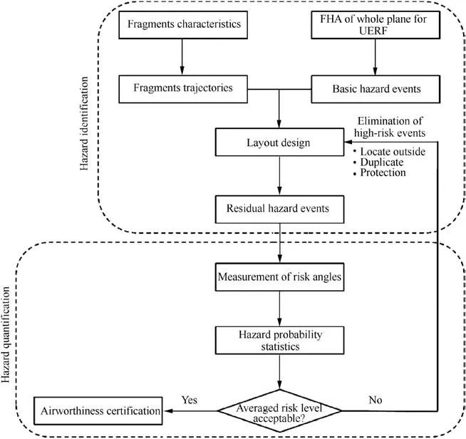
Fig. 2 General flow diagram for risk analysis in a UERF event.
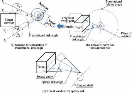
Fig. 3 Risk analysis using AC20-128A method.
The methodology outlined in AC20-128A uses a rectangular target as an example,and the method itself is only straightforward for parts having a regular shape. However, if the geometric profile of the target part has an irregular surface,then the determination of critical locations of the sweep lines for the debris will become difficult and complicated and,hence, may lead to inconsistent or inaccurate results. Thus, it is necessary to develop a new method that can accurately and efficiently predict the impact of debris with target parts/structures having complex shapes.
2.2. Boundary discretization method
Assessing the hazards for an entire plane following the methodology in AC20-128A involves determining the risk angle measurements for a large number of lines, cables, and components as well as for some primary structures.This necessitates producing a large number of drawings of auxiliary lines and curve projections, which are burdensome and tedious to create. Thus, it is necessary to develop computational tools for the measurement of the risk angles,as this can enhance significantly the efficiency of the risk analysis and safety design.
One key step to determine the risk angle is identifying the critical points on the target part/structure,which are the points of tangency between the fragment sweep path and the target envelope, as shown in Fig. 3(a). The critical points on the target envelope change with the variation in the relative locations of the rotor and target as well as with the different dimensions for the debris in each rotor stage. For the example shown in Fig. 3, the critical point is easy find for a target envelope having a regular shape.Generally,for a polyhedral target,the critical points must be located at the vertexes of the target.In this case, we do not have to determine exactly which vertex is the critical one; we only need to draw a separate sweep path for each vertex of the target envelope.The maximum of the angles between any two paths is then determined as the spread risk angle or the translational risk angle.
However, if the target contains a curved surface such as a cylinder or sphere, the above method is not applicable, as the target may have no vertex and the critical point may not be located at the vertices. In either case, the critical point should be located inside the envelope of the target so that the boundary curves or the surface can be discretized into points according to a certain predefined density. After that,the same steps can be taken for each discrete point as were used to deal with the vertex of a polyhedron. Obviously, the density of the points along the curvature will affect the accuracy of the results. More details regarding the convergence study will be presented in Section 3.1.
2.2.1. Calculation of the spread risk angle
When determining the risk angle of a target using discretized points on the boundary,a reference vector is predefined to simplify the calculation,in which the spread or translational angle is considered as the angle between the sweep path of each discrete point and the reference direction. Fig. 4(a) shows a diagram showing how the spread risk angle calculated using a case for a simplified cuboid, where the sweep paths corresponding to each vertex of the envelope are plotted. Here,the normal vector of the rotation plane (which can be calculated by using the center coordinates of any two rotors on the engine shaft) is considered as a reference direction, and the vector of each sweep path can be easily calculated based on the coordinates of each vertex and the center point of the rotor. Next, we can calculate the spread risk angle for a large fragment (⅓of the disc) using
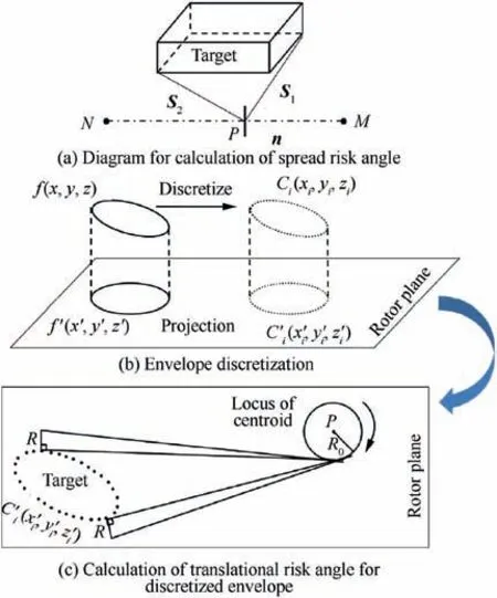
Fig. 4 Risk analysis for boundary discretization method.

where αiis the angle between Siand n,and ψ is the spread risk angle.It should be noted that the maximum spread range of a large fragment (⅓disc) is required to be within±3° (according to AC20-128A); thus, the spread risk angle can be expressed as Eq. (2).
2.2.2. Calculation of the translational risk angle
To measure the translational risk angle, it is necessary to project the target envelope onto the rotation plane of the rotor.Boundary discretization can simplify the projection process,as the projection of points is theoretically easier than the projection of irregular curves.Fig.4(b)shows the process for producing a sketch of the projected curves and points. For the boundary discretization method, each point Ci(xi, yi, zi) can be projected onto the rotor plane, as shown in Fig. 4(b). Here N (xN, yN, zN) and M (xM, yM, zM) are any two points on the engine shaft, P (xP,yP,zP) is central point of the rotor, and Ci′(xi′, yi′, zi′) are projected points on the rotor plane. The coordinate value of the projected points Ci′can be calculated by substituting the coordinate value of each point into Eq.(3).


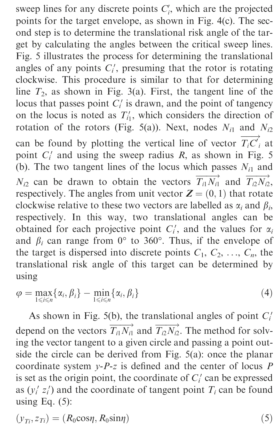
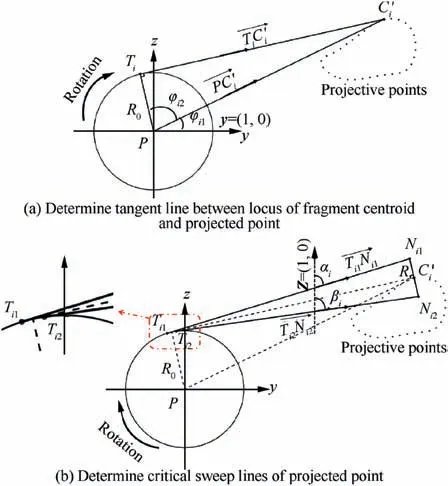
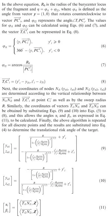
Fig. 5 Determination of translational angles for any projected point.
3. Results and discussion
In the previous section, the background and the numerical methods used in the proposed boundary discretization approach for risk analysis of UERF were introduced. To demonstrate the capability of the proposed method, engine mounts containing 28 tie-rods were analyzed using two approaches: a manual approach introduced in AC20-128A and an automated approach using the proposed boundary discretization method. The accuracy and efficiency of the automated approach were determined by performing a convergence analysis through comparing the results for the automated approach to those obtained using manual measurements according to AS20-128A, and validation of the proposed approach was conducted by considering a UERF scenario involving two engine nacelles on a small aircraft. In addition, a parametric analysis was conducted to investigate the relationship between the resulting hazard probability and the target part size as well as the distance between the rotor and the target part. The following subsections present the results for each analysis.
3.1. Convergence analysis
From the description of the boundary discretization method presented in the previous section, it can be inferred that the calculation results are highly dependent on the density of discretization of the target boundary. The convergence of this algorithm can be demonstrated by comparing the calculation results with the manual measurements for a specific component.As shown in Fig.6,a tube target similar to a fuselage section with a diameter of 4 m is analyzed using the algorithm presented in this paper and compared with measurements obtained with the aid of a computer-aided three-dimensional interactive application (CATIA) model using the official method proposed in AC20-128A. The radius of mass centroid locus R0for a large fragment that represents one third of the rotor disc is 87.7 mm and the radius of the fragment sweep path R is 151.9 mm, which are determined for the power turbine rotor of a turboprop engine.In addition,the target envelope is also discretized into points with different densities in CATIA. The coordinates of the discretized points are then used as inputs in the boundary discretion method.
The intervals of the discretization points for the tube target shown in Fig. 6 are set at 4000 mm, 1000 mm, 500 mm,300 mm, 200 mm, 100 mm, 50 mm and 10 mm; the total number of discretization points for these intervals are 16,24,50,84,126, 378, 1225 and 26397, respectively. Hence, the translational risk angle and the spread risk angle of the tube target can both be calculated by importing the discretization points into the boundary discretization method proposed in Section 2.2. The numerical calculated results of the tube target with different densities of discretization points are summarized in Fig. 7. From Fig. 7, it can be noticed that both the calculated translational and spread risk angles increase as the number of discretization points increase,and the calculated results converge near the results for the manual measurements with a negligible error (<1‰).
3.2. Validation of the boundary discretization method
In order to verify the accuracy of the boundary discretization method, quantitative risk analysis for two engine nacelle frames of a small aircraft are used as a demonstration. In this example, each nacelle frame contains a total of 14 tie rods which surround the engine in all directions. The diameter of each tie rod is 60 mm, while the lengths of the tie rods vary from 960 mm to 1372 mm. For this rotor stage, the coordinates for the center of the engine shaft are (13770, -4380,928.712),the radius of the mass centroid locus of the large disc fragment R0Lis 87.7 mm,and the radius of the fragment sweep path RLis 151.9 mm. For the intermediate fragment, the radius of the mass centroid locus R0Mis 139.2 mm, and the radius of the fragment sweep path RMis 41.5 mm.
The spread and translational risk angles of each rod corresponding to one of the power turbine rotors in the left engine were plotted (as shown in Fig. 8), and partial results of the manually measured and calculated risk angles(both the initial and final angles of intersection are recorded) for selected tie rods are listed in Tables 1 and 2, along with the hazard probability for each rod calculated using Eq. (12). In Eq. (12), the maximum spread angle is 6° for the large fragment (⅓disc)and 10° for the intermediate fragment, since the prescribed maximum spread ranges for the large fragment and intermediate fragment are±3° and±5°, respectively.
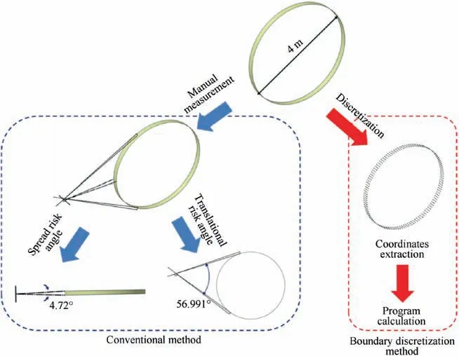
Fig. 6 Scheme for determination of risk angles using conventional method and boundary discretization method.
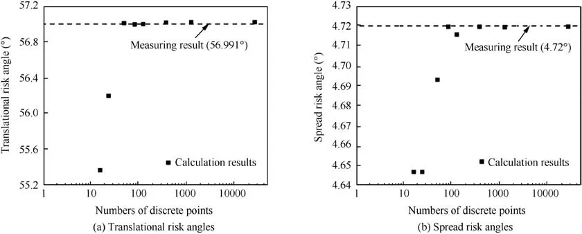
Fig. 7 Calculated risk angles with variation of discretization density.
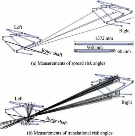
Fig.8 Measurements of spread and translational risk angles for tie rods in two nacelles for a UERF event.

Tables 1 and 2 present partial results of the hazard quantification for the tie rods in the nacelle of the right engine that may be damaged by fragments thrown from one of the power turbine rotors in the left engine. From the results listed in Tables 1 and 2,it can be noticed that the boundary discretization method proposed in this study shows excellent accuracy.It can also be noticed that the hazard probability for the large fragment is much higher than that for the intermediate fragment due to the fact that the sweep path of the large fragment is nearly four times wider than the path for the intermediate fragment. A comparison of the different hazard probabilities for the rods in the left and right nacelles demonstrates that the components closer to the left engine have a higher risk of being struck by debris.
4. Parametric analysis
The validated boundary discretization method can be further used to investigate the relationship of hazard probability and the distance between rotor and the target as well as the target size. In this section, a hypothetical target having a spherical shape is positioned within the area of large debris dispersal,with the assumption that the center of the sphere is on the rotation plane of the specific rotor. Fig. 9 shows the distance d between the target and specific rotor as well as the radius of sweep path R; these parameters can be determined according to the dimensions of the disc and blades,14where r indicates the radius of a spherical target and Rdiscindicates the radius of the disc.
The hazard probabilities for a spherical target being impacted by the disc debris were calculated, and the results are shown in Fig. 10, where the target radius r and distance from the rotor d are normalized by the radius of the rotor disc. As can be noticed from this figure, the hazard probability increases with the increase in target size and the decrease in the distance of the rotor from the target. Both the results for the large fragment (representing one third of the rotor disc) and those for the intermediate fragment indicate that the hazard probability increases by several times when the distance between the target and the engine is less than ten times the radius of the rotor, even though the target is small. This result indicates that the distance between the target and the rotor is more critical than target size for hazard control.
With the increase in target size, the hazard first increases rapidly but increases more slowly after the normalized r/Rdiscgoes beyond a certain point(represented by the red solid line),as shown in Fig. 10. This is because the spread risk angle becomes constant, with a maximum spread angle of 6° for a large fragment(representing ⅓disc)and 10°for an intermediate fragment when the target size is outside the maximum spread range,according to the debris ejection model proposed in AC20-128A.14As a result, the hazard probability will be mainly driven by the increase in the translational risk angle once the spread angle exceeds a certain threshold.
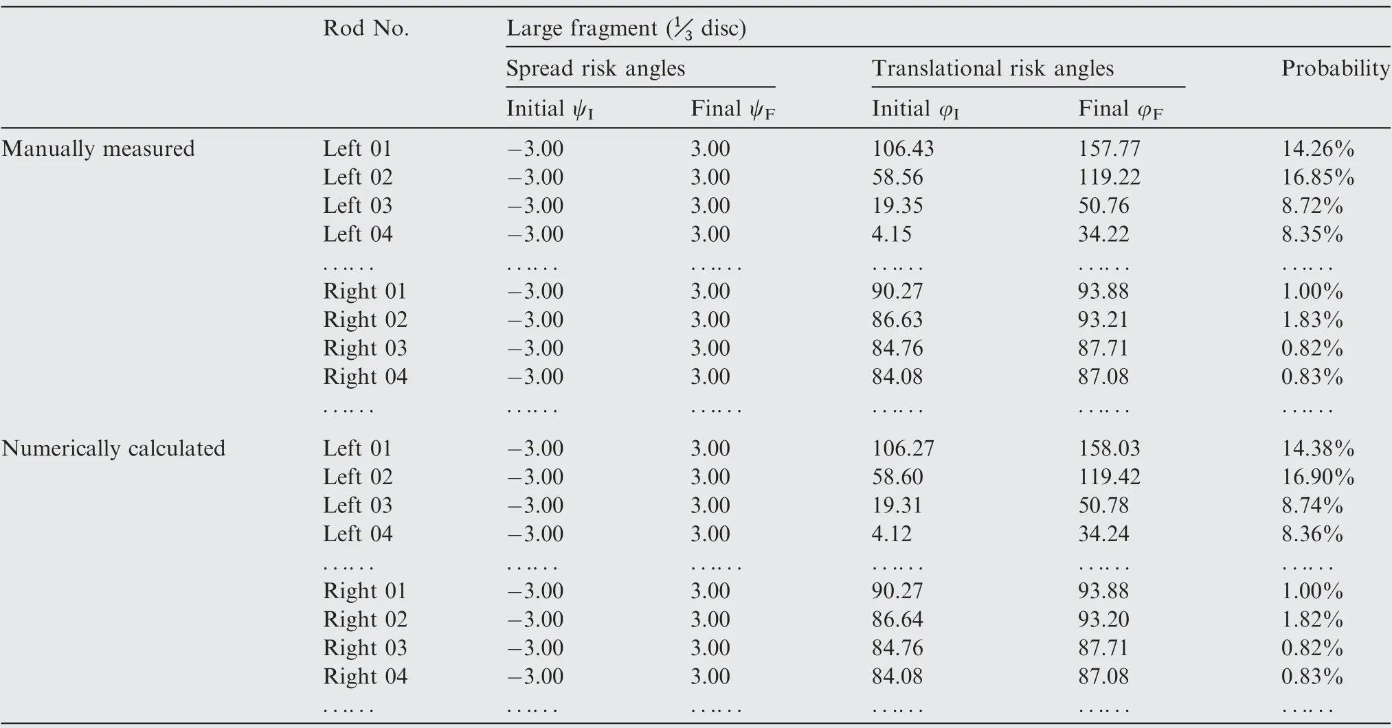
Table 1 Comparison of manually measured and numerically calculated results for a large-sized fragment (⅓disc).
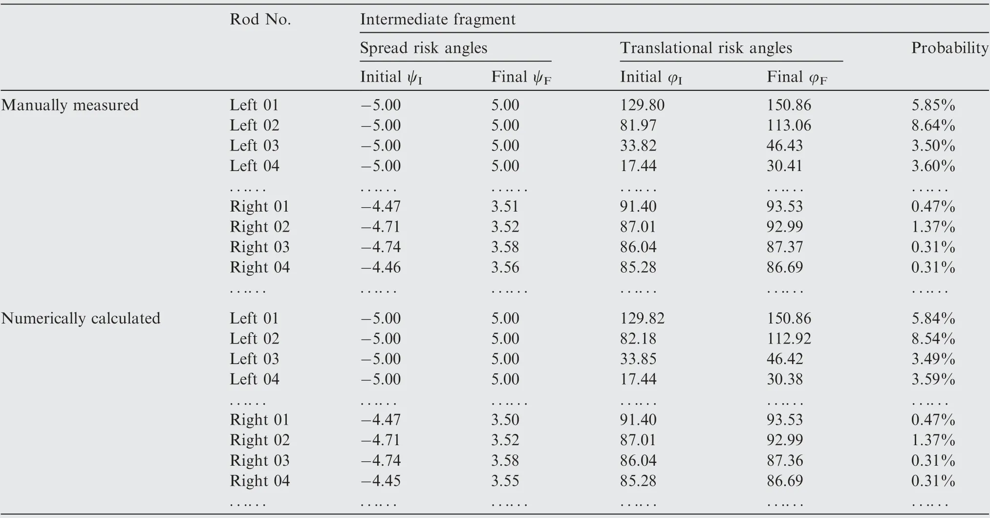
Table 2 Comparison of manually measured and numerically calculated results for an intermediate-sized fragment.
5. Conclusions
Quantitative assessment of the hazard for an uncontained rotor failure is a very important part of safety analysis.In this study,a boundary discretization method was developed to calculate risk angles for a UERF event,and the results were compared to risk angles determined by using the methodology in FAA advisory circular AC20-128A. Based on the findings of this study, the following conclusions can be made:
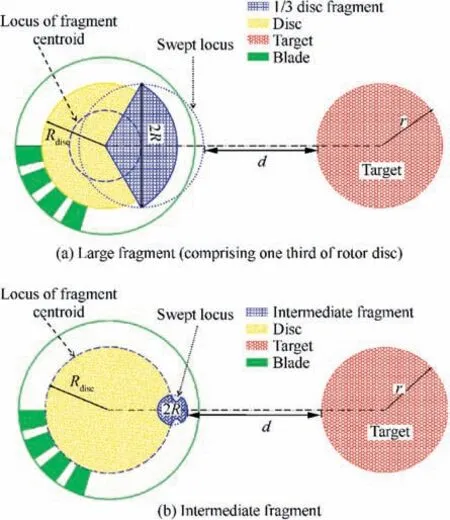
Fig. 9 Numerical models of hazard quantification for large and intermediate fragments.
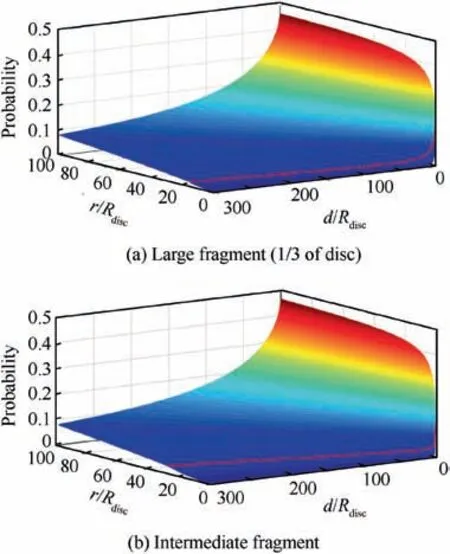
Fig. 10 Numerically predicted probability distributions with target size and its distance from rotor. (Note: In this figure, the solid red line represents the boundary of spread range of the fragment).
(1) The convergence analysis using a tubular model to represent a fuselage segment indicated that translational and spread risk angles calculated using the boundary discretization method increase with the number of discrete points, and the calculation results converge near the results of the manual measurements (made using the methodology in AC20-128A)with a negligible error.Thus, it can be concluded that the proposed algorithm can effectively calculate the risk angles for a target in a UERF scenario.
(2) The method suggested in AC20-128A for determining the translational and spread risk angles in a UERF scenario can lead to inconsistent or inaccurate results when the geometric profile of the target has an irregular surface. However, the boundary discretization method developed for risk angle calculation of uncontained rotor failure is not restricted by the target shape due to its discrete characteristics. Thus, the proposed method is expected to be applicable for targets with various geometries.
(3) In the validation of the proposed boundary discretization method, two engine nacelle frames on a small aircraft were considered. The time required to perform manual measurement of the translational and spread risk angles for the 14 tie rods of the nine rotors in the left engine using the manual methodology in AC20-128A(which involves sketching the auxiliary lines and curve projections) was approximately 40 h. In contrast, the calculations of the risk angles using the proposed boundary discretization method required only about two hours when using a quad-core computer that has an Intel I7-6700 processor with a clock speed of 3.4 GHz and that has 8 GB of RAM. Thus, the proposed method is feasible for program realization, as it greatly improves the efficiency of conducting risk analysis for UERF.
(4) A parametric study that was conducted using the proposed boundary discretization method to determine the influence of target size and the distance between the target and the engine rotors on the hazard probability indicated that the proposed method is able to explicitly show the distribution pattern of hazard probability,and it revealed that the distance between the target and the rotor is more critical for hazard control than the target size.From the results of the parametric study,it can be inferred that the important system components and pipes located in the nacelle or behind the leading edge of the wing near the nacelle would face tremendous risks.Thus,enhancing the impact resistance of an engine fan casing or a nacelle structure to prevent the penetration of rotor fragments is the most effective way to reduce the flight risk due to UERF.
The method proposed in this study can be easily adopted to assess the UERF safety of a full-scale plane and to assist in the layout optimization of aircraft systems. The numerical results can be used to directly identify the hazard of each target at the stage of elementary layout design for an aircraft,using information on the size of the target part and its distance from the engines. Moreover, the high-risk region for impacts from rotor fragments can be predetermined according to the engine mounting position and the rotor dimensions provided by the manufacturer, and this information will be useful for improving the efficiency of the design layout for the aircraft.
Acknowledgement
This work was supported by the National Natural Science Foundation of China (No. 51706187).
 CHINESE JOURNAL OF AERONAUTICS2020年7期
- CHINESE JOURNAL OF AERONAUTICS的其它文章
- An experimental method for squealer tip flow field considering relative casing motion
- A novel none once per revolution blade tip timing based blade vibration parameters identification method
- Optimal motion cueing algorithm for accelerating phase of manned spacecraft in human centrifuge
- Effective control allocation using hierarchical multi-objective optimization for multi-phase flight
- Fault-tolerant control and vibration suppression of flexible spacecraft: An interconnected system approach
- Trajectory tracking control of a VTOL unmanned aerial vehicle using offset-free tracking MPC
