A novel none once per revolution blade tip timing based blade vibration parameters identification method
Weimin WANG, Xulong ZHANG, Dongfng HU, Dengpeng ZHANG,Pul ALLAIRE
KEYWORDS Blade tip timing;Blade vibration;Parameter identification;Turbomachinery blades;Vibration analysis
Abstract The vibration caused blade High Cycle Fatigue(HCF)is seriously affects the safety operation of turbomachinery especially for aero-engine. Thus, it is crucial important to identify the blade vibration parameters and then evaluate the dynamic stress amplitude. Blade Tip Timing(BTT) method is one of the promising method to solve these problems. While, it need a high resolution Once Per Revolution(OPR)signal which is difficult to get for the aero-engine.Here,a Coupled Vibration Analysis (CVA) method for identifying blade vibration parameters by a none OPR BTT is proposed.The method assumes that every real blade has its own vibration performance at a given speed. Whereby, it can take any blade as the reference blade, and the other blades using the reference blade as the OPR for vibration displacement calculating and further parameter identifying. The proposed method is validated by numerical model. Also, experimental studies are carried out on a straight blade and a twisted three dimensional blade test rig as well as a large industrial axial compressor respectively. The results show that the proposed method can accurately identify the blade synchronous vibration parameters and quantitatively evaluate the mistuning in bladed disks, which lays a foundation for the reliability improvement of aero-engine.
1. Introduction
Blades are core component of turbomachines, and the vibration is the crucial important factor affecting their safe and reliable operation.1-3In recent years,fatigue failure and accidents caused by blade vibration are still particularly prominent.4-7In all of these case,the blade mistuning caused by manufacturing tolerances,material defects,and operational wear and damage will lead to vibration localization which will lead to high stress even to High Cycle Fatigue(HCF) failure.8,9Therefore, the evaluation of blade mistuning degree and identification vibration parameters of the blade is of great significance to the blade safety evaluation, fault early warning and blade damage diagnosis.10
Blade vibration measurement methods are mainly divided into contact and non-contact methods. Contact measurement method is strain gauge based method. It can accurately measure the dynamic strain of blade, but it is generally impossible to measure all blades at the same time and it is usually used as a verification method.11,12Blade Tip Timing(BTT)is the main non-contact method to measure blade vibration at present,this method measures the arrival time of each rotating blade by a number of sensors mounted on the casing, and compares it with the arrival time when the blade is not vibration, then the vibration displacement of the blade is calculated by the difference between these two times. The displacement data can then be analyzed to obtain the vibration parameters like vibration amplitude, resonance center frequency, quality factor,damping ratio and the Engine Order(EO)in resonance condition, especially the amplitude and frequency, for these parameters are closely related to the failure and damage of the blade.13There are various methods for BTT based blade vibration parameter identification.Most of them require a Once Per Revolution(OPR)sensor.14-16While,it is difficult to get a high resolution OPR signal for aero-engine.So a none OPR method is urgently need. A novel none OPR Straight Line Fitting(SLF)-BTT algorithm is reported by Russhard.17It shows a significant effective in reducing measurement uncertainty.Later, Duan et al.18proposed a blade resonance parameter identification method based on Reference To one Sensor(RTS)-BTT method without OPR sensor. The principle of the none OPR BTT is to find other objects that can be used as stationary references to replace the OPR sensor, no matter the references is assuming static or actual static. Through the theoretical analysis of the above two kinds of methods, we can find: The SLF-BTT17method can directly obtain the vibration displacement of the blade,and have chance to realize online real-time monitoring.However,due to the disadvantage of the least squares linear fitting method itself, that is, the fitting reliability is different at each fitting point. For blades far from the midpoint of the blade number, the reliability of the result is not as high as the midpoint. It is easy to imagine that a slight error in slope will have a significantly greater effect on the points at both ends than on the midpoint of the line segment. Therefore, in the low operation speed or synchronous vibration occurs, the difference in the Time Of Arrival(TOA) of the blades within one rev is large, which will result in a large slope error of the fitted straight line, and the error of the fitting result increases. The RTS-BTT18method cannot obtain the blade vibration reference to static state directly, it can only be used as a means of identifying synchronous vibration parameters of blades, and difficult to realize online realtime monitoring.
Generally, the bladed disks used in turbomachinery are designed to be cyclically symmetric, so that every blade on the disk will be identical, but manufacturing tolerances,material defects,and operational wear and damage make each blade slightly different from other blades, these variations(referred to as mistuning) alter the frequency of the blades.In this paper, a new blade vibration parameters identification method without the OPR is developed. One of the blades is used as the reference blade,and the remaining blades are taken as relative to the reference blade. The none OPR blade vibration calculation method is deduced and the blade vibration analysis method is put forward based on Coupled Vibration Analysis (CVA) of mistuned blades. Here we call this as Reference To one Blade (RTB)-BTT method. The accuracy of the method is verified by simulation, and then experimental studies are carried out on a straight blade test rig, a twisted three dimensional blade test rig and a large industrial axial compressor. The experimental results show that the proposed method can accurately measure the blade vibration and identify the blade mistuning, and it is effective and feasible in vibration monitoring and safety evaluation of turbomachines blades.
2. BTT data analysis method
2.1. Calculating the vibration displacement of blades
The BTT method is shown in Fig.1.Here,Bb(b=1,2,...,nb,nbis the number of blades)indicates the blade numbered b,tKnand tKn+1are the timestamp from OPR sensor,K indicates the OPR.Δt1n,Δt2nand so on represent the difference between the time of B1and B2reaching the blade tip sensor and tKn. For one non-vibrating blade, the blade arrival time is the theoretical arrival time, the actual arrival time is measured by the blade tip sensor.
As shown in Fig. 2, the circumferential vibration displacement of blade tip in the nth rotation can be expressed as19:

where, xbnis the circumferential vibration displacement of blade tip in the nth rotation,TKnis the time of one revolution,tbnis the timestamps of Bb, tKnis the OPR timestamps, vKnis the linear velocity at blade tip, R is the radius of the blade tip, DCb,Kis the arc length in the physical sense between the blade Bband the OPR, which is a constant.
When the OPR signal is unavailable, the tKnand vKnis difficult to get. Taking the blade B1as the reference blade, the remaining blade vibration at the nth rotation can be expressed as:

Compared with the blade tip circumference, the blade vibration displacement is very small. Therefore, the blade tip velocity is approximately equal to that calculated with the OPR signal and a certain blade tip signal, so there is v1n≈vKn, and then Eq. (3) will be:

Eq. (5) can be rewritten as:


Fig. 1 Theoretical foundation of BTT.
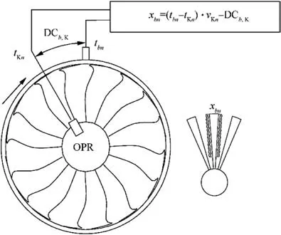
Fig. 2 Schematic diagram of BTT measuring blade vibration.
Substitute Eq. (1) to Eq. (6), it can be simplified as:

From the Eq.(7),it can be seen that the blade vibration calculated by the none OPR method is actually the difference between the actual vibration displacement of the calculated blades and the reference blade. In other words, it is the vibration of the calculated blade relative to the reference blade.
2.2. Parameter identification of blade synchronous vibration
Except the reference blade,all blade vibration can be obtained by Eq.(3).The DCb,1can be obtained by calibration.When the blade does not vibrate ^xbn=0,and the arc length DCb,1corresponding to the vibration in whole rotational speed ranges can be expressed as Eq. (8). Here, the influence of rotation speed on the blade timestamp is indicates as:

Then, the synchronous vibration parameters of blades are analyzed by using the vibration displacement without the arc length. In the case of synchronous (the blade vibration frequency is an integer multiple of the rotational frequency)vibrations,20the blade tips have nominally the same displacement at each revolution if the rotor runs at a constant speed,which makes data analysis more difficult. Hence, the blade accelerates in the range of working speed (a so-called ‘sweep’or ‘run up’) during measurement and the vibration data obtained by blade tip sensor are (^xb, n) and (Ω, n). They can be combined to obtain data (^xb, Ω), where n represents the number of revolution,Ω is the rotation frequency.In this case,the displacement data will vary for each revolution and the synchronous vibration parameters of the blade will be identified.
There are mainly single parameter method, double parameter method,21sinusoidal fitting method22and autoregressive method for blade vibration parameter identification based on BTT.23In this section, a parameter identification method of blade synchronous vibration based on CVA is proposed. This method identifies the synchronous resonance parameters like vibration amplitude, resonance center frequency and quality factor as the rotor rotating speed of sweeps from low to high.The single frequency vibration response of blades can be written as:
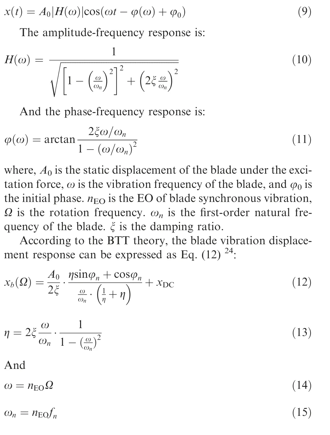
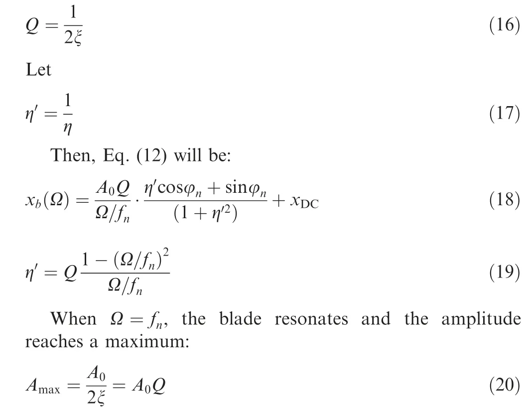
When none OPR signal is available, the vibration displacement calculated by the proposed method is the difference between the actual vibration displacement of the calculated blades and the reference blade.Eq.(18)is not feasible to identify vibration parameter, the new method is presented.
By substituting Eq.(18)into Eq.(7),the vibration displacement response under the none OPR method can be expressed as:
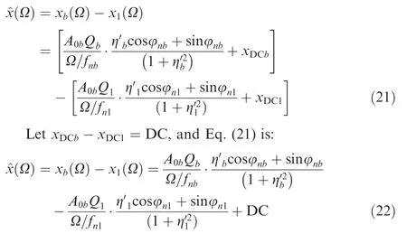
Where, x(Ω )is the actual synchronous vibration displacement of blade,Q is the quality factor,φnis the phase of blade vibration,xDCis the DC offset of vibration,fnis the resonance center frequency of blade synchronous vibration. The subscript b and 1 represent the calculated blades and the reference blade respectively.
It can be seen from Eq.(22)that the vibration displacement response obtained by the none OPR method is similar to the superposition of two single-frequency vibration displacement responses, which is similar to coupled vibration. The closer the resonance center frequency between the reference blade and the calculated blade is,the stronger the coupling of vibration displacement is. That is the characteristics of the mistuning blades. Assuming that the reference blade is tuned, the following are discussed in two cases according to the mistuning characteristics of the calculated blades.
When the calculated blade is mistuned, the coupling of the vibration displacement between the calculated blade and the reference blade is weak,and there will be two resonance peaks in the vibration displacement within the harmonic resonance speed range, one belongs to the reference blade and the other belongs to the calculated blade. Using the Levenberg-Marquardt (LM) method to fit the two resonance peaks, and the resonance parameters corresponding to the two resonance peaks can be obtained respectively. Because all calculated blades are referenced by the same reference blade, by fitting the coupled vibration displacements of several calculated blades, the same part of the fitting results is the vibration parameters of the reference blade,then the resonance parameters of the reference blade and the mistuned calculated blades are obtained.
When the calculated blade is tuned, the coupling of the vibration displacement between the calculated blade and the reference blade is strong, the resonance peaks of reference blade and calculated blade will counteract or superimpose,and there will not be two completely independent resonance peaks. At this time, the vibration parameters of the reference blade separated from the coupled vibration displacement of the mistuned blade can be brought back to the coupled vibration displacement of the tuned blade, and then the actual vibration parameters of the tuned blade can be obtained by the LM method.
This method requires the existence of mistuned blades in the bladed disks, if all blades are tuned, the results obtained by this method will be unreliable. However, the actual bladed disks or the excitation force on blade are often mistuned, so this method is applicable. This will be verified by experiments later. Of course, this method can also be used as a means to detect the mistuning of blades under operation condition.Just let the blade accelerate in the range of working speed, the vibration displacement of blades can be measured in real time by this method. If there are two resonance peaks in the harmonic resonance range, it shows that the blades are mistuned.
2.3. Engine order identification
It is known that some parameters of blade synchronous vibration can be identified by coupling vibration analysis method.In this section, an EO identification method without the OPR is proposed based on the autoregressive algorithm.
Assuming that the blade is an undamped single-degree-offreedom vibration model, the differential equation for the blade vibration can be expressed as:

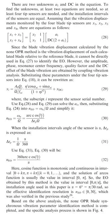
According to the principle of autoregressive method25:
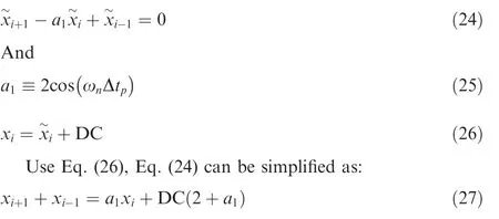
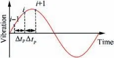
Fig. 3 Schematic diagram of a sinusoidal equidistant sampling point.
3. Numerical investigation
To verify the credibility and precision of the method. An academic mass-stiffness-damping mistuned blisk model without considering the coupling between blades is taken as example as shown in Fig. 5.
The differential equation of blade forced vibration with multi-degrees of freedom can be expressed as:
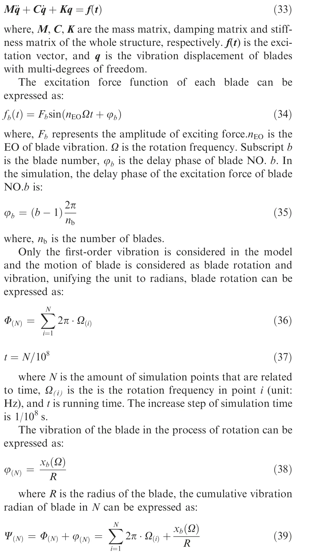
To simulate the arrival time which is captured by the tip sensor, the first point which has arrived to detective value is recorded in each revolution, the detective values are:

where φpis the phase between the blade and the tip sensor.
The four blades in this modal are numbered as B1, B2, B3and B4. The angle between the first tip sensor and B1is 0.The four blades are equally spaced. The vibration parameters of the simulated blades are shown in Table 1.
Gauss white noise with standard deviation of 10 is added to the simulated data,and blade B1is used as the reference blade.The amplitude of B2,B3and B4is calculated by the none OPR method. The coupling resonance section in the amplitude curve of each blade is intercepted and fitted by the LM method.The fitting results are shown in Fig.6(B2-1is the displacement of B2with B1as reference,and so on in this paper).
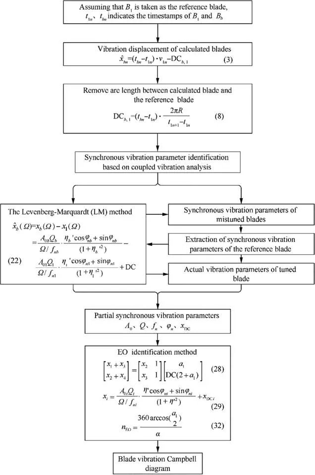
Fig. 4 Flow chart of blade synchronous vibration parameter identification without the OPR signal.
Table 2 lists the resonance parameters of the resonance peaks in Fig. 6 (the vibration amplitude curves of each blade contain two resonance peaks.It is listed order from left to right in Table 2 as Amax1and Amax2).
From the data in Table 2, it can be seen that there is a resonance with a center frequency of 95.03 Hz in the fitting results of B2and B3. Combining with the previous theoretical analysis, it can be determined that the resonance with a center frequency of 95.03 Hz is the resonance of B1. Because the coupling in the vibration amplitude of B4is so high that the resonance parameters of B1obtained from the fitting results of B4deviate greatly from 95.03 Hz,so it is unreliable to determine the resonance parameters of B4. Using the tuned blade resonance parameter identification method, the resonance parameters of B1obtained from the fitting results of B2and B3are re-fitted back to the coupling resonance section of B4for secondary fitting to obtain the actual resonance parameters of B4. Table 3 is the comparison between the theoretical real value and the identification results.
From Table 3, it is found that the identified synchronous vibration parameters are very close to the theoretical real values.Therefore,it can be said that the proposed method is feasible in blade vibration monitoring and parameter identification.
4. Experimental verification
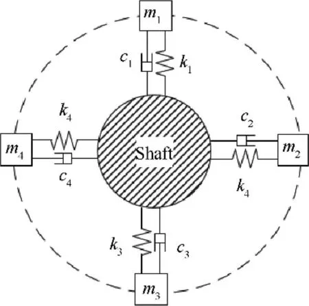
Fig. 5 Simulated blade model.
To verify the identification algorithm for blades synchronous vibration by the none OPR method, an academic straight blade test rig and a three dimensional real blisk test rig as well as a large industrial turbo fan is used. The details are as follows.
4.1. Experiments on straight blade test rig
4.1.1. Structure of test rig
The components are shown in Fig. 7. The test rig is mainly composed of the base, support (motor), operating platform,bladed disk, shield, permanent magnet excitation component and other auxiliary components.The case of the test rig is connected with the base by means of T-slot with bolts, and the motor wrapped in the case is fastened by three screws uniformly distributed in the circumferential direction. The shield mounted on the outside of the test impeller also serves as a sensor bracket. Five BTT sensor mounting holes are arranged in the circumference of the shield with an interval angle 6°. The top of the shield is equipped with 12 permanent magnet excitation component mounting holes. Each exciting component is embedded with a cobalt-based permanent magnet to provide exciting force. By adjusting the number and distribution of the components, experiments under several excitation combinations can be carried out.
The impeller consists of 32 blades with a diameter of 138 mm. An OPR groove and a balance groove designed for balancing the OPR groove are arranged on the upper part of
the impeller. In order to reduce the natural frequency of the blade so as to excite higher natural frequencies at lower rotational speeds, the blade is thinned locally at the root of the blade and the weight of the blade head is increased. At the same time,a counterweight hole is designed at the head of each blade. The natural frequency of the blade can be changed by the counterweight, and the mistuning characteristics of the impeller can be studied.
4.1.2. Analysis of experimental data
In this experiment,six exciting components are installed.Four BTT sensors sampling the arrival time series of each blade.The sampling frequency is 5 MHz, and the speed-up rate is 1 Hz/s during the sweeping frequency measurement. Taking the data measured by sensor No.1 as an example, the first four blades arriving at the sensor are numbered as B1, B2, B3and B4according to the time sequence,the corresponding relationship with the actual blades in the blade disc can be identified by Stack Plot,17,18all three experiments in this paper follow this numbering method and will not repeat it later. The vibration amplitude of B2, B3and B4calculated by the none OPR method with reference to B1in the speed range of 95-155 Hz is analyzed, as shown in Fig.8,B2-1,B3-1and B4-1respectively.

Table 1 Vibration parameters of the simulated blades.

Fig. 6 Fitting results of coupled resonance of simulated blades.

Table 2 Fitting parameters of coupled resonance of simulated blades.

Table 3 Comparison between set value and identification result.
As can be seen from Fig. 8, the blade resonance occurs when the rotation frequency is about 115 Hz (the blue circle is marked in the figure).This resonance curve is the superposition of the resonance of the reference blade and the calculated blade. The three resonance sections in the figure are fitted by the LM method.The fitting results are shown in Fig.9.Table 4 is the partial vibration parameters obtained by fitting.
Based on the data in Table 4 and the previous theoretical analysis, it can be concluded that the resonance with a center frequency of 113.22 Hz is the resonance of B1. Because the coupling degree in the vibration displacement of B2obtained by the none OPR method is so high that the vibration center frequency of B1obtained from the fitting results of B2deviate greatly from 113.22 Hz. Therefore, it can be judged that the harmonic resonance parameters of B2are also unreliable.The actual harmonic resonance parameters of B2can be obtained by using the tuned blade parameter identification method proposed above. Table 5 is the identification results of synchronous vibration parameters with none OPR method.
Using the EO identification method proposed in the article,the vibration parameters of the B1in Table 5 are substituted into the Eq. (28), and the vibration amplitude response curve of the B1under the sensor No.1 is obtained, as shown in Fig. 10.
Using the above method to analyze the data measured by the other three sensors, the vibration displacement curve of B1under the four sensors is obtained, and the EO calculated by the method proposed in this paper is 18,and then the identification of synchronous vibration parameters with the none OPR method is completed, and the identification results are shown in Table 6.
The identification results show that the natural frequencies of each blade are different,which indicates that the bladed disk is mistuned. Assuming that the reference blade(B1) is tuned,define the mistuning of blade as ωnc-ωnr, where ωncis the first-order vibration frequency of the calculated blade, and ωnris the first-order vibration frequency of the reference blade,then the mistuning of B2, B3and B4is 0.324 Hz, 19.098 Hz,26.496 Hz respectively.Figs.11 and 12 show the vibration frequencies and amplitudes of all blades obtained by the proposed method.
4.2. Experiments on twisted blade test rig
4.2.1. Structure of test rig
The High-speed twisted blade test rig consists of a base, support(motor),an operation platform,bladed disk,shield,cover and other components,as shown in Fig.13.Two rows of holes are arranged on one side of the shield for mounting the tip sensor, and one on the other side for mounting the tip clearance sensor. And on the top of the shield, a cover with diversion grids, where these diversion grids are used to simulate the vanes of turbine, when the bladed disk rotates, air is sucked into the diversion grids and discharged through the Vent holes at the bottom of the shield to exert exciting force on the blade.In addition,it is equipped with an OPR sensor and a sensor for measuring the axial vibration of the blade disc on the cover.The number of blades is 32, and the diameter of the impeller is 140 mm. This test rig can monitor the bend, lean, untwist,axial shift and tip clearance of blades at the same time, in this experiment, only the bend of the blade tip is measured.
4.2.2. Analysis of experimental data
In this experiment, four tip sensors synchronous sampling the arrival time series of each blade, and the sensor mounting angles between two adjacent sensors are all designed as 6°,the sampling frequency is 5 MHz, and the speed-up rate is 2 Hz/s during the sweeping measurement in the frequency range of 50-190 Hz. Taking the data measured by sensor No.1 as an example, Fig. 14 shows the vibration amplitude of the blade numbered B1, B2, B3and B4obtained by the method with OPR, and the harmonic resonance with center frequency about 170 Hz is selected as an example for analysis.
Use the GARIV-LM method16, the harmonic resonance section of sweep data is fitted with LM method,then the blade is operated at constant speed at the resonance center frequency, and the EO corresponding to the resonance is identified by GARIV method with the data of constant speed operation, Table 7 is the vibration parameters identification results.
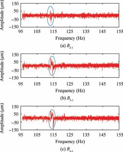
Fig. 8 Vibration amplitudes of straight blades calculated by none OPR method.
Choose B4as the reference blade, Fig. 15 shows the vibration amplitude of B1,B2and B3calculated with reference to B4,in order to compare with the traditional BTT method,the resonance with the center frequency of 170 Hz is also selected for analysis.
The LM method is used to fit the resonance section with center frequency about 170 Hz, the fitting results are shown in Fig.16,Table 8 is the partial vibration parameters obtained by fitting. And the resonance parameters like vibration amplitude,resonance center frequency,quality factor and the phase of each blade can be obtained by using the CVA method.Then, using the same method to analyze the data measured by the other three sensors, the vibration amplitude under the four sensors is obtained,and the EO identified by the proposed method is 12. This process is consistent with the analysis process of the previous experimental, and will not be described here. Table 9 shows the synchronous vibration parameters identification results.
Using the same method to analyze all harmonic resonances occurring during sweeping, and the corresponding frequencies and EO of each harmonic resonance are obtained. Fig. 17 is the Campbell diagram of B4.

Fig. 9 Fitting results of coupled resonance of straight blades.

Table 4 Fitting parameters of coupled resonance of straight blades.

Table 5 Identification results of straight blades resonance parameters by CVA method.
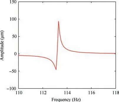
Fig. 10 Vibration amplitude of B1 under the sensor No.1.
From Tables 7 and 9, it can be seen that the identification results of the two methods are very close,the minimum relative error of blade natural frequency and amplitude identification is0.002% and 1.788%. The natural frequencies of the identified blade are also different, which provides experimental verification for the accuracy and applicability of this method in identifying vibration parameters of twisted blades.Figs.18 and 19 is the vibration frequency and amplitude diagram of all blades obtained by two methods.

Table 6 Identification results of straight blades synchronous vibration parameters.
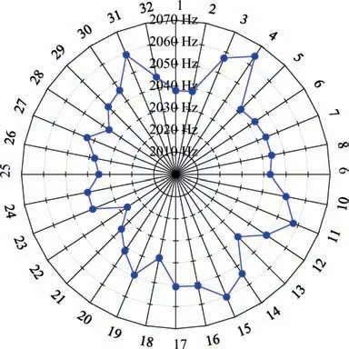
Fig. 11 Vibration frequency of all straight blades.
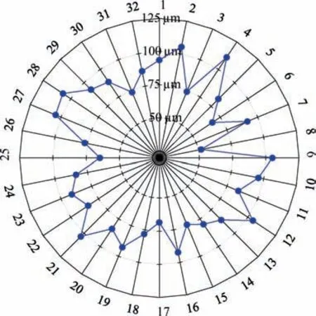
Fig. 12 Vibration amplitude of all straight blades.
Compared with GARIV-LM method, the result of proposed method is very close to it,but this method does not need OPR,so it saves cost and is more suitable for none OPR equipment such as aero-engine,and the identification process of this method is simple,it does not need constant speed operation to obtain EO, instead, the synchronous vibration parameters of blades can be identified by one sweep frequency measurement with less workload,in addition,the method can quantitatively identify the mistuning of blades and can be applied to real-time vibration monitoring.
4.3. Verification on large industrial turbo compressor
4.3.1. Monitoring objects and monitoring system
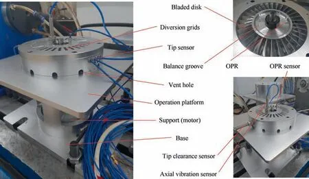
Fig. 13 Twisted blade test rig.
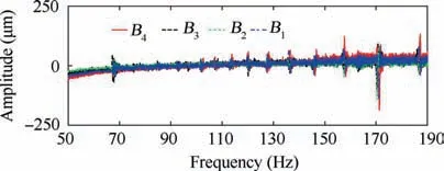
Fig. 14 Vibration amplitudes of twisted blades obtained by method with OPR.
In order to verify the applicability and reliability of the proposed method in real turbines, vibration monitoring of an axial compressor is carried out. The monitoring object is the last stage blade of an axial compressor. The number of blades and vanes are 36,31,and the diameter of impeller is 1.7 m.The vibration mode and natural frequency of the blade can be extracted by Finite Element Method (FEM), as shown in Fig. 20.
The monitoring system is composed of hardware and software.The hardware includes laser emitter,optical fiber sensor,photodetector and acquisition device. The optical fiber sensor used in monitoring is six channel focusing optical fiber sensor.The laser emitter provides 10 laser outputs, and the output optical power adjustment range is 0-1.2 W.The photodetector supports a maximum bandwidth of 150 MHz, the samplingmode is digital sampling with a maximum sampling frequency of 40 MHz. The software is a real-time monitoring software for blade vibration independently developed by our team,which includes three modules: data acquisition and recording,on-line analysis of blade vibration displacement and data postprocessing.

Table 7 Identification results of twisted blades synchronous vibration parameters by GARIV-LM method.
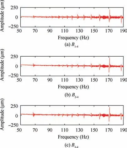
Fig. 15 Vibration amplitudes of twisted blades calculated by none OPR method.
Eight BTT sensors are installed in the casing arranged in two rows. Each row has four sensors distributed at an equal angle of 6°. The distance between the sensor tip and the blade tip is 2-3 mm,as shown in Figs.21 and 22.In addition,a OPR sensor is installed on the side of the driving shaft. The radial distance between the OPR sensor tip and the shaft surface is 2-3 mm. As shown in Fig. 23.
4.3.2. Vibration analysis
In the analysis with OPR,the OPR is taken as the reference of theoretical arrival time,and it is considered that the OPR does not vibrate when it rotates.Fig.24 shows the vibration amplitude curves of four blades under the sensor No.1, which are recorded as B1, B2, B3and B4respectively.
Use the GARIV-LM method,16the synchronous resonance parameters like vibration amplitude, resonance center frequency, quality factor and the phase are obtained by fitting harmonic resonance displacement with LM method, and the EO identified by GARIV method is 29, considering that the image of cos function image on [0,2π] is symmetrical with respect to x=π, it is known that the corresponding a1=2cos(nEOα) value of nEO=29 and nEO=31 is equal, in order to verify the reliability of the EO identified results,a high EO identification method based on sensor interpolation is used to verify the result, the identification result is 31, notice thatthe number of compressor vanes is 31,so EO is corrected to 31.Table 10 shows the synchronous vibration parameters identified by the GARIV-LM method.

Table 9 Identification results of twisted blades vibration parameters by CVA method.
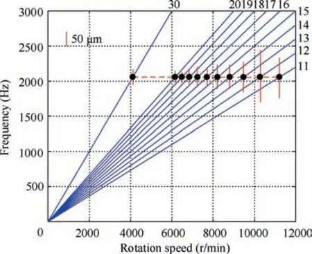
Fig. 17 Campbell diagram of B4.
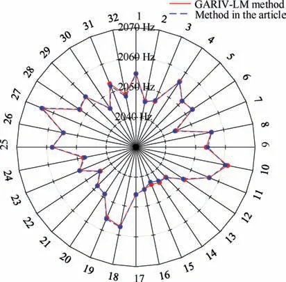
Fig. 18 Vibration frequency of all twisted blades.
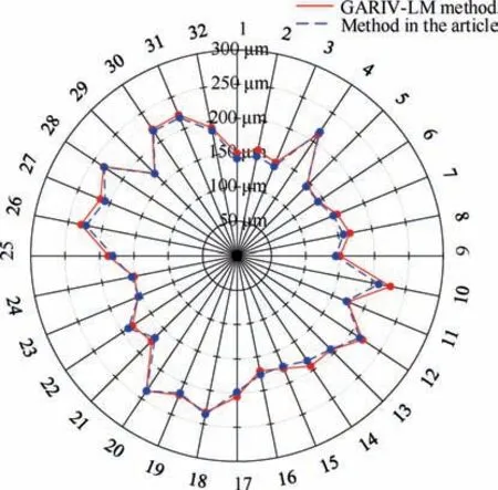
Fig. 19 Vbration amplitude of all twisted blades.
Similarly,the above four blades are analyzed by none OPR method, the vibration amplitudes of the other three blades were obtained with the B4as the reference blade. As shown in Fig. 25.
As can be seen from Fig. 25, there are two harmonic resonance peaks in each group of vibration amplitudes, one belongs to the calculated blade itself and the other belongs to the reference blade B4. The coupling resonance is analyzed using the method described above to separate the harmonic resonance parameters of each blade.
Fig. 26 is the fitting result of the coupled resonance in the vibration amplitude of B1, B2and B3with B4as reference respectively. The partial vibration parameters obtained by fitting are shown in Table 11.
From Table 11, the coupling resonance parameters of B1and B2both contain the center frequency of 8.28 Hz. So the resonance with a center frequency of 8.28 Hz is the resonance of B4. Using the tuned blade parameter identification method proposed above,the actual resonance parameters of B3can be obtained. Table 12 is the identification results of vibration parameters with none OPR method.
The same method is used to analyze the data of the other three sensors in the same row, and then the vibration parameters of each blade under each sensor are obtained. The EO is finally corrected to 31 by using the identification method mentioned above.Table 13 is a comparison of the vibration parameters of B4obtained by two methods.
It can be found that the vibration frequencies obtained by two methods are very close, and there is a little error in the amplitude. This is due to the following two reasons, on the one hand, because the blade mistuning is not obvious, when the two blades are tuned, the amplitude will be superimposed or cancelled while using the none OPR method, which makes the amplitude deviate from the actual amplitude;On the other hand, there is a certain vibration amplitude in non-resonance,which may be caused by speed fluctuation and measurement noise, when the vibration displacement is calculated by non OPR method, the vibration displacement at these nonresonance points will be superimposed or cancelled from the actual vibration displacement,which will also make the amplitude deviate from the actual amplitude.
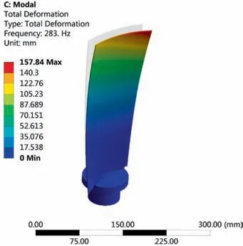
Fig. 20 The 1st modal of moving blade.
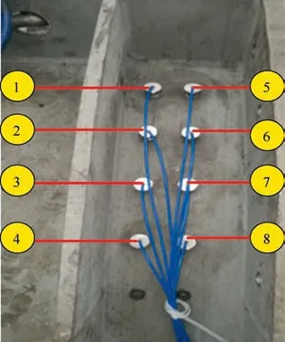
Fig. 21 Tip sensor layout.
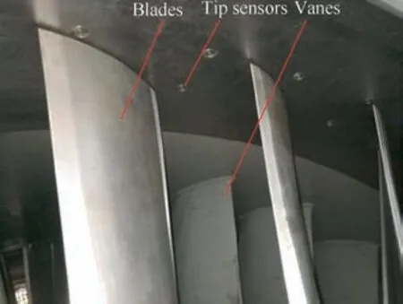
Fig. 22 Tip sensor installation diagram.
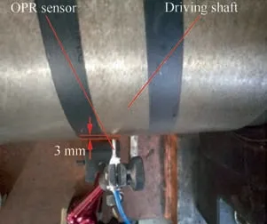
Fig. 23 OPR sensor installation diagram.
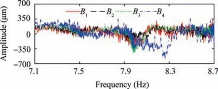
Fig.24 Vibration amplitudes of industrial turbo blades obtained by method with OPR.
However, the identification of vibration frequency is not affected by the mistuning characteristics of blades, and the experiment proves that the actual bladed disk is often mistuned, so the none OPR method can be used for blade vibration monitoring and vibration parameter identification to achieve the purpose of fault early warning. In addition, this method can also be used as an important means to detect blade mistuning,to evaluate the blade dynamic stress amplitude and to check the maintenance of operating rotor,which is of great significance to the safety evaluation of bladed disks. Fig. 27 is the first-order vibration frequency diagram of all blades in the last stage obtained by two methods. It can be seen that the first-order vibration frequency of 36 blades is different, which is the mistuned blade disk (see Fig. 28).
There is a deviation between the first-order vibration frequency measured by BTT and calculated by FEM (relativeerror is about 9.3%),this is influenced by many uncertain factors. Such as the error between the finite element model and the actual experimental model.

Table 10 Parameter identification results of industrial turbo blades by GARIV-LM method.
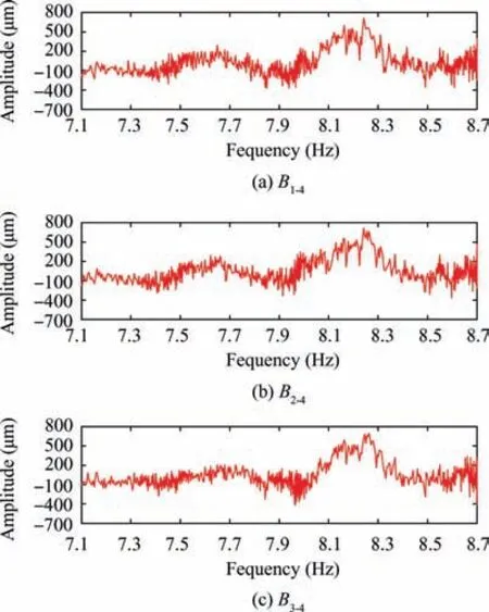
Fig. 25 Vibration amplitudes of industrial turbo blades calculated by none OPR method.

Fig. 26 Fitting results of coupled resonance of industrial turbo blades.

Table 11 Fitting parameters of coupled resonance of industrial turbo blades.

Table 12 Identification results of industrial turbo blades vibration parameters by CVA method.

Table 13 Comparison of vibration parameters identification results of B4 by two methods.
5. Conclusions
The paper presents a none OPR BTT method to measure blades vibration and detect the degree of blades mistuning.The method takes any blade as the reference blade to calculate the other blades vibration through the reference blade. The principle of the method is to identify the blade vibration parameters based on the mistuning characteristics of blades.The method is verified by numerical simulation and experimental work based on three different scale test rig. The conclusions are as follows:
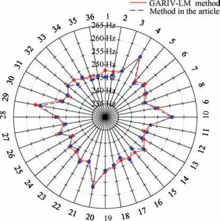
Fig. 27 Vibration frequency of all industrial turbo blades.
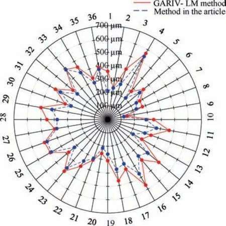
Fig. 28 Vibration amplitude of all industrial turbo blades.
(1) Through numerical simulation, the feasibility and accuracy of the proposed method are verified.
(2) Through two academic test rigs,the validity and feasibility of the method in vibration monitoring and parameter identification of straight blades and twisted blades are verified respectively.
(3) The vibration monitoring of axial compressor blade is carried out, and the monitoring data is analyzed by two methods respectively.The results show that the proposed none OPR method can accurately identify the synchronous vibration parameters. The frequency identification relative error between the none OPR method and the GARIV-LM method with OPR is less than 0.06%.
Acknowledgements
The work described in this paper was supported financially by Natural Science Foundation of China (Nos. 51775030,91860126) and the Fundamental Research Funds for the Central Universities(No.BHYC1703A).These supports are gratefully acknowledged.
 CHINESE JOURNAL OF AERONAUTICS2020年7期
- CHINESE JOURNAL OF AERONAUTICS的其它文章
- An experimental method for squealer tip flow field considering relative casing motion
- Highly efficient computation method for hazard quantification of uncontained rotor failure
- Optimal motion cueing algorithm for accelerating phase of manned spacecraft in human centrifuge
- Effective control allocation using hierarchical multi-objective optimization for multi-phase flight
- Fault-tolerant control and vibration suppression of flexible spacecraft: An interconnected system approach
- Trajectory tracking control of a VTOL unmanned aerial vehicle using offset-free tracking MPC
