Optimal motion cueing algorithm for accelerating phase of manned spacecraft in human centrifuge
Ali MAHMOODI, Isooda KAZEMI
Department of Aerospace Engineering, Science and Research Branch, Islamic Azad University, Tehran 1477893855, Iran
KEYWORDS Accelerating phase;Human centrifuge;Manned spacecraft;Optimal motion cueing;Specific force
Abstract This paper presents a novel optimal Motion Cueing Algorithm (MCA) to control the rotations of a Human Centrifuge (HC) and achieve the best simulation of a SpaceCraft (SC)motion. Relations of the specific forces sensed by astronauts of the SC and the HC have been derived and linearized. A Linear Quadratic Regulator (LQR) controller is implemented for the problem which tends to minimize the error between the two sensed specific forces as well as control input in a cost function.It results in control inputs of the HC to generate its sensed specific force as close as possible to the one in the SC. The algorithm is implemented for both linearized and nonlinear portions of a US space shuttle mission trajectory as a verification using MATLAB.In longitudinal direction,the proposed MCA,works well when the acceleration is less than 2g in which the tracking error does not exceed 12%.In lateral direction the tracking is much better even in nonlinear region since the error remains less than 7% for tilting up to 50°. Finally, the effect of weight matrixes in the LQR cost function on overall weight and power of the HC motion system is discussed.
1. Introduction
The astronauts of manned SpaceCraft (SC) are exposed to extreme condition during lift off because of both high sustained acceleration and rotation while tilting to enter the orbit.This is also repeated in reentry Phase due to big deceleration.Upward climbing of an SC is one of the most challenging steps of its mission due to the large amount of acceleration exerted on its astronauts. Since the acceleration has a considerable duration,it may be harmful for the astronauts especially when combined with the rotation of the SC during its turning into orbit.Therefore,it is necessary for the astronauts to experience such accelerations and rotations frequently in a simulator prior to gearing up the main mission. Their ability to tolerate such adversity and perform tasks can be examined in a Human Centrifuge (HC), a device established to simulate sustained accelerations of combat aircraft and spacecraft. Fig. 1 shows an HC, which is a 3DoF device capable of producing three rotations in yaw, pitch, and roll directions. It consists of a rather long horizontal arm which rotates around a vertical Z axis.At the end of the arm,a gondola,which is assembled in a gimbal to produce roll and pitch angular movements,is located.A counterweight on the other side balances the weight of the arm and gondola. The astronauts’ seats are placed in the gondola analogous to those of the SC. All components of angular velocities in roll, pitch, and yaw directions can be controlled to produce any sets of desired accelerations in desired directions for the astronauts. The main part of specific force imposed on astronauts is produced by centrifugal effect due to the rotation of the arm around the Z axis (yaw). The force vector established on an astronaut in SC can be reproduced in the HC by controlling the orientation and angular velocity of the gondola.
The problem of Motion Cueing Algorithm(MCA)is to find the desired amounts of the angular velocities and orientations of the gondola to make the closest sensation of specific force experienced by the astronaut inside the HC to the one inside the SC. The specific force is defined as1:

which is the difference between the acceleration and the normalized gravity force.On quantitative grounds,the best simulation is equivalent to the condition in which the error between the sensed specific forces of the two astronauts reach zero.The specific force is the resultant acceleration which can be sensed in human beings by means of otolith organ located in the inner ear.1In fact,the acceleration sensor of the body cannot distinguish between the translational and gravitation accelerations and only can sense the resultant of the two accelerations.
The earliest research regarding the mechanism of sensing the sustained acceleration in a human being inside an HC was published in 1965.2Further studies were published by Burton et al. in which the tolerance limits of humans against sustained acceleration had been examined.3They found the reaction between the magnitude of acceleration and its duration that body can tolerate, and also determined the reaction of body to high-g acceleration is a case dependent issue.Albery and Martin developed an experiment-based study in the HC to determine the causes of Space Motion Sickness (SMS).4Furthermore, Forster et al. showed that the tolerance of high-g depends on age.5One of the initial algorithms for controlling the angular motions of a 3DoF human centrifuge was developed in Development Center’s Dynamic Flight Simulator(DFS).6,7Its goal was to create a sense of angular motion realism for the DFS pilot. The algorithm was produced by the combination of linear and angular cues. The authors derived appropriate angular cues of DFS to impose appropriate sensation of angular velocity in a total g-force environment and they simply designed an elastic control system to follow the cues.Chen and Reperger derived the kinematics and dynamics of a 3DoF HC and utilized feedback linearization method to control its motion.8Kvrgicn et al.developed an algorithm to control the angular velocity of main arm of the HC considering the torque limitations of the actuating system.9The algorithm works in such a way that the onset rate of the absolute acceleration is constant.
The problem of matching the sensed specific forces of a traveler in the HC to the one in the SC can be considered as an optimal control issue in which the difference between the two sensations should be minimized.Essentially,it holds a performance index, which contains that difference as an error as well as the control input. This structure leads to an algorithm known as optimal MCA. The optimal MCA can be broadly found in literatures for aviation applications.The earliest studies are found in the works of Sivan et al.in 1982.10They build up the first structure of the MCA as a Linear Quadratic Gaussian(LQG)problem and considered the motion of actual vehicle as a random input modeled with white noise. They also represented the kinematics of the motion system,the dynamics of specific force, and vestibular sensation as a linear model.Another assumption considered was decoupling the motion into four separate channels including pitch-surge, roll-sway,heave and yaw. Reid and Nahon developed an algorithm,combining it with the linear models of motion sensation in pilot’s head reference frame and made several experiments in University of Toronto Institute for Aerospace Studies(UTIAS) research flight simulator.11Wu reformulated the optimal MCA by transforming the pilots head axes to the simulator body axes. They also rehabilitated the input signals of longitudinal and lateral motions.12Telban et al. implemented several research regarding MCA which had been performed prior 2005 in aviation application.13,14No distinguished works regarding optimal MCA can be found after 2005 other than some improvements in coordinate transformations. We transformed the workspace coordinates of the motion system into the actuator space and developed the optimal MCA.15Subsequently, they profoundly guaranteed the motion system not exceeding its physical constrains than the conventional optimal MCAs and the maximum capacity of the motion system performing large movements was gained.
All the above mentioned studies are applied to aircraft motion simulation in motion based flight simulators and the capacity of the HC to perform optimal MCA was neglected by researchers. The users of the HC have always used to passively utilize it to produce sustained accelerations; albeit, in case a proper MCA in addition to a servo drive system is applied, it can actively simulate the entire climbing phase of a spacecraft. Utilization of servo drive system to HS instead of traditional drive system, helps it follow a specified control input. This paper tends to achieve this goal by the implementation of an optimal MCA to the HC. However, there are essential differences between the aircraft and spacecraft simulators.The main differences in the specifications of a spacecraft in comparison with an aircraft are: (A) Substantial extent of acceleration within great duration of time and (B) Quasivertical position in flight instead of quasi-horizontal. (C) The acceleration in conventional manned spacecraft varies between g and 3 g while in the commercial aircraft hardly reaches g.11Hence, the only way to produce such a broad gamut of accelerations in an SC simulator is to employ centrifugal force which causes the structure of the simulator to be quite different from those applied in aviation from the modeling point of view. The centrifugal force has an absolute nonlinear nature.Thus,adequate attention is a requirement in the determination of linearization limits.
The latter parts of this paper consist of the five following sections. Section 2, deals with the modeling of the specific forces imposed on astronauts in the HC and SC. At the end of this section,the obtained models are linearized and normalized to be comparable with each other. In Section 3, the motion sensation’s dynamic model equations in human being are derived in linear form and augmented to specific force models obtained in Section 2. Furthermore, in Section 4, the optimal MCA is developed for the problem to minimize the motion sensation error between the SC and HC as well as the control inputs. In Section 5, the algorithm is applied on a US space shuttle model with a specified mission profile in MATLAB environment. Finally, in Section 6, the conclusions are integrated and summarized and practical considerations regarding choosing weight matrices are discussed.
2. Modeling of specific force in HC and SC
2.1. Specific force in HC
Otolith is the organ which senses the specific force in human being. It is located inside the inner ear almost in the middle of the head. It is assumed that the HC caries only one astronaut and their seat is so situated to have their head approximately in the center of the rotation of the gondola (see Fig. 2). Hence, the head remains almost moving-free with respect to the center of the rotation and the translation of the head is neglected while the gondola rotates about roll and pitch axes. Consequently, the translational accelerations of the otolith can be ignored. The specific force in Eq. (1)can be extended as below:

in which a is the translational acceleration, ω is the angular velocity, and R is the vector connecting the z axis of the HC to astronaut’s head.The superscript‘‘b”denotes‘‘body frame”which is attached to astronaut’s head with unit vectors i,j,k in x, y, z directions respectively (see Fig. 2). The net angular velocity of the gondola can be written as:

whose components are shown in Fig. 2 in the coordinate frame attached to the HC.
The transformation between the two frames depicted in Fig. 2 is as below:
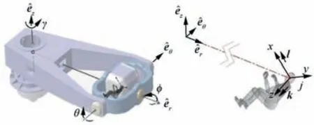
Fig 2 Coordinate frame attached to the HC.
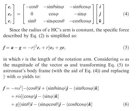
For implementation of the linear optimal MCA to the HC,Eq. (6) should be linearized in the vicinity of its average operating point.The magnitude of acceleration in a manned spacecraft often varies from g to 3 g. Fig. 3 illustrates the acceleration graph of the US Discovery space shuttle, in STS-121 mission along its longitudinal body axis for instance.16The propulsion system of the SC should carefully be programed to make the sustained acceleration of the SC not exceed the toleration margins of the astronauts17.
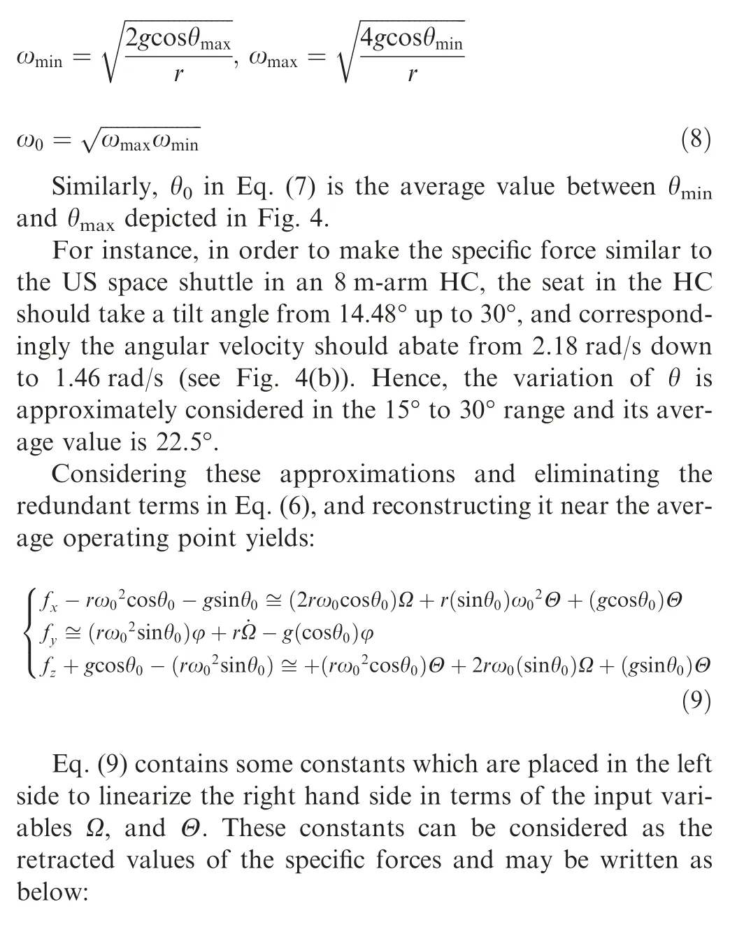
The specific force is imposed on astronaut’s body through their seat. In a conventional air vehicle like an aircraft, on one hand, the seats are upright, since its attitude is quasihorizontal during flight. In some spacecraft like the US Shuttle, on the other hand, the seats will be horizontal since the attitude of the spacecraft is quasi-vertical (see Fig. 4(a)).Therefore, astronauts lay on their backs during the SC lift off.This position helps the astronauts tolerate the tremendous acceleration imposed on their body. Ergo, the specific force introduced on their backs varies from 2 g to 4 g according to the Eq. (1) and the graph in Fig. 3. Note that not in all of manned spacecraft, the astronauts have this kind of posture(like the Chinese spacecraft ‘‘Shenzhou 5” in which the seats has a back corner);however,the proposed algorithm is general and the initial orientation of the seat can be taken into the account in every spacecraft. This specific force should be reproduced in the HC by combining centrifugal and gravity forces. This will be obtained by the adjustment of the arm’s angular velocity as well as the tilt angle of the gondola. (see Fig.4(b)).Fig.4(b)demonstrates the maximum and minimum angular velocities of the arm and the corresponding tilt angle of the seat to produce this range of accelerations imposed on the traveler by the back of their seats.
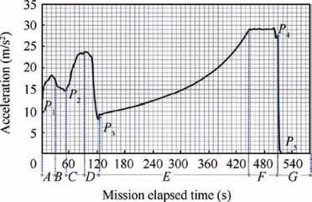
Fig. 3 Longitudinal acceleration in US Discovery space shuttle,in STS-121 mission.

Fig 4 Position of astronauts in SC and corresponding position in HC for the minimum and maximum amounts of specific forces.
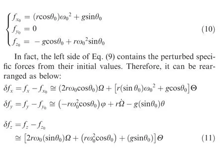
To reproduce such a specific force in the HC,the tilting of the gondola in θ direction would be enough;hence,the roll angle of the gondola φ is deliberated to benear zero.Thus,the terms sin φ and cosφ in Eq.(6)can be replaced by φ and 1 respectively.The angular velocity value ω and the tilt angle θ can be perturbed by their average values ω0and θ0respectively:
ω=ω0+Ω, θ=θ0+Θ (7)
in which ω0is the average value between the two limits ωminand ωmaxdepicted in Fig. 4, and Ω and Θ are the perturbed values. Ω and Θ are considered as the input variables for the HC model. ωminand ωmaxcan be simply calculated from the geometry depicted in Fig.4,and consequently ω0can be determined by calculating the average of ωminand ωmax:
2.2. Specific force in SC
In this section the equations describing the specific forces imposed on astronauts of the SC are derived based on the following assumptions:
(1) The spacecraft travels in vertical plane.
(2) In the acceleration graph, only the part with the monotonic increase in the acceleration is taken into the account. This portion is referred to as the accelerating phase. For the STS-121 mission, this range is between the points P3and P4in Fig.3,in which the acceleration monotonously increases from g to 3 g in an almost 5 min timespan. In the US space shuttle it takes place from solid rocket separation up to the main engine cutoff,during which the astronauts experience enormous velocity due to the lack of drag force and the longest sustained acceleration as well.
(3) The gravity acceleration g is assumed to be constant during accelerating phase.
(4) The pitch angle increases from 90°to almost 110°during the accelerating phase (see θ and λ in Fig. 5).
(5) λ changes from 0° during launch to 90° in orbit turning through the mission.
(6) The SC has negligible roll during mission and the direction of rotation is in a way that the attitude of the astronauts change from horizontal to upside down vertical position while the shuttle gradually changes its attitude to orbit turning (see Fig. 5).
(7) The longitudinal component of the acceleration dominates its lateral component since the thrust is toward longitudinal direction.
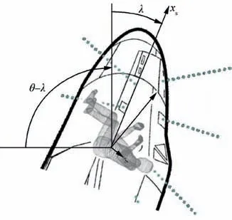
Fig. 5 Pitch angle of US space shuttle and astronauts’ attitude during accelerating phase.
Considering the body coordinate frame attached to the astronaut as the one depicted in Fig. 5, the specific forces in x and z directions can be stated as below:

(Note that xsin Fig. 5 is identical to x. The subscript s,stands for spacecraft) Based on assumption 6), we take az≅0;thus,the only component of the acceleration in z direction is due to rotation of the SC. Hence, Eq. (12) is reconstructed as follows:

in which Rsis the longitudinal distance from the CG point of the SC to the astronaut’s head (see Fig. 5).
Among the two variables θ and λ in Fig. 5, λ is preferable for the linearization purpose.Based on the ablove assumption 4), it is possible to consider the approximations sinλ ≈λ and cosλ ≈1 and rewrite the linearized form of Eq. (13) as below:

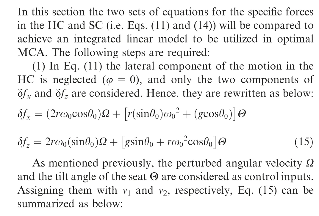
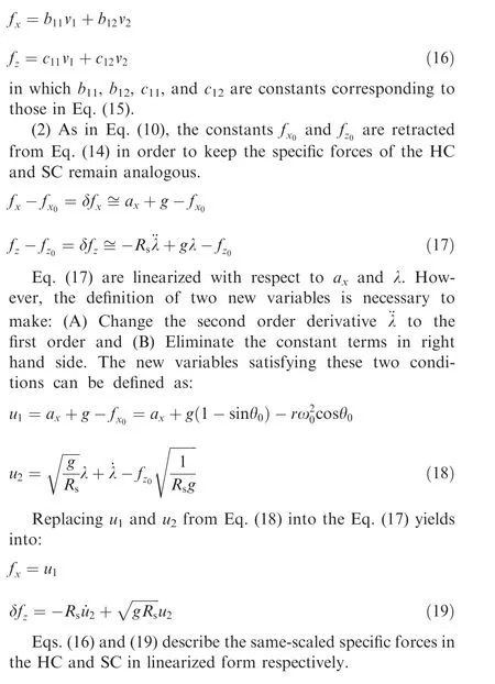
2.3. Comparison between specific forces in SC and HC
3. Motion sensation dynamics in SC and HC
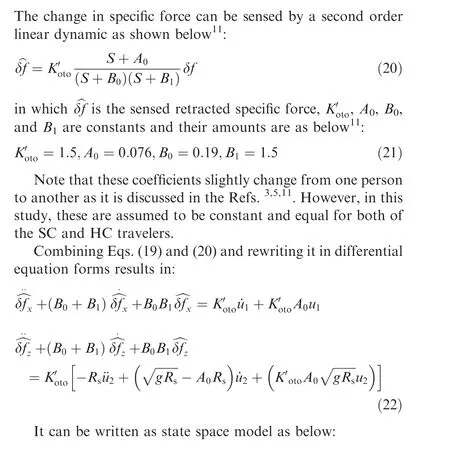
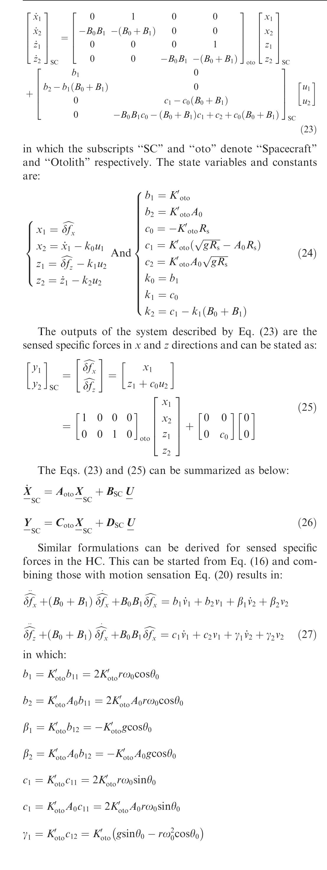
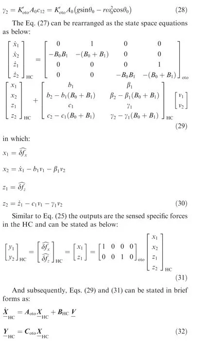
in which the subscript ‘‘HC” denotes human centrifuge. The sensation equations for both the astronauts inside the SC and the HC are derived and summarized as Eqs. (26) and(32). Note that in deriving state space Eqs. (23) and (29) the predefined functions of MATLAB cannot be used.These functions, namely ‘‘tf2ss”, automatically divert the differential equation form to the state space form with a random choice of states. Accordingly, the state matrixes ‘‘Aoto” in Eqs. (23)and (29) would not be identical despite they are required to be so. (The reason will be proposed in Section 4). Hence, the state variables are chosen in a way to achieve this end.
4. Development of linear optimal MCA
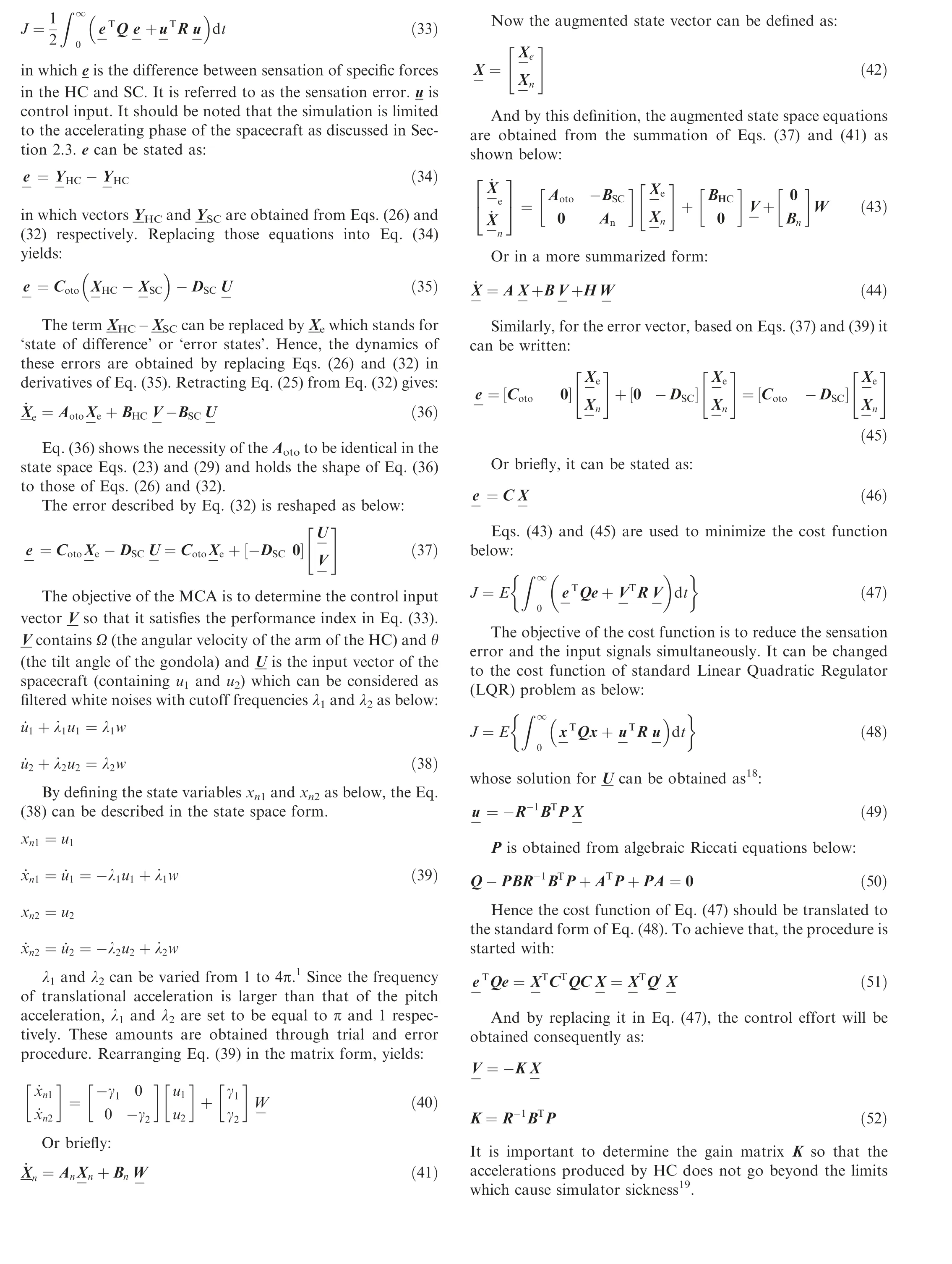
The main aim of simulating the motion of the manned SC by means of the HC is to close the sensed specific forces of astronaut inside the HC to the one inside the SC.This can be set up as a classic optimal control problem which attempts to minimize the performance index containing the quadratic form of the difference between the two sensations as well as control inputs. This performance index can be considered as below:
5. Simulations
It is chosen in a way that the majority of the penalty is applied to decrement of the sensation error rather than the input signals.
Depicted in Fig.6 is the longitudinal acceleration and pitch angle of the Discovery Space Shuttle in STS-121 mission in duration ‘‘E” of Fig. 3.
Fig.7 shows the inputs of the HC,ω,and θ which are angular velocity of the arm and the tilt angle of the gondola respectively.Since the motion system needs to track these inputs,this kind of control inputs should be applied by a servo drive system.
Fig. 8, on one hand, demonstrates the longitudinal specific forces exposed to the astronauts of the SC and HC in both nonlinear and linear models. It shows good coherence when compared with each other. In nonlinear model, the difference of the two accelerations increases as the acceleration of the SC increases. It is due to nonlinear behavior of the HC’s centrifugal force with respect to its angular velocity ω. Fig. 9, on the other hand, shows the lateral components of the specific forces in nonlinear and linear model which both seem consistent. (Note that in Figs. 8-11 the upper case F and the lowercase f stand for specific force and sensed specific force respectively).
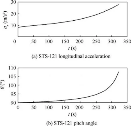
Fig. 6 Longitudinal acceleration and pitch angle of US space shuttle in accelerating phase.
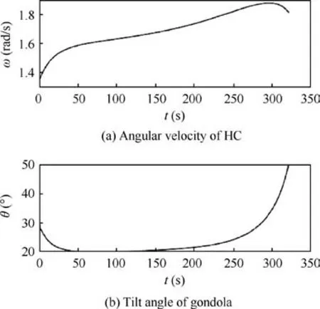
Fig. 7 Inputs of HC.
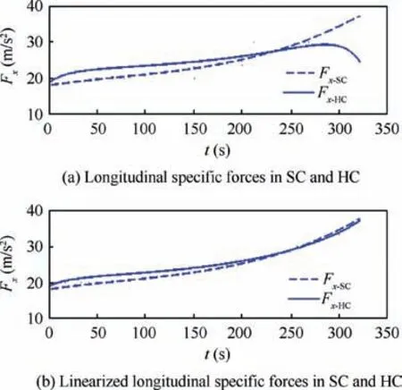
Fig. 8 Specific forces of SC and HC in longitudinal direction.
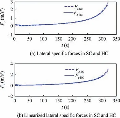
Fig. 9 Specific forces of SC and HC in lateral direction.
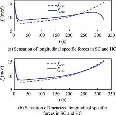
Fig. 10 Sensed specific forces of SC and HC in longitudinal direction.
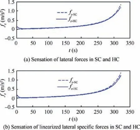
Fig.11 Sensed specific forces of SC and HC in lateral direction.
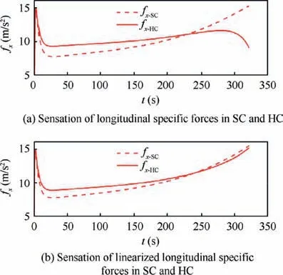
Fig. 12 Longitudinal sensed specific force with Q and R of Eq.(57).
Figs.10 and 11 show the sensed specific forces corresponding to those depicted in Figs. 8 and 9 respectively. The sensed specific forces show better matching than the pure specific forces of Figs. 8 and 9 since the performance index of Eq.(47) directly tends to decrease the difference between the sensed specific forces. In greater amounts of acceleration, the MCA tends to diverge in nonlinear model because of the nonlinear behavior of centrifugal force in the HC.
Since the selection of main drive for rotating the massive arm of the HC is a big challenge20, the decrement of angular acceleration of the arm will be very beneficial from manufacturing point of view. Increasing the diagonal elements of matrix R in Eq. (56) moderates the power supply capacity.Here a change is applied on the Q and R matrixes in Eq.(56) for instance and some results are compared with those in section 5:

This weakens the control inputs and permits larger sensation errors in comparison with the case with the Q and R of Eq. (56). The following graphs show the sensations of the specific forces in longitudinal direction, the tangential forces(fy) and the angular acceleration (which are representatives of the structural forces).
Utilization of less powerful actuators causes a larger difference between the specific forces sensed by astronauts of the CS and the HC as those shown in Fig. 12 when compared with those of Fig.10.However it is more beneficial since it produces a very smaller sensed tangential force and the angular acceleration (see Figs. 13 and 14). Fig. 15 demonstrates the control inputs of the two cases in the beginning instants of accelerating phase and it is obvious that case 1 contains significantly larger accelerations in rotation of both the arm and the gondola.Hence, changing the Q and R matrixes from those of Eq.(56) to those of Eq. (57); on one hand, abates the force sensation in longitudinal direction, but on the other hand, both eliminate the tangential false cue and decreases the power unit and structural capacity. This consequently decreases the weight and cost of the HC. In practice, the selection of the matrixes Q and R is based upon a compromise between these two extremes and practical deliberations such as weight,power supply,and cost should be considered in designing and manufacturing of the HC.
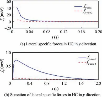
Fig. 13 Tangential sensed specific force with Q and R matrixes in Eq. (56) (case 1) and Eq. (57) (case 2).
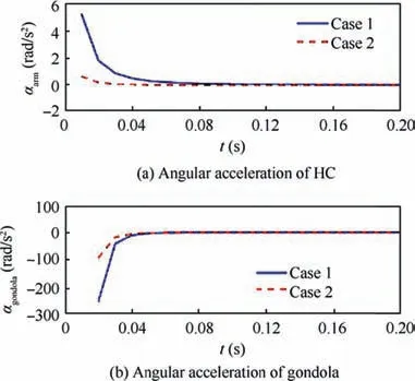
Fig. 14 Angular acceleration of arm of HC with Q and R matrixes in Eq. (56) (case 1) and Eq. (57) (case 2).
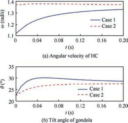
Fig. 15 Input signals for HC with Q and R matrixes in Eq. (56)(case 1) and Eq. (57) (case 2).
6. Conclusions
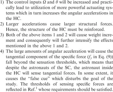
In this paper an MCA is proposed to derive the motion commands of a human centrifuge for optimum simulation of astronaut’s sensation of specific force in a spacecraft during acceleration. The algorithm can also be used for deceleration phases (as the one occurs in reentry phase of a spacecraft)when the decelerating profile is available. Figs. 6-11 in previous section show that the proposed algorithm works well in accelerating phase of the US space shuttle as an instance. It tends to diverge in longitudinal mode when the difference between the minimum and the maximum accelerations goes beyond g. In this region the sensation error is less than 12%(see Fig. 10), which will satisfy the requirements of training goals in some extent. The divergence in high accelerations is due to nonlinear nature of the centrifugal force which is proportional to the square of angular velocity. In lateral mode(i.e.in z direction)the algorithm works very well in both linear and nonlinear models, and the tracking is much better even in nonlinear region. In that region the error of tracking is less than 7% (see Fig. 11). The algorithm starts to diverge only in high tilt angles (more than 50° as can be seen in Fig. 7)and it is more beneficial than expected.However,it is expected to be diverged in the large tilt angles (for λ >120°). It is possible to increase the accuracy of the algorithm by increasing the diagonal elements of the matrix Q in comparison with diagonal elements of the matrix R in Eq. (47). This amplifies the penalty of error difference than the input limitation. This strategy has the following limitations in practice:
 CHINESE JOURNAL OF AERONAUTICS2020年7期
- CHINESE JOURNAL OF AERONAUTICS的其它文章
- An experimental method for squealer tip flow field considering relative casing motion
- A novel none once per revolution blade tip timing based blade vibration parameters identification method
- Highly efficient computation method for hazard quantification of uncontained rotor failure
- Effective control allocation using hierarchical multi-objective optimization for multi-phase flight
- Fault-tolerant control and vibration suppression of flexible spacecraft: An interconnected system approach
- Trajectory tracking control of a VTOL unmanned aerial vehicle using offset-free tracking MPC
