Trajectory tracking control of a VTOL unmanned aerial vehicle using offset-free tracking MPC
Tayyab MANZOOR, Yuanqing XIA, Di-Hua ZHAI, Dailiang MA
School of Automation, Beijing Institute of Technology, Beijing 100081, China
KEYWORDS Autonomous flight control;Model Predictive Control(MPC);Time delays;Trajectory tracking;Unmanned Aerial Vehicle(UAV)
Abstract Designing a stable and robust flight control system for an Unmanned Aerial Vehicle(UAV)is an arduous task.This paper addresses the trajectory tracking control problem of a Ducted Fan UAV(DFUAV)using offset-free Model Predictive Control(MPC)technique in the presence of various uncertainties and external disturbances. The designed strategy aims to ensure adequate flight robustness and stability while overcoming the effects of time delays,parametric uncertainties,and disturbances. The six degrees of freedom DFUAV model is divided into three flight modes based on its airspeed, namely the hover, transition, and cruise mode. The Dryden wind turbulence is applied to the DFUAV in the linear and angular velocity component.Moreover,different uncertainties such as parametric,time delays in state and input,are introduced in translational and rotational components.From the previous work,the Linear Quadratic Tracker with Integrator(LQTI)is used for comparison to corroborate the performance of the designed controller. Simulations are computed to investigate the control performance for the aforementioned modes and different flight phases including the autonomous flight to validate the performance of the designed strategy.Finally, discussions are provided to demonstrate the effectiveness of the given methodology.
1. Introduction
Unmanned Aerial Vehicles (UAVs) have gained a lot of importance in the present society due to their applications in both civilian and military fields.1Vertical Take-off and Landing (VTOL) UAVs have numerous advantages. Due to takeoff and landing ability, they do not require a runway while maintaining a high level of aerodynamic efficiency.2Moreover,they can easily monitor from a hovering view, which is not possible for most fixed-wing UAVs. However, UAVs such as rotary wing UAVs are not suitable in crowded urban areas because their blades are exposed.For safety purposes,Ducted Fan UAV(DFUAV)can be utilised since its blades are located inside the duct.3,4There is a thruster called fan,responsible for minimising the rotation of the body by a resultant torque.5Moreover, the fan generates more thrust than an open rotor for the same blade size.6These UAVs are also significant due to the smaller size. Furthermore, they have a larger static thrust while taking off,which produces higher lift.These vehicles are endowed with thrust vectoring capability that can provide both a net torque and a force for the aerial vehicle frame.7Also,this vectored thrust capability is responsible for enabling the transition to and from cruise flight.8
Various control techniques have been adopted over the years to solve the trajectory and attitude control problem of a VTOL UAV,which involves position tracking for outer loop and attitude tracking for the inner loop.9Jeong et al.proposed a position and attitude tracking control system using Linear Quadratic Tracker (LQT) and Linear Quadratic Tracker with Integrator (LQTI) for DFUAV under different flight conditions. The simulations were performed using different flight modes. Furthermore, controller effectiveness was validated through waypoint navigation under wind turbulence.10However,only the linear velocity component is utilised for the wind turbulence model,and model uncertainties are not considered.Furthermore, the PID controller is used for position tracking,and LQTI for attitude control and no state or disturbance observer is used to estimate the external disturbances. Raffo et al.presented a control strategy where State Space Predictive Control with Error model (E-SSPC) is used for trajectory tracking and nonlinear H∞controller for attitude control.11While its tracking performance is good, it does not have a good response under sustained disturbances.To overcome this problem, integral predictive control and H∞control are applied to a quadrotor UAV for trajectory tracking and attitude control.12It is a useful technique for achieving robustness, but it does not perform well under varying disturbances.Also,due to integral action,it can lead to slower system response, just like LQTI. Ma et al. researched trajectory tracking control and attitude control using MPC and Active Disturbance Rejection Control (ADRC) for quadrotor UAV, where MPC is used for trajectory tracking, and ADRC is used for attitude control.13An Extended State Observer(ESO) is applied to estimate the disturbances. It has excellent tracking and robust performance but has certain drawbacks.First, it involves feed-forward control, where it is challenging to get optimised performance. Second, lumped disturbances are considered,including parametric uncertainties.MPC based trajectory tracking and attitude control of tiltrotor tricopter VTOL UAV was presented in Ref.14Inner loop is stabilised through MPC, and the outer loop is controlled by PID. The simulations were executed using the hover mode after applying a trim analysis. However, neither uncertainties nor external disturbances are considered. Emami and Rezaeizadeh proposed two modified MPC based trajectory tracking and attitude control schemes for DFUAV.15While several issues were addressed,such as non-minimum phase behaviour,input delays, and actuators’ deflection, state delays are not considered. Furthermore, none of the above-mentioned approaches addressed transition flight. Various flight transition methodologies for trajectory tracking of VTOL aircraft have been presented in recent years. Govdeli et al. presented a nonlinear unsteady aerodynamic model coupled with 3-DOF quadplanes to control the transition flight between hover and steady level flight.16Two variants of the quadplane (pusher and tilt-rotor)are considered to investigate the controllability of altitude,attitude and forward speed. PID controller was employed to produce control inputs. Li et al. proposed a nonlinear robust control technique for a tail-sitter aerial vehicle to deal with the flight transition control.17The presented framework is based on nominal H∞controller and a disturbance observer.Parametric uncertainties, external disturbances, and nonlinear terms are considered. Simulation results demonstrated better control performance as compared to standard H∞controller.Oosedo et al. designed two different transition flight methodologies from the hovering to level flight for the quadrotor tail-sitter UAV.18The first technique was implemented by minimising the thrust power during the transition, and the second was achieved by maintaining the vertical force component equal to gravitational force even when the attitude of the aircraft changed. However, motor delays, the inertia moment of the vehicle, and external wind effects are not considered. In all the flight control techniques for trajectory tracking,10-14,16-18time delays are not considered.
MPC is an advanced optimal control strategy based on the receding horizon. It can handle Multi-Input Multi-Output(MIMO), nonlinear, and switching systems with different delays and can enforce soft and hard constraints,unlike many other control strategies.19Another feature of MPC is its ability to compensate model uncertainties and external disturbances while maintaining robustness. MPC problem was used earlier in the reference tracking or servo problem, which deals with either the initial state problem or rejection of stochastic disturbances.A further extension of this was a robust servo problem where a free-offset tracking was achieved under model mismatch and disturbances. However, it is not easy to implement MPC due to the tracking error fed into servo compensator.This strategy leads to a similar windup problem,which is common in PID, where a separate anti-windup mechanism is required. This issue can be solved through a state estimator.20Furthermore, the offset-free MPC provides a method when disturbances are generated by arbitrary, unstable dynamics.21In the recent past,an issue of MPC has been its higher computational cost and the unavailability of customised numerical solvers, which made it challenging to deploy in fast processes.But,due to advancements in both hardware and the numerical solvers,MPC can be applied to a variety of fields such as aerospace,automotive,and electronic systems.22To enable MPC in real-time processes for industrial applications, the quadratic programming must be embedded in the system.The procedure should be fast enough for it to find a solution with short sampling time and by simple embedded system. Several online computational algorithms exist in the literature, active-set methods,23interior-point method,24and fast gradient method.25Another challenge with traditional MPC is online computation to solve control action, which makes it challenging to implement for fast processes such as attitude control in aerial vehicles. For that purpose,there is a need to use an offline solution,which is easier to achieve with less computational resources.One of the methods is explained in Ref.26However,using an offline solution is restricted to one or two command inputs, short control horizon, and maximum ten states. For system exceeding the restriction,it requires online computation augmented with embedded MPC.
Motivated by the above analysis, this paper proposes an offset-free MPC based trajectory tracking control of a DFUAV under various uncertainties and external disturbances. A trajectory generator is utilised to produce multiple trajectories to validate the control performance for DFUAV.The external disturbances are applied to linear and angular components. Uncertainties, which include parametric uncertainty, input, and state delays, are considered in both translational and rotational dynamics. From the previous work,LQTI has been adopted for comparison to verify the tracking and robustness of both control techniques. There are several papers written on various flight control strategies, but hardly any of them deals with multiple modes (hover, cruise, and transition) and autonomous flight using MPC for DFUAV.Moreover,the proposed approach is computationally efficient,which satisfied constraints while maintaining adequate tracking performance.
The main contributions of this paper can be summarised as follows:
(1) To the best of authors’knowledge,this is the first article based on MPC,which deals with the control of all flight modes (hover, transition, and cruise) and various flight phases involving autonomous flight for a DFUAV.
(2) Unlike the previous work on MPC based trajectory tracking control for VTOL UAV, the designed framework considers state delays and other time delays while satisfying constraints in the presence of external disturbances and parametric uncertainties.
(3) The proposed approach is computationally efficient and can be relatively easy to implement on the real-time autonomous systems for achieving the desired performance.
The remaining paper is organised as follows: The model of the DFUAV is given in Section 2.Control design and analysis,which encapsulates MPC design,state observer,and LQTI,are presented in Section 3. Section 4 provides simulation results and some discussions. Finally, conclusions are drawn in Section 5.
2. DFUAV model

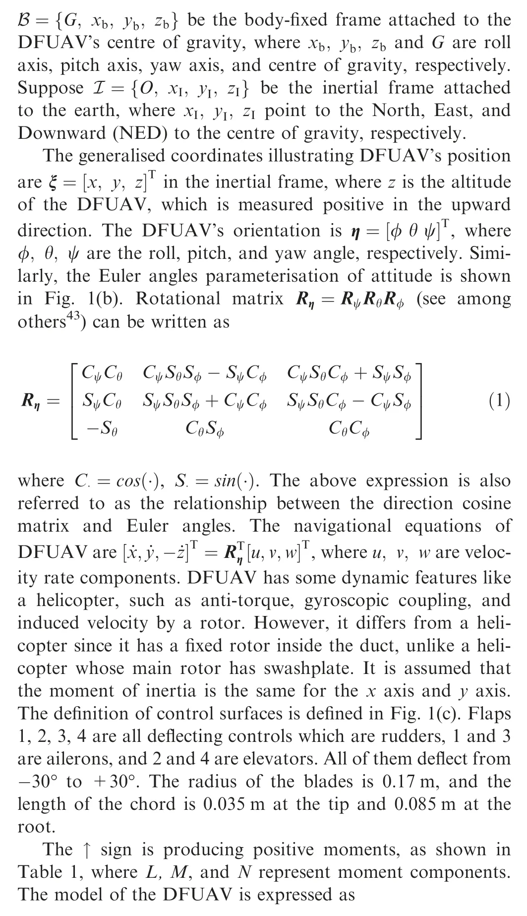
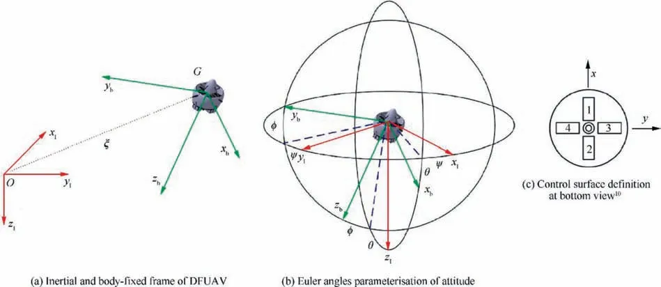
Fig. 1 DFUAV frames, Euler angles and control surfaces.

Table 1 Control surface sign conventions.10


Fig. 2 DFUAV flights, force and moment vectors.
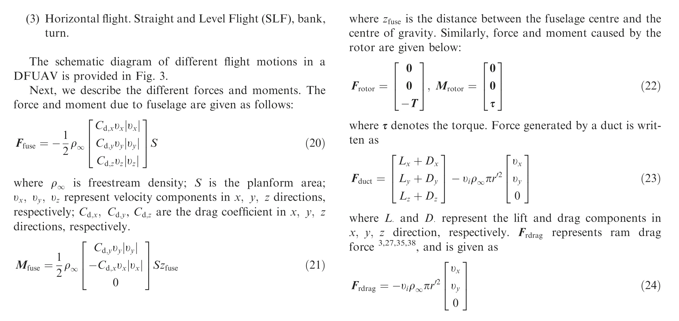

Fig. 3 DFUAV motion with various flight phases.
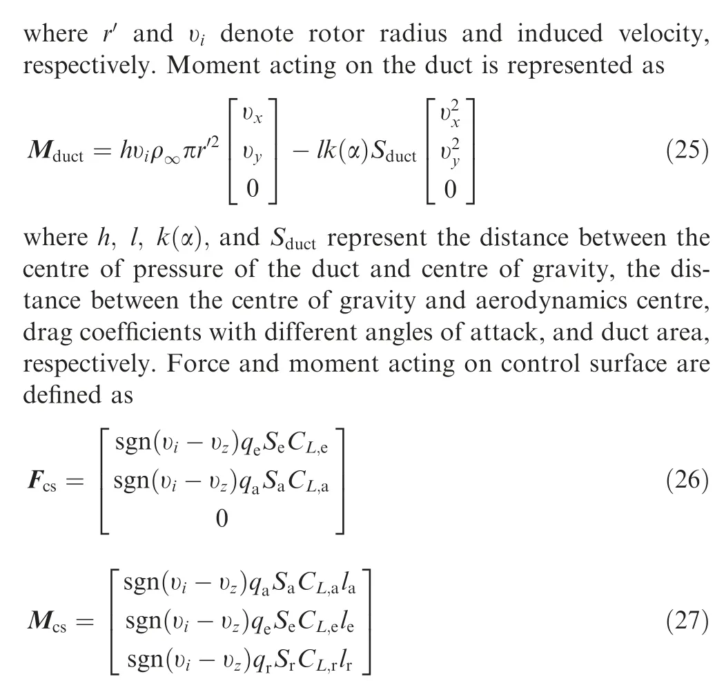
where CL,a, CL,e, CL,r, la, le, lrdenote the lift coefficient for aileron,elevator,and rudder and moment arm for aileron,elevator, and rudder, respectively; qa, qe, qrrepresent dynamics pressure for aileron, elevator, and rudder, respectively;Sa, Se,Srare the surface area of aileron,elevator,and rudder,respectively. The primary control principle in all the DFUAV is identical where control surfaces are inside fan slipstream,which gives forces and moments. Gravitational forces accounted on the DFUAV are as follows:

where b, ib, ωrare the number of blades, the moment of inertia of rotor blade, and rotor angular velocity, respectively.DFUAV possess rotational and translational motions concerning the centre of gravity. The brief method about the derivation of dynamics and parameters can be found in Ref.28
The DFUAV model is linearised through the Jacobian linearisation method according to different speeds at the desired flight operating envelope based on the gradient-based method using mathematical modelling.10The resultant values can be different from mathematical modelling and wind tunnel tests.However, discussing the effectiveness of one method to another is out of the scope of this article.
3. Control design and analysis
3.1. Control structure
To achieve the robust performance for both trajectory tracking and attitude control, two MPC controllers are designed: an outer loop for trajectory tracking, and an inner loop for attitude control. At first, the reference trajectories are provided to the outer loop for trajectory tracking and an attitude controller for the remaining states.An arbitrary desired trajectory for t ∈0,4π[ ], used to investigate the DFUAV control performance during flight modes, is given as

During FB motion,the north position of DFUAV executes a sinusoidal reference with an amplitude of 10 m,while the east position of the DFUAV remains at 0 with the UAV maintaining an altitude of 40 m throughout this motion. During LR direction, DFUAV remains at an altitude of 40 m, but the north and east position of the DFUAV maintain at zero and 10sint,respectively.The desired φ of the UAV in the LR direction remains at 0°.The basic principle of LSTF is the same as a helicopter in the forward flight, where parts of the thrust vector are leaning towards the direction of the motion.
The pirouette motion is required when the DFUAV has to alter its facing direction. It works exactly like the roll motion,except the pirouette is employed in the vertical attitude of the DFUAV. The DFUAV initially hovers at an altitude of 40 m with the belly facing north,and then a similar 10sint command is provided to the aileron controller to stabilise the φ angle.Moreover,both north and east positions of DFUAV maintain at zero.
For transition flight, another reference trajectory is generated.Like most tail-sitter aerial vehicles,45the transition flight in DFUAV consists of two parts: HtoL transition and LtoH transition.
For HtoL transition,17the desired trajectory can be given as

where vmax=15 m/s, vmin=0 m/s. In this transition framework, θ changes from 90° to 0°, while both φ and ψ angle maintain at 0°. Similarly, for LtoH transition17, the reference trajectory can be defined as

In this case, θ should change from 0° to 90°. The φ and ψ angle remain at 0°. The HtoL flight is difficult as compared to LtoH flight,because the vehicle is unstable at low-speed vertical flight before the motion, while the DFUAV has already attained a high-speed stable flight during LtoH flight. The transition manoeuvres can be performed by controlling both δeand δt.
Horizontal flight is a vital flight capability, where the DFUAV is configured to fly with high forward speed like in cruise flight mode. During this flight, the DFUAV maintains at a constant altitude (100 m)with the required forward speed of cruise mode.During this motion,the desired α and θ angles are 5°. During the high-speed forward flight or cruise mode,the DFUAV requires to accelerate vertically without the need to hover or to fly in low speed forward flight.
Since the pirouette motion is developed for any virtual direction of DFUAV, bank, and roll motion in the lateraldirectional flight is not required for the DFUAV to implement an autonomous mission.36Among these flight phases,only one of the control surfaces plays the part of dominant control. δtcontributes as a dominant control in ADH and SF. δaplays the dominant role in pirouette and bank.δeis necessary during LSTF, LtoH, HtoL, and climb. δris the primary controller during the turn.
DFUAV is subjected to different kinds of uncertainties and external disturbances. Moreover, the so-called ram drag force is considered in the internal model of the DFUAV due to the effect induced by the duct.Any disturbances and uncertainties are estimated and compensated with the help of a state observer using the Kalman Filter (KF). The brief procedure is shown in Fig. 4. A detailed discussion about control design is provided in the following section.
3.2. MPC design

Fig. 4 DFUAV control structure.
MPC is an advanced control strategy that uses the system model to predict the future behaviour of the system by solving an optimisation problem to get the control solution. Much of the development of MPC started in the process industry during the 1980s.46But, as the progress of time, due to its conceptual elegance and real-time application, it also began to deploy in other fields.In this paper,offset-free tracking MPC is designed for a linear system with constraints and state variables.A state observer based on KFs is used to estimate the continuous wind gust and other disturbances to stabilise the states. The linearised model can be derived from nonlinear Eqs.(3)-(8)using mathematical modelling through the Jacobian linearisation method.10The linear model is given as


Lemma 2.48Let the observer in Eq. (37) be stable. Select nd=p-, and the observer steady state satisfies

where Qx≥0, Ru≥0, RΔu≥0, and P represent penalties on state error, control input error, control change rate,and terminal state error penalty, respectively. In most cases,it is difficult to ensure stability and feasibility unless the adopted control strategy applied to the system is the Linear Quadratic Regulator (LQR). When the prediction horizon is N steps, stability and feasibility cannot be guaranteed. However, larger N can improve stability and feasibility issues, but it can also increase the computational load,so there is a tradeoff.The value of terminal cost and constraints must be chosen to ensure closed-loop stability and feasibility. By penalising control input Δu-kin Eq. (33), it is easier to avoid oscillations and ensure smooth control inputs.
An observer based on KF is designed, which can estimate the continuous wind gust and other disturbances and is given by

where ^x and ^d are the estimated state and estimated external disturbance, respectively. Lxand Ldare observer gains, and ym,kis the measured output, which can be measured at time k. Both Lxand Ldare selected so that the observer is stable.We assume that the results below are independent of the choice for evaluating the values of Lxand Ld.
Lemma 1.47Let the observer in Eq. (35) be stable. Then rank (Ld)=nd
Proof. From Eq. (35), the following form is given:


Remark 2.
It is noteworthy that, to get a zero offset, we augment the plant with an equal number of disturbances (& integrators)as we have measurements nd=p-. Also, the design requires the addition of p- integrators even if we want to control just a subset of r-<p-. The design steps for the case nd= r-<pare more involved.
Remark 3.
Extended Theorem 1 can be used to prove local Lyapunov stability of the closed-loop system (42).49
Next, we deal with the case where p-is greater than nd,because choosing nd=p- might increase the disturbance states and, in turn, makes the MPC problem more complicated.From the internal model principle, it is clear to have an additional disturbance state for each output to be tracked without offset. i.e. nd= r-<p- which does not guarantee offset-free tracking when the MPC problem is designed as Eq.(33),since Lemma 2 does not hold. To obtain an offset-free tracking, we present the procedure to construct an observer that can achieve offset-free tracking. The MPC problem in Eqs. (33),(41), and observer in Eq. (35) remain the same. However,Lemma 2 is replaced by the following lemma.
Lemma 3.47The observer steady-state satisfies


Fig.5 Translational and angular velocity components of applied continuous Dryden wind turbulence.


Fig. 6 Trajectory tracking of DFUAV for hover and cruise mode.
Once the MPC with a disturbance model is established, we can develop the system with input and state delays. As mentioned earlier, these delays are considered as uncertainties in the system along with other parametric uncertainties.
The system model with state and input delay is given as

where suand hsare the state and input delays,respectively.The prediction model can be formulated and the cost function in Eq. (34) can be utilised to compute the linear system in Eq.(50).
3.3. LQTI design


Fig. 7 3D trajectory tracking of DFUAV with disturbance and uncertainties (Hover mode).

Theorem 2. Suppose CLis any matrix such that QL=CTLCL.Let Aaand CLmatrices be observable, and then Aa,Baare controllable if and only if
(1) There is a unique positive definite solution S-(∞ ) to the Riccati equation.
(2) Closed-loop in Eq. (57) is asymptotically stable.

Table 2 Tracking error in presence of disturbances (MSE).


Table 3 Tracking error in presence of disturbances and uncertainties (MSE).
Then the observability requires xL→0.Hence the system(56)is asymptotically stable.
Riccati equation for the system (57) is given as


Fig. 8 Control inputs in hover, transition, and cruise mode.

Fig. 9 NED position and attitude tracking response during ADH flight.

3.4. Sufficiency

4. Simulation results
In this section, simulation results of DFUAV are provided to validate the performance of the given scheme.
4.1. System description
The simulations have been carried out with the help of Intel Core i5-5200 CPU(2.2 GHz)with 8 GB of RAM.The model parameters of the DFUAV used for simulations are provided as follows: m=4.8 kg, h=0.8 m, g=9.81 m/s2, Ixx=0.9 kg·m2,Iyy=0.9 kg·m2, Izz=0.14 kg·m2, ρ∞=1.2 kg·m-3, b=4,r′=0.17 m, S=0.061 m2, Cd,x=Cd,y=0.5, Cd,z=0.1,ib=0.0001 kg·m2, la=le=0.35 m, lr=0.13 m,Sa=Se=0.019 m2, Sr=0.023 m2, Sduct=0.1 m2, l=0.3 m,and k (α )=0.21 m. The initial conditions for the DFUAV’s position and attitude are ξ0= 0,0,0[ ]Tm and η0= 0,0, 0[ ]Trad, respectively. An uncertainty of 30% is considered in the mass,the moment of inertia,stability,and control derivatives.The continuous Dryden wind turbulence model for the translational and angular velocity components is given in Fig.5.

Fig. 10 NED position and attitude tracking response during FB and LR flight.
4.2. Controllers implementation


Finally, the linear model for transition mode is given as
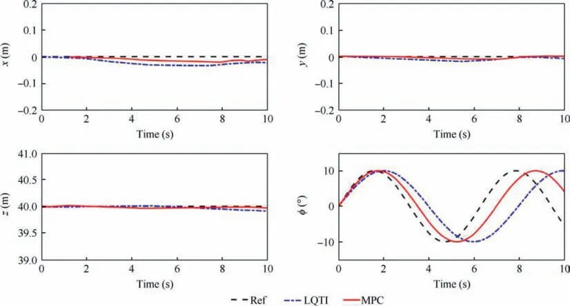
Fig. 11 NED position and attitude tracking response during pirouette flight.
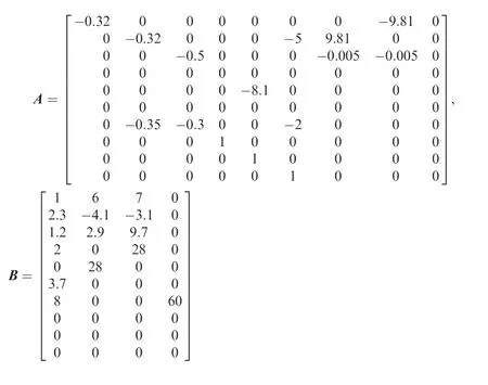
In hover and low-speed level flight,the vehicle longitudinal axis is vertical, or with a small angle of inclination. In transition flight mode,the vehicle tilts its body forward to accelerate,and in the high-speed level flight mode,the vehicle longitudinal axis is almost parallel to the horizon.51The controllability condition must be satisfied in all the flight modes.
Figs. 6(a) and (b) illustrate the 3D trajectory tracking of a DFUAV for hover and cruise mode,respectively.It is assumed that the initial position of the DFUAV is the same as the target trajectory, as shown in Fig. 6(c).
LQTI is preferred over LQT because of exhibiting low steady-state error capability. Unlike in Ref.10,a state observer with LQTI is also employed for estimating uncertainties and disturbances. However, to lower the computational time, a simple observer based on KF is adopted. Offset-free MPC achieves better disturbance rejection and constraint satisfaction,and provides adequate tracking performance.In the next subsections, we will discuss the tracking performance and robustness of various flight modes.

Fig. 12 Position and attitude tracking response during HtoL and LtoH flight.

Fig. 13 NED position and attitude tracking response during SLF flight.

Fig. 14 NED position in autonomous flight.
4.3. Flight modes

Fig. 15 NED position and attitude tracking response during autonomous flight.
The tracking performance of DFUAV in hovering mode is depicted in Figs. 6(a) and (c). To analyse the control performance, wind turbulence of over 1 m/s is applied to all the linear components at approximately 1 s. Consequently, the DFUAV still maintains its position (see Fig. 6(c)). It also validates previously held argument in Ref.35, which states that DFUAV in low-speed flight mode always has better tracking performance than the high-speed mode. DFUAV 3D trajectory for cruise mode is presented in Fig. 6(b). In this case,LQTI and offset-free MPC with their respective KFs do not have any considerable performance difference in terms of tracking performance. This is because, at high-speed manoeuvres, offset-free MPC with KF fails to adapt to the variations caused by the high-speed flight mode and almost behaves similarly like an LQTI with a significant difference as compared to the other modes like transition and hover.However,the simulation results confirm that the offset-free MPC ensures better control performance as compared to LQTI in cruise flight mode. A combination of both disturbances and uncertainties is applied to the DFUAV, as shown in Fig. 7.
The simulation results suggest that there is a significant tracking error due to the combination of uncertainties and disturbances, which are induced to the DFUAV system. Fig. 8 demonstrate the control input signals of hover, transition,and cruise flight modes.
MPC, along with KF, generates comparatively smoother control signals as compared to the LQTI. Detailed tracking error in the presence of disturbances and a combination of disturbances and uncertainties are provided in Tables 2 and 3,respectively. The derived simulation results conclusively indicate the disturbance rejection,constraint satisfaction,and efficient tracking performance of the designed methodology for the DFUAV.
4.4. ADHs
The position and tracking response of the ADH flight are shown in Fig. 9. During this flight, DFUAV needs to achieve certain altitudes as described before.The altitude plot also suggests that LQTI has a slightly slower response due to integral action.
4.5. LSTF flight
The tracking response for FB and LR flight are shown in Fig. 10, respectively. Due to the time delays introduced in the uncertainties,there is a phase delay during the simulations.However, the simulation results reveal that offset-free MPC conclusively performs better than LQTI.
4.6. Pirouette
The tracking response for the NED position and attitude of DFUAV in the presence of uncertainties and disturbances is shown in Fig. 11.
4.7. Transition flight
In this subsection, the trajectory tracking problem is further validated through transition flight. Simulation results have been executed based on two transition flight modes subject to a combination of external disturbances and different uncertainties. Fig. 12 show that offset-free MPC with KF achieves better tracking and steady-state performance with effective handling of disturbances and uncertainties as compared to LQTI and KF.
4.8. SLF flight
The tracking response during the SLF flight is depicted in Fig.13.The offset-free MPC has faster settling time and small tracking error as compared to LQTI.
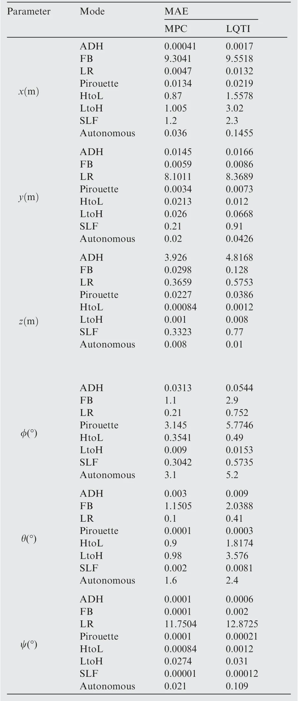
Table 4 Performance analysis in the presence of disturbances and uncertainties (MAE).
4.9. Autonomous flight
Finally, simulation results based on autonomous flight have been carried out to validate the performance of the designed controller. The flight characteristics of DFUAV are also crucial because they exhibit the properties of both fixed-wing UAV and helicopter UAV.41The flight mission starts from NED (0, 0, 0) m and ends at NED (0, -50, 0) m. The desired trajectories for the autonomous flight are given as follows:
Fig. 14 and Fig. 15 show the simulation results of flight motion of the whole DFUAV platform.Both of the controllers behave similarly in terms of tracking and steady-state performance. However, the LQTI has longer response time due to integral action, and it may underperform during the ADH motion as compared to MPC.
To make a quantitative comparison, a performance index based on Mean Absolute Error(MAE)is provided in Table 4,which demonstrates that offset-free MPC has better tracking performance as compared to LQTI.
5. Conclusions
In this article, an offset-free MPC framework has been developed to solve the trajectory tracking control of a DFUAV. The DFUAV model was subjected to continuous wind gust added to both translational and angular velocity components. Parametric uncertainties were added in mass,the moment of inertia, stability and control derivatives.Moreover, state and input delays are considered as uncertainty. The control strategy was divided into an outer and inner loop, and both stabilised through a combination of offset-free MPC and a KF. Numerical simulations were computed involving all flight modes of DFUAV. To show the effectiveness of the designed approach, a comparative analysis based on the LQTI technique was provided. The proposed strategy revealed better tracking, disturbance attenuation, and constraint satisfaction.
In the future, we are interested in developing MPC based composite flight control methodology involving advanced disturbance observers, which can compensate for disturbances and different types of uncertainties more efficiently.
Acknowledgements
This work was co-supported by the National Natural Science Foundation of China (Nos. 61225015, 61105092, 61422102,and 61703040),the Beijing Natural Science Foundation,China(No. 4161001), and the China Postdoctoral Science Foundation (No. 2017M620640).
 CHINESE JOURNAL OF AERONAUTICS2020年7期
- CHINESE JOURNAL OF AERONAUTICS的其它文章
- An experimental method for squealer tip flow field considering relative casing motion
- A novel none once per revolution blade tip timing based blade vibration parameters identification method
- Highly efficient computation method for hazard quantification of uncontained rotor failure
- Optimal motion cueing algorithm for accelerating phase of manned spacecraft in human centrifuge
- Effective control allocation using hierarchical multi-objective optimization for multi-phase flight
- Fault-tolerant control and vibration suppression of flexible spacecraft: An interconnected system approach
