Optimization on conventional and electric air-cycle refrigeration systems of aircraft: A short-cut method and analysis
Hongsheng JIANG, Sujun DONG, Hinn ZHANG, Fengming AI,Zhiwei ZHANG, Jun WANG
a School of Aeronautic Science and Engineering, Beihang University, Beijing 100083, China
b Key Laboratory of Cryogenics, Technical Institute of Physics and Chemistry, Chinese Academy of Sciences, Beijing 100190, China
c Shenyang Aircraft Design and Research Institute, Shenyang 110013, China
KEYWORDS Aircraft;Air-cycle refrigeration;Electric air-cycle refrigeration;Parameter matching;Sensitivity analysis
Abstract The air-cycle refrigeration system is widely used in commercial and military aircraft,and its efficiency greatly affects aircraft performance. Nowadays, this system requires a more efficient design and optimization method.In this paper,a short-cut optimization method with high efficiency and effectiveness is introduced for both conventional and electric air-cycle refrigeration systems.Based on the system characteristics, a four-layer parameter matching algorithm is designed which avoids computational difficulty caused by simultaneous equations. Fuel penalty is chosen as the objective function of optimization; design variables are reduced based on sensitivity analysis to improve optimization efficiency. The results show that the 3-variable optimization of the conventional air-cycle refrigeration system can obtain almost the same results as the traditional 6-variable optimization in that these two optimizations can both significantly reduce the fuel penalty.However,the computer running time of the 3-variable optimization is much shorter than that of the 6-variable optimization. The optimal fuel penalty of the electric air-cycle refrigeration system is lower than that of the conventional one. This study can provide reference for optimizing the aircycle refrigeration system of aircraft.
1. Introduction
Over the past decades, there has been tremendous progress in the efforts to move toward a More Electric Aircraft(MEA).1,2Compared with conventional aircraft, the MEA uses electric power to fully or partially replace secondary power such as hydraulic, mechanical and pneumatic power, eliminating central hydraulic pumps, gearboxes, bleed-air components, and other accessories.3-6It simplifies the structure of aircraft and engines, and improves efficiency of energy utilization. Thus,the costs for manufacture and maintenance can be greatly reduced. Among secondary power subsystems, an Air-Cycle Refrigeration System of Aircraft (ACRSA) is the core of the environmental control system,7-9consuming a large amount of secondary power.10In the studies of an ACRSA, there are two new demands for optimization design and faster optimization.
First, the efficiency of an ACRSA greatly affects aircraft fuel consumption and flight distance11; therefore, design and optimization of an ACRSA has become an important demand,attracting increasing research attention.Liu et al.12analyzed a simple ACRSA,and found an optimal pressure ratio providing maximum energy efficiency. Bender13integrated an exergy method with a model of an ACRSA and simulated exergy efficiency at different phases of a flight mission. Islam and Dincer14analyzed a system integrating air-cycle refrigeration and power generation,investigating the effects of three parameters on the system performance. Based on minimum weight and minimum entropy generation, Pe´rez-Grande and Leo15optimized two finned cross-flow heat exchangers used in an ACRSA as well as the whole system. The dimensions of the two heat exchangers were obtained with a highly satisfactory trade-off solution. Ordonez and Bejan16proposed four types of models, including simple and complex ones, to optimize the environmental control system of aircraft. The results showed that the optimized air delivery temperature was insensitive to the size of the heat exchangers used in the bootstrap air cycle. These representative studies have promoted the development of ACRSA optimization methods.
However,such studies remain narrow in focus,dealing only with the Conventional ACRSA(C-ACRSA).The development of the MEA requires more in-depth investigations into assessment and optimization of an Electric ACRSA (E-ACRSA).Therefore, a comparison between an E-ACRSA and CACRSA is necessary,and the optimization method and performance of an E-ACRSA are worthy of further studies.
Another demand in the research area of an ACRSA is faster optimization. With the development of aircraft thermal management, an integrated environmental control system has been proposed17composing of an ACRSA, the vapor compression refrigeration system, the liquid cooling system, and the fuel thermal management system. The integrated system becomes more and more complex,and its optimization usually aims at fuel penalty along with flight profile of the whole aircraft, causing a huge amount of calculation. Quick and effective calculation of the ACRSA is necessary for optimizing the whole system. Therefore, it is important to improve computational efficiency of ACRSA optimization.
In this study,a short-cut optimization method is proposed,and optimization is performed for both a C-ACRSA and an EACRSA for a 150-seat passenger aircraft.Based on the system characteristics, a four-layer parameter matching algorithm is designed. Fuel penalty is chosen as the objective function.Based on sensitivity analysis, design variable reduction is achieved to improve computational efficiency. The CACRSA and E-ACRSA are then compared, showing that the optimization method of this paper can significantly improve the effectiveness and efficiency of optimization. This study can provide valuable insight into the new demands of aircraft environmental control.
2. System description
The schematic diagrams of a typical C-ACRSA with a threewheel bootstrap and of an E-ACRSA are shown in Fig. 1 and Fig.2,respectively.It can be seen that these two diagrams are almost identical, except for system inlets. The C-ACRSA uses bleed air as the system inlet, while the E-ACRSA uses an electric compressor to offer high pressure. For these two systems, high pressure air flows through heat exchangers and compressors, and flows into turbines and the cold side of condensers in turn, and finally reaches cabins. It can be seen that the cold side of condensers is the air from turbine outlets,and that the hot side is humid air about to flow into turbines. The hot-side air is cooled by the cold-side air.The water separated by water extractors is transported to ram air inlets and mixed with ram air to reduce inlet temperature of secondary heat exchangers (HX2) and to improve its heat transfer efficiency.
The E-ACRSA utilizes electric power instead of pneumatic power;therefore,motors,controllers and other electric components are added, and pneumatic components are reduced due to the absence of engine bleed air.In addition,it is convenient for the E-ACRSA to share electrical energy with other systems in an aircraft.
3. Modeling and optimization method
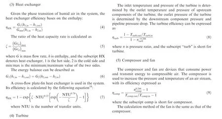
3.1. Calculation of component characteristics
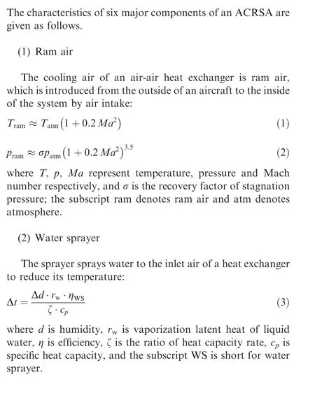
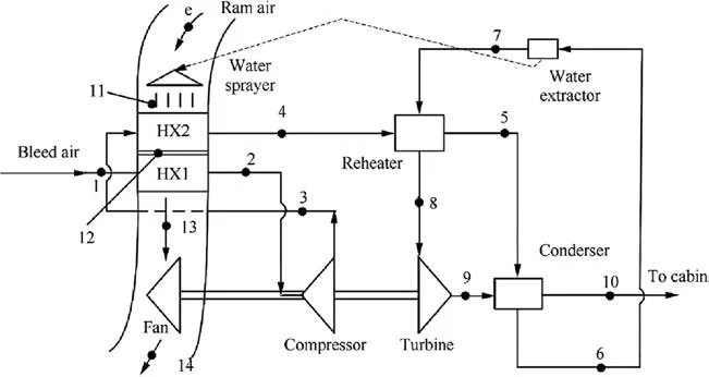
Fig. 1 Scheme of typical C-ACRSA.
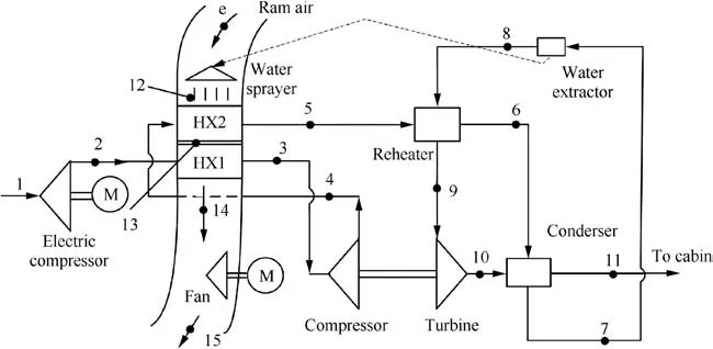
Fig. 2 Scheme of typical E-ACRSA.
3.2. Optimization objective function
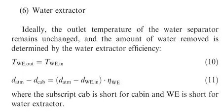
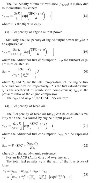
As an ACRSA consumes energy from fuel, its performance can be evaluated by fuel penalty, and thus fuel penalty is chosen in this study as the objective function. This function has four origins: system device mass, ram air resistance, engine output power and engine bleed air.
(1) Fuel penalty of system device mass
The mass of a cross-flow plate-fin heat exchanger (mHX) is calculated as19
3.3. Parameter matching algorithm
To calculate the objective function, the state parameters of nodes and performance parameters of the components should be known. Therefore, it is necessary to solve these parameters from the design variables based on the system and component characteristic equations under a certain flight condition and with design specifications.This process is called system parameter matching, an important calculation in optimization. In simple thermodynamic systems, this calculation can be conducted through simultaneous equations.However,an ACRSA is a much more complex system and its parameter matching calculation is difficult to be achieved directly by solving all characteristic equations.21,22A special parameter matching algorithm needs to be designed.
3.3.1. Input parameters
Before parameter matching calculation,it is necessary to determine the known parameters as input conditions of the algorithm. There are three types of input parameters: flight conditions, engine and aircraft performance, and design specifications.
The parameters of flight conditions are flight height, Mach number, moisture content of ram air, etc. For the C-ACRSA,temperature, pressure and moisture content of bleed air are also included.
The parameters of engine and aircraft performance mainly include the thrust-specific fuel consumption, pressure ratio of the engine compressor,inlet temperature of the engine turbine and compressor, fuel calorific value, coefficient of combustion completeness, and aerodynamic resistance of the aircraft.
Design specifications include the flow rate, temperature,pressure, and moisture content of supply air to the cabin,because an ACRSA aims at meeting the requirement of the crew’s need for fresh air, removing heat load and moisture load, and maintaining cabin pressure.
3.3.2. Parameter matching
Parameter matching is the key step for system design.The task of parameter matching calculation is to determine a system design scheme, that is, to reasonably determine the state parameters of every point in the system in order to satisfy the requirements for system performance. The performance parameters of each component can also be defined, for example, the efficiency and ratio of the heat capacity rate of heat exchangers, the pressure ratio and efficiency of (electric) compressors and turbines, the water separate efficiency of the whole water separate subsystem.Further,the results of parameter matching can be used as the design specification of each component.
The process of parameter matching contains iterations for the performance of the turbine and compressor module, and iterations for the humid air state parameters of each point.Therefore, the parameter matching algorithm is divided into four levels: parameter, component, module and system. The basic algorithm is shown in Fig. 3.
In the system level,the total mass is calculated based on the system configuration and the parameters of each state point.Then,thefuelpenaltyisobtainedthroughtheengineperformance and flight conditions based on the equations in Section 3.2.
In the module level, the compressor-turbine module is calculated, which includes the turbine, compressor and heat exchanger. The function of this module is relatively independent, and the characteristic equations of the compressor and turbine include couple relationships between temperature and pressure, which need repeated iterations. Therefore, this module is calculated separately.
In the component level, the inlet and outlet air parameters are calculated based on the characteristic equations of the components shown in Section 3.1. The results of the components inside the compressor-turbine module are sent to the module level, and those outside the compressor-turbine module are directly sent to the system level.
The parameter level is mainly used to calculate the state parameters of humid air. Most of the thermophysical properties can be calculated directly without iterations except in some conditions when phase change exists in moist air.In these conditions, temperature, partial pressure of saturated vapor, and saturated moisture content need to be solved by simultaneous equations.
Fig. 4 shows the flow chart of parameter matching process which considers the characteristics of the C-ACRSA.In Fig.4,the corresponding position of each state point number is presented in Fig. 1.
As shown in Fig.4,the 1st-3rd steps determine the parameters of bleed air, system outlet and ram air. The 4th step involves the iteration to solve the module containing the compressor, intermediate heat exchangers and turbine. The 5th step calculates the parameter of the fan, and the 6th step the fuel penalty of the system.
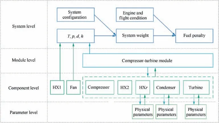
Fig. 3 Diagram of parameter matching levels of ACRSA.
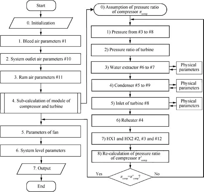
Fig. 4 Flow chart of parameter matching of C-ACRSA.
The iteration process, Step 4, in the compressor-turbine module is described in detail as follows, and the other steps can be directly calculated using the equations in Section 3.1.
(1) Set the pressure ratio of the compressor, πcomp.
(2) Calculate the pressures of each component from Point 3 to Point 8 at a certain flow rate based on the resistance coefficients.
(3) Calculate the pressure ratio of the turbine, πturb.
(4) Calculate the state before and after the water extractor(Points 6 and 7):The moisture content is obtained based on Eq. (11). Then, the iteration of physical properties is conducted to obtain specific enthalpy h6,partial pressure of saturated vapor p6s, temperature T6, and finally h7based on the moisture content and pressure of Point 7,which is at a saturated state.
(5) Choose the efficiency of the condenser,ηcond,and calculate the inlet parameters of the condenser (Points 5 and 9) by combining Eq. (4) and Eq. (5):

(6) Choose the efficiency of the turbine, ηturb, and calculate the turbine inlet temperature (Point 8) according to Eq.(8).
(7) Calculate the inlet parameters of the reheater hot side(Point 4) based on Eq. (6).
(8) Choose the efficiency of the primary heat exchanger,ηHX1, and the ratio of heat capacity rate, ζ. Calculate T2, T3, and T12by solving the following simultaneous equations which are Eq. (4), Eq. (5) and Eq. (9):

(9) Choose the efficiency of the compressor, ηcomp, and the ratio of fan power to turbine power, β. Recalculate the compressor pressure ratio according to the power balance of the turbine, compressor and fan:

Based on the process described above, we choose six variables to be the principal design variables, which are the condenser efficiency ηcond, turbine efficiency ηturb, the efficiency of the primary heat exchanger, ηHX1, the heat capacity rate ratio ζ, the compressor efficiency ηcomp, and the ratio of fan power to turbine power, β. The reheater efficiency, ηHXr, can then be calculated by solving simultaneous equations of the heat exchanger efficiency and energy balance when input and output temperatures are known. The same approach can be applied to calculate the efficiency of the secondary heat exchanger, ηHX2; the calculation of the pressure drop on each component is simplified with the resistance coefficient. Therefore, the six variables (ζ, ηHX1, ηcomp, ηturb, ηcondand β) are used as the optimization variables.
It can be seen from Fig. 2 that the E-ACRSA differs from the C-ACRSA in two aspects. First, the electric compressor replaces bleed air; second, ram air is driven by the electric fan, so the whole output work of the turbine can be used to drive the compressor. Thus, all of the components and procedures except the electric compressor are identical for both the C-ACRSA and the E-ACRSA. The parameter matching algorithm can also be the same except that for the ratio of fan power to turbine power, β, should be set to zero, and that the fan parameters should be calculated separately using ram air parameters.
The electric compressor requires two new parameters: the electric compressor efficiency, ηecom, and the pressure ratio of the electric compressor, πecom. ηecomcan be set as a constant according to design, and πecomshould be introduced as an additional variable in order to obtain the output temperature and pressure of air flow out of the electric compressor. Therefore, the parameter matching algorithm should include a step of calculating outlet parameters of the electric compressor.The flow chart of the parameter matching process for the E-ACRSA are shown in Fig. 5.
3.3.3. Verification
To verify the correctness of the parameter matching algorithm,Engineering Equation Solver (EES), a general equationsolving program, is used to solve the sets of characteristic equations for comparison under same conditions, which are listed in Table 1.
The pressure-enthalpy diagram of the results is shown in Fig. 6. We can see that, the results calculated using fourlayer parameter matching algorithm are almost coincide with those from EES,which means the proposed method is suitable for calculating the parameters of both C-ACRSA and EACRSA. Moreover, four-layer parameter matching algorithm does not need very accurate initial value.However,when using EES to solve the equations,we should set the initial value and boundary carefully or it will be stuck in the process of calculation.
4. Sensitivity analysis and optimization
4.1. Design conditions
We conduct calculations of design and optimization based on a 150-passenger commercial aircraft on a hot day. The flight conditions, engine parameters and design specifications of the aircraft are shown in Table 2.
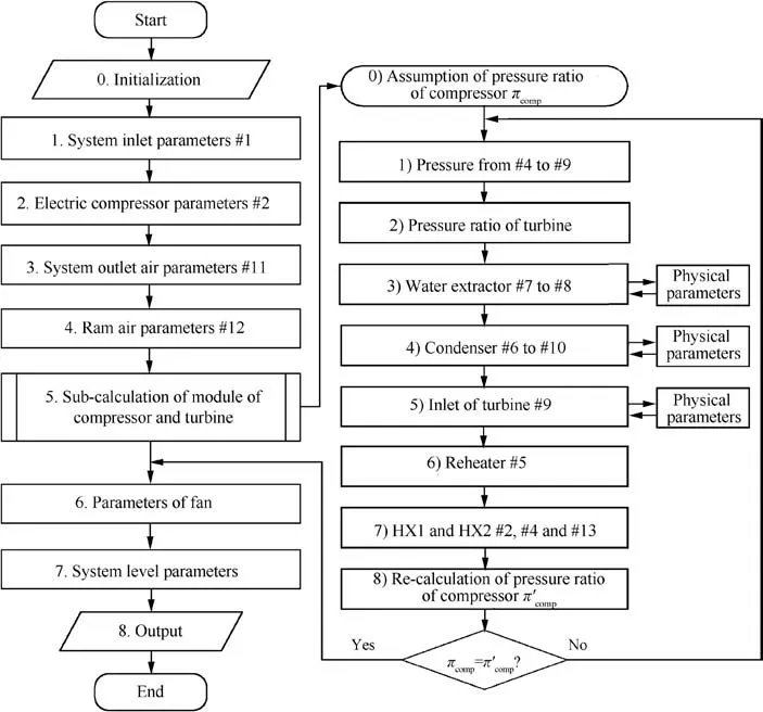
Fig. 5 Flow chart of parameter matching of E-ACRSA.
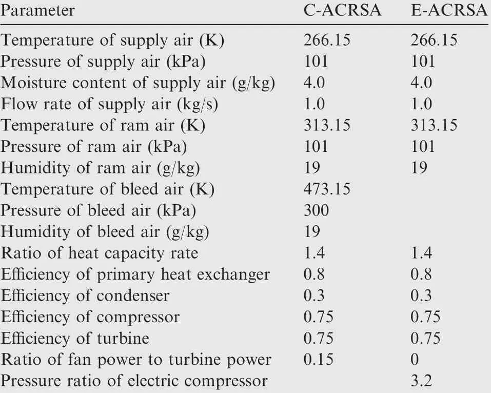
Table 1 Calculation conditions for verification.
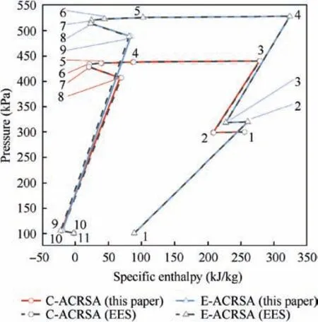
Fig. 6 Pressure-enthalpy diagrams of verification results.
As mentioned in Section 3.3.2,there are six variables for the C-ACRSA. The pressure ratio of the electric compressor is added for the E-ACRSA, while the ratio of fan power to turbine power is removed,set to zero.Therefore,there are also six variables for the E-ACRSA. According to the current design and manufacture of components,the maximum and minimum values of each design variable as the interval limits for optimization are chosen, as shown in Table 3. The parameters of the three-wheel bootstrap ACRSA from Ref.23 are also listed in Table 3 as a baseline for comparison.
4.2. Sensitivity analysis
An ACRSA has many design variables, so the parameter matching algorithm involves complex repeated iterative processes. Moreover, the efficiency of a compressor and turbine have a highly nonlinear coupling relationship and their ranges are relatively narrow; therefore, computational costs are huge if direct optimization is applied for design variables. Thus, a sensitivity analysis of the six variables of the C-ACRSA is performed based on fuel penalty.
In order to ensure randomness and uniformity of the initial point of the samples,we sample the data using the Latin hypercube sampling method.23This method is a multi-dimensionalhierarchical random sampling method,providing good uniformity and representativeness for data sets.For the six variables(six dimensions) of the C-ACRSA, the respective value intervals are evenly divided into 1400 non-overlapping cells. Every time we sample,a cell is extracted from each dimension,and a point is randomly selected inside the cell as its representative.Then, the selected representatives are grouped into a vector.Once a cell is selected, it will not be sampled again for its dimension.The sampling process is shown in Fig.7.This process is repeated until all the 1400 cells are sampled;that is,the 1400 sets of data are generated.
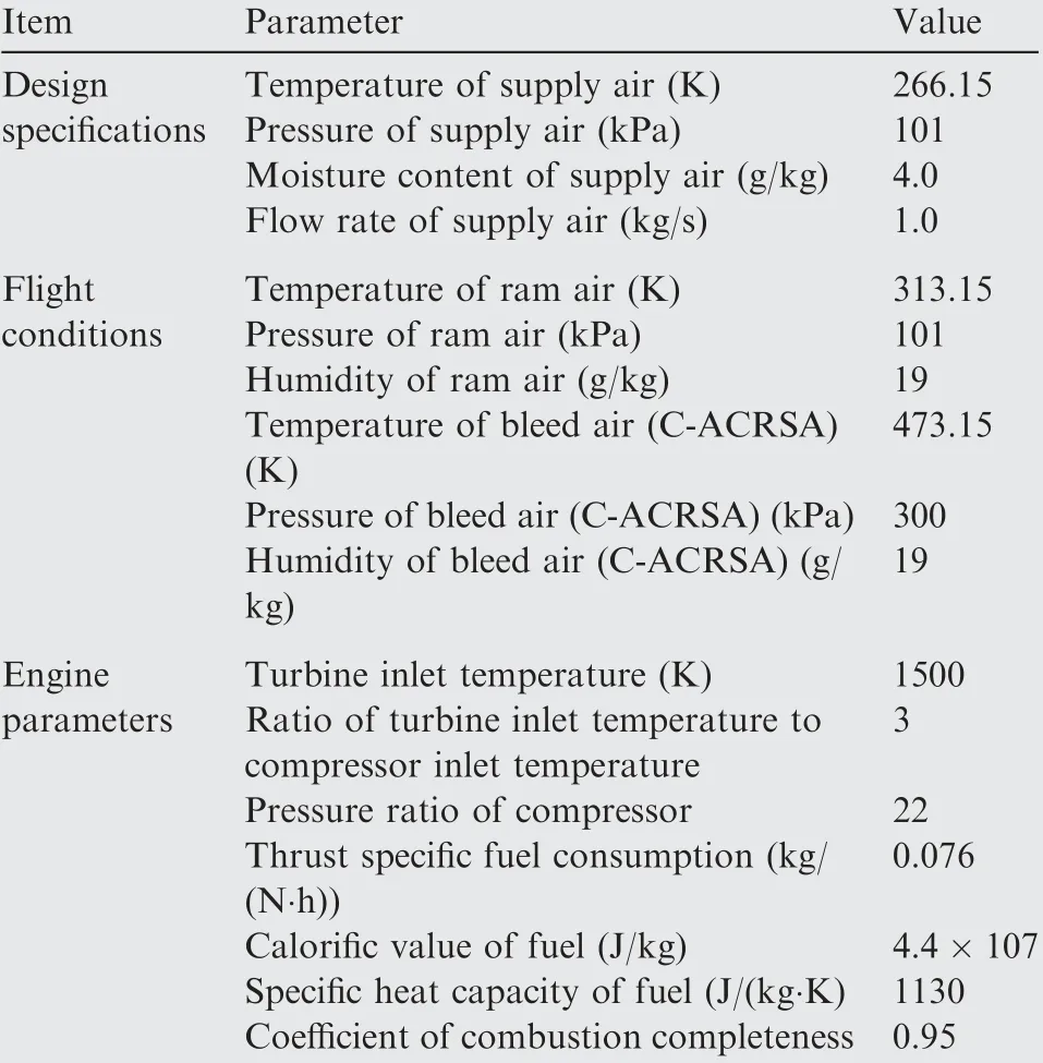
Table 2 Design conditions.
With the 1400 data sets as the values of design variables,the parameter matching program of the C-ACRSA is used to obtain the fuel penalty; the scatter plots using individual design variables as the abscissa are shown in Fig. 8.
In each subplot, the vertical distribution of the points shows the possible fuel penalty values when the corresponding variable of this subplot is fixed at a certain value and other variables vary. At a certain abscissa, the influence on the fuel penalty is higher when the point distribution is denser. The lower envelope line of all the points in the subplot shows the smallest possible fuel penalty with the corresponding variable of this subplot.
As can be seen from Fig.8,in each subplot,the fuel penalty values show a denser distribution at the bottom area. In addition, the minimum fuel penalty does not change substantially with the ratio of fan power to turbine power, though it decreases roughly linearly with the efficiency of the compressor and turbine.Thus,the ratio of fan power to turbine power can be set according to the actual need, and the efficiency of the turbine and compressor should be set as large as possible for the current levels of design and manufacture.
Therefore, the optimization of the C-ACRSA mainly focuses on three design variables, which are the ratio of the heat capacity rate, efficiency of the primary heat exchanger,and condenser efficiency. The pressure ratio of the electric compressor should be added for the E-ACRSA, resulting in a total of four design variables.

Table 3 Original values and ranges of design variables.
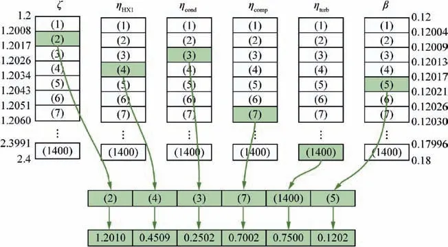
Fig. 7 One step of Latin hypercube sampling process.
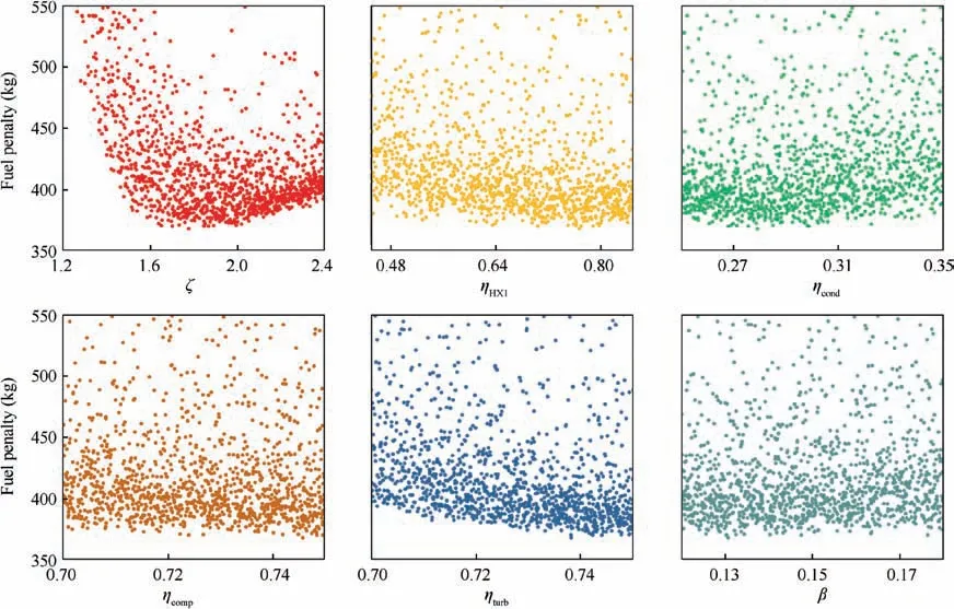
Fig. 8 Scatter plots of fuel penalty varied with design variables of C-ACRSA.
4.3. Results and discussion of optimization
4.3.1. Optimization algorithm
The problem of optimizing ACRSA is solved by the interiorpoint method, a penalty method.24This method constructs a penalty function according to constraints:the points in the feasible region are not punished,and the points farther away from the feasible region are punished. Using the penalty function,the original constraint problem is transformed into a series of unconstrained optimization problems, so that the search for the optimal value does not exceed the feasible region.For the optimization algorithm in this paper, the search step size and relative precision are limited to 10-3. The midpoints of the optimization variable ranges are chosen as the initial values.As the system shows the characteristics of convex optimization, the initial values have little effect on computational efficiency and optimization.
4.3.2. Comparison of different numbers of variables
The algorithm proposed is first used to solve the optimization problems of the C-ACRSA with six variables (ζ, ηHX1, ηcond,ηcomp,ηturband β)and with three variables(ζ,ηHX1and ηcond).The results of these two problems are presented in Table 4,and they are referred to as 6-variable and 3-variable for short.For the 3-variable optimization, we set the efficiency of the compressor and turbine to be 0.75, which is the maximum value of the interval, and set the fan power ratio to be 0.15, which is the midpoint of the interval.
It can be seen from Table 4 that the target functions (fuel penalty) of the 3-variable and 6-variable optimizations differ only by 0.33%,and optimization results of the other variables are rather close except for the fan power ratio β.The 6-variable optimization of the efficiency of the compressor and turbine is the upper limit of the interval, as predicted in the sensitivity analysis. Thus, the correctness of the sensitivity analysis and of the 3-variable optimization method is verified. Moreover,it can be inferred that further improvement of the design and manufacturing of compressors and turbines and increase of the upper limit of efficiency will play a decisive role in reducing fuel penalty.
Table 5 shows the time consumed running 3-variable and 6-variable optimizations on the same computer (configuration:Intel Xeon CPU E3-1230 V5 3.40 GHz, 8 GB RAM andWindows 10 platform with MATLAB 2018b). It can be seen that the 3-variable optimization method takes 44.33% less time than the 6-variable method.
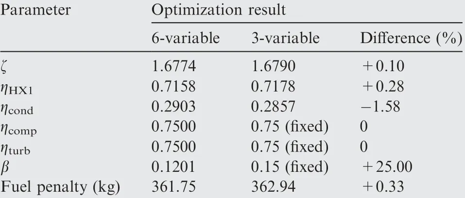
Table 4 Optimization results of C-ACRSA.
In summary, the 3-variable optimization method extracts the key design variables and simplifies the optimization process through sensitivity analysis, which can significantly accelerate ACRSA optimization while ensuring its accuracy.
4.3.3. Optimization of E-ACRSA and comparison between CACRSA and E-ACRSA
Based on the three variables(heat capacity rate ratio, primary heat exchanger efficiency, and condenser efficiency) for the CACRSA, the E-ACRSA adds the pressure ratio of the electric compressor as the design variable, and sets the ratio of fan power to turbine power to zero. It is assumed that the design specification, flight condition and engine parameters of the EACRSA are the same as those of the C-ACRSA.The interiorpoint method is used to perform the optimization calculation,and the results are listed in Table 6,along with the baseline system in Ref.23 and 3-variable C-ACRSA optimization results.The pressure-enthalpy diagram of these three systems are shown in Fig.9.
It can be seen from Table 6 that the fuel penalty of the optimized C-ACRSA is reduced by 24.2 kg (about 6.25%) compared with that of the baseline system, suggesting that the optimization effect is remarkable. Fig. 9 shows that the outlet pressure of the compressor and the inlet pressure of the turbine of the optimized C-ACRSA are increased compared with those of the baseline system. That is, the pressure ratio of the compressor and turbine is higher and the temperature drop in the turbine increases. This also shows that the increment of the pressure ratio of the turbine plays an important role in reducing the fuel penalty of the system. The fundamental reason for these results is that the ACRSA gradually cools the bleed air to supply for the cabin through the turbinecompressor module and heat exchangers. When the temperature drop of the system is constant,the demand for the temperature drop of heat exchangers can be reduced if the temperature drop of the turbine increases.Obviously,to generate the same amount of the temperature drop,the fuel penalty of increasing the pressure ratio of the turbine is lower than that of increasing the heat exchanger efficiency, which leads to a better system scheme.
Furthermore,Table 6 shows that although the E-ACRSA is heavier than the C-ACRSA, its fuel penalty is reduced by 35.79 kg(about 9.24%)compared with that of the baseline system and by 11.6 kg (about 3.19%) compared with that of the optimized C-ACRSA. This shows that the energy efficiency of the E-ACRSA itself is significantly improved. The reason for this result can be seen from Fig. 9. Compared with the C-ACRSA, the E-ACRSA has a lower highest pressure, and its outlet pressure of the electric compressor is also lower thanthe bleed air. This is mainly due to the fact that the inlet temperature and pressure of the E-ACRSA are not constant when an electric compressor replaces bleed air, and increase as the pressure ratio of the electric compressor increases.The electric compressor can provide higher outlet pressure when its pressure ratio increases,which is desirable for the system,but consumes extra electric power and leads to larger fuel penalty,which may counteract the benefit from higher pressure.Therefore, the optimization result is a trade-off of various factors:the pressure ratio of the electric compressor is 2.661; that is,the pressure of outlet air is 268.761 kPa, which is less than the bleed air pressure of the C-ACRSA, 300 kPa. Meanwhile,the ratio of the heat capacity rate of the E-ACRSA is higher,and the efficiency of the primary heat exchanger is lower. In summary, the E-ACRSA shows higher energy efficiency and lower fuel penalty than the C-ACRSA.

Table 5 Running time of optimization.

Table 6 Comparison of optimization results.
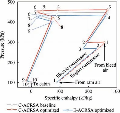
Fig. 9 Pressure-enthalpy diagrams of C-ACRSA and EACRSA.
5. Conclusions
This paper introduces a short-cut optimization method for the Air-Cycle Refrigeration System of Aircraft(ACRSA),and the optimization of a Conventional ACRSA (C-ACRSA) and an Electric ACRSA (E-ACRSA). The main findings are listed as follows.
(1) Considering the system characteristics, we design a parameter matching algorithm with four-layer structure.The four layers include parameter, component, module and system layers.The algorithm can satisfy the characteristic equation of each component,and avoid the computational difficulty caused by simultaneous equations.
(2) On the basic structure of the parameter matching algorithm, calculations for the C-ACRSA and E-ACRSA are conducted,and the key design variables for both systems are obtained through sensitivity analysis. For the C-ACRSA, the design variables include the ratio of the heat capacity rate, efficiency of the primary heat exchanger, efficiency of the condenser, efficiency of the compressor, efficiency of the turbine, and ratio of fan power to turbine power. For the E-ACRSA, the pressure ratio of the electric compressor is included based on the variables of the C-ACRSA, and the ratio of fan power to turbine power is set to zero.
(3) Fuel penalty is chosen as the objective function of optimization, and a sensitivity analysis for the design variables of the C-ACRSA is performed. Results show that ratio of the heat capacity rate, efficiency of the primary heat exchanger, and efficiency of the condenser can be selected as the design variables, while the efficiency of the compressor and turbine should be set to the upper limit of the range, and the ratio of fan power to turbine power has little influence on the objective function. The optimization results of the three variables are close to those of the six variables. For the EACRSA,the design variables can be reduced to the three variables of the C-ACRSA along with the pressure ratio of the electric compressor.
(4) Compared with the baseline system, the fuel penalty of the optimized C-ACRSA is greatly reduced, showing a remarkable optimization effect. The optimized system also has a higher pressure ratio of compressor and pressure ratio of turbine. Compared with the optimized CACRSA,the optimized E-ACRSA has smaller fuel penalty though it is heavier, showing that the energy efficiency is significantly improved. In addition, the outlet pressure of the electric compressor of the E-ACRSA is lower than the bleed air pressure of the C-ACRSA,which is a trade-off result of various factors.
(5) This study examines the typical types of an ACRSA;however, the optimization method proposed in this paper can be used for other ACRSA with similar components and processes.
Acknowledgements
The authors gratefully acknowledge the financial supports from Pre-research Project of National Defense Foundation and National Natural Science Foundation of China (No.51706232).
 CHINESE JOURNAL OF AERONAUTICS2020年7期
- CHINESE JOURNAL OF AERONAUTICS的其它文章
- An experimental method for squealer tip flow field considering relative casing motion
- A novel none once per revolution blade tip timing based blade vibration parameters identification method
- Highly efficient computation method for hazard quantification of uncontained rotor failure
- Optimal motion cueing algorithm for accelerating phase of manned spacecraft in human centrifuge
- Effective control allocation using hierarchical multi-objective optimization for multi-phase flight
- Fault-tolerant control and vibration suppression of flexible spacecraft: An interconnected system approach
