A novel control method for turboshaft engine with variable rotor speed based on the Ngdot estimator through LQG/LTR and rotor predicted torque feedforward
Yong WANG, Qin’gng ZHENG, Zhigui XU, Hio ZHANG,*
a College of Energy and Power Engineering, Nanjing University of Aeronautics and Astronautics, Nanjing 210016, China
b AECC Aero Engine Control System Institute, Wuxi 214063, China
KEYWORDS LQG/LTR;Ngdot estimator;Rotor predicted torque feedforward;Turboshaft engine;Variable rotor speed
Abstract In order to compensate for the disturbance of wide variation in rotor demanded torque on power turbine speed and realize the fast response control of turboshaft engine during variable rotor speed,a cascade PID control method based on the acceleration estimator of gas turbine speed(Ngdot) and rotor predicted torque feedforward is proposed. Firstly, a two-speed Dual Clutch Transmission (DCT) model is applied in the integrated rotor/turboshaft engine system to achieve variable rotor speed. Then, an online estimation method of Ngdot based on the Linear Quadratic Gaussian with Loop Transfer Recovery (LQG/LTR) is proposed for power turbine speed cascade control. Finally, according to the cascade PID controller based on Ngdot estimator, a rotor demanded torque predicted method based on the Min-batch Gradient Descent-Neural Network(MGD-NN) is put forward to compromise the influence of rotor torque interference. The simulation results show that compared with cascade PID controller based on Ngdot estimator and the one combined with collective pitch feedforward control,the novel control method proposed can reduce the overshoot of power turbine speed by more than 20%,which possesses faster response,superior dynamic effect and satisfactory robustness performance. The control method proposed can realize the fast response control of turboshaft engine with variable rotor speed better.
1. Introduction
In 2017,a new type of tiltrotor V-280 attracted the worldwide attention once more.The successful flight-test of V-280 breaks through the speed limit of the convention rotorcraft once again. It is probably that V-280 will replace the Black Hawk in service and becomes one of the most widely used rotorcrafts in the U.S.Army.Such significant profits are attributed to the application of variable rotor speed technology.1
It is predictable that variable rotor speed tends to be one of the core technologies for the sustainable development in rotorcraft.However,variable rotor speed creates an inevitable control problem to be solved urgently as well. The wide variation of rotor speed enhances the coupling dynamics between the helicopter subsystem and the engine subsystem, and causes remarkable uncertainty in the working point and surge margin of the turboshaft engine,2which presents a great challenge to the design of high-quality and fast response control methods for turboshaft engine.
Currently, NASA intends to adopt two schemes to realize variable rotor speed.3,4One is to design appropriate transmissions with variable gear ratio,and the other is to adjust power turbine speed to realize variable rotor speed. Both methods have their advantages and disadvantages unavoidably. However, no matter which scheme is applicable, the more complicated aerodynamic/structural mechanics/engine coupling dynamic control problem needs to be properly addressed.5,6
How to realize the rapid response control of turboshaft engine more superiorly is one of the emphases and difficulties in helicopter field. Nowadays, the cascade PID control structure combined with collective pitch feedforward is widely available in constant speed control of turboshaft engine,7-9which compensates the interference of main rotor load on turboshaft engine through collective pitch. Cai et al.10developed a control structure for gas turbine engine, which consists of a controller,an engine estimator and a load estimator.The load estimator can evaluate power turbine speed, torque and rotor load according to the input signals, and transmits them to the controller to achieve closed-loop control. HPW3000 engine controller predicts the transient variation of rotor torque through neural network that is accessible as the feedforward compensation loop of turboshaft engine. Meanwhile, it possesses the operation control mode from idle speed to high speed with guide vanes in advance, which further improves the accelerated response ability in acceleration process.11Based on the linear helicopter/engine model, Jaw and Mattingly12adopts LQG/LTR control method to reduce the overshoot of power turbine speed significantly. The response bandwidth is doubled compared with the Linear Quadratic Regulator (LQR) control method. Yan13proposes a design method of H2/H∞robust control law based on Linear Matrix Inequality (LMI). In addition, a multi-variable robust controller of turboshaft engine for speed closed-loop control is applied in helicopter autorotation process. The results show that this method can significantly improve the sensitivity of turboshaft engine to load and reduce the sag of power turbine speed effectively.Lu et al.14designs a speed controller for turboshaft engine based on the internal model principle. Aiming at the disturbance of rotor torque variation on power turbine speed, a torque predicted method based on Extreme Learning Machine(ELM)is proposed,which achieves effective compensation of the engine’s load variation. The above research only takes into account the constant rotor speed. In this case, the variation of rotor demanded torque is limited, which results in that these achievements is hardly applicable in variable rotor speed.
Therefore, in order to compensate for the insufficiency of research on fast response control for turboshaft engine with variable rotor speed, firstly, a two-speed dual clutch transmission model is introduced to simulate variable rotor speed based on the integrated rotor/engine model. Then, a cascade PID control method based on the online Ngdot estimator through LQG/LTR method is proposed. In addition, in order to weaken the influence of wide variation in rotor demanded torque on power turbine speed, a rotor predicted torque feedforward control method based on MGD-NN is proposed and designed. Finally, the control effect of the control method based on the Ngdot estimator through LQG/LTR and rotor predicted torque feedforward is validated, which is compared with cascade PID controller based on Ngdot estimator and the one combined with collective pitch feedforward control as well.
2. Two-speed dual clutch transmission
Different from Continuously Variable Transmission (CVT),15two-speed Dual Clutch Transmission (DCT) realizes speed change via gear shifting through a split-path differential planetary arrangement. As shown in Fig. 1, the high-speed ratio is available by disengaging a ring clutch and engaging a set of planet clutches. On the other hand, disengaging the planet clutches and locking the ring gear can obtain a low-speed ratio.In the low speed case, the power is split between two parallel paths that has the advantages of allowing an overall lower transmission weight. pcl1, pcl2correspond to external load of high and low speed clutch respectively. The corresponding kinematic diagram of two-speed DCT is shown in Fig. 2.
The rotation speed kinematics of the DCT are as follows:

where subscript ‘‘i” represents input gear; Ωiis input shaft speed; Ωcg1, Ωcg2and Ωcg3represent control gears speed; Ωs,Ωrand Ωpdenote sun gear, ring gear and planet gear speeds separately; Ωcrand Ωoindicate the carrier and output shaft speed respectively; Zi, Zcg1, Zcg2, Zcg3, Zr, Zsand Zpare the numbers of gear teeth. The relationship between input shaft and output speed is as follows:

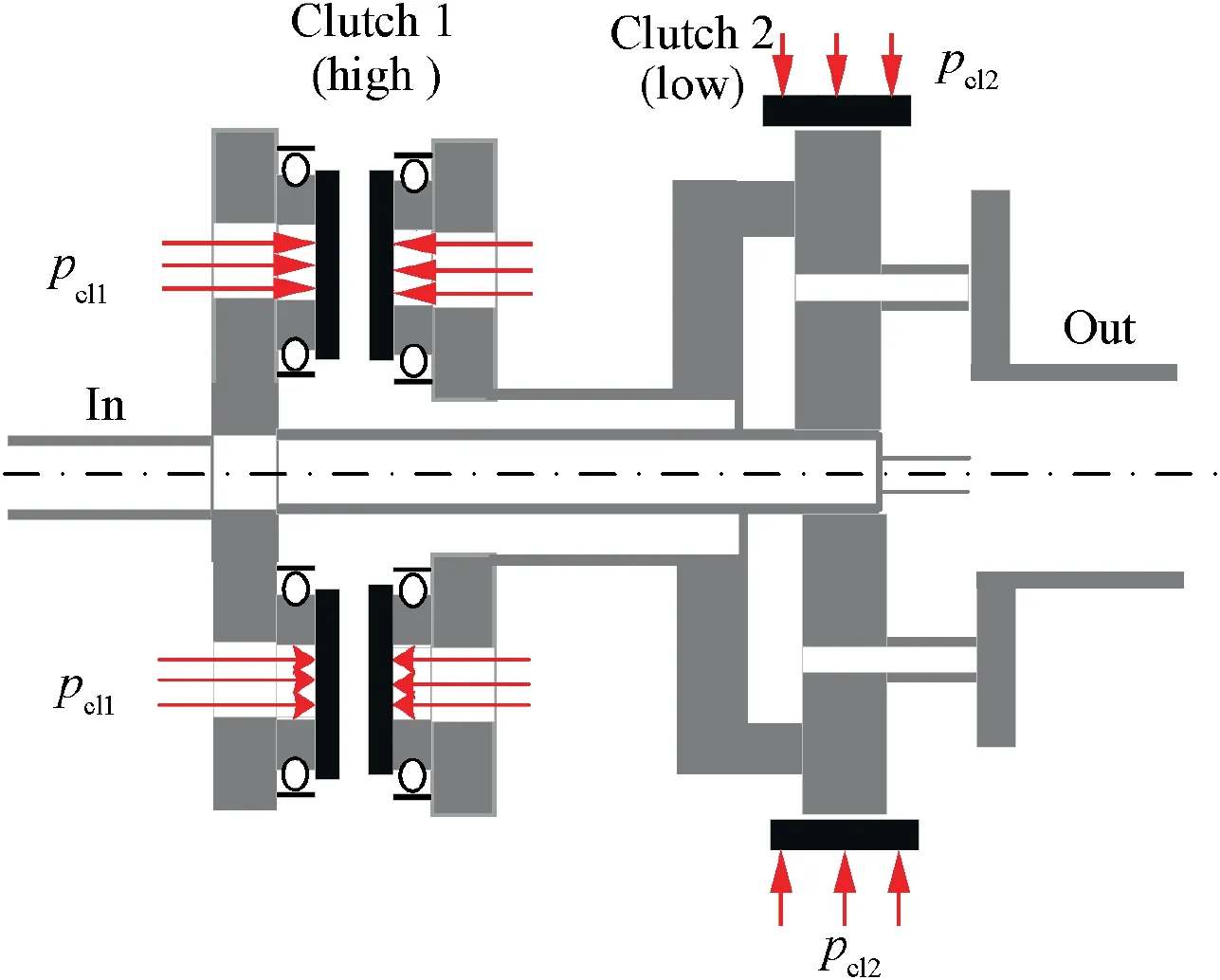
Fig. 1 Diagram of two-speed DCT.

Fig. 2 Kinematic diagram of two-speed DCT.
where nDCTdenotes the gear ratio of DCT. To simulate the dynamics characteristics of DCTs, a rigid body dynamics model is available that consists of the DCT kinematics, the gear rotational inertias and the nonlinear clutch friction torques.4The equations of motion have the form:

where Ω=[Ωi, Ωr]T; M is the inertial matrix, which is associated with the moments of inertia of all DCT components.The generalized force vector is shown in Eq. (4).

where Γiand Γoare input and output shaft torque of DCT;Γcl1and Γcl2are the transmitted clutch torques that are achievable based on a combined Coulomb/viscous model16; Ncgdenotes the number of planet clutches.
According to the above equations, taking engine output torque and rotor demand torque as the inputs,the continuous variation of DCT gear ratio is available through applying different clutch load.
3. Ngdot estimator based on LQG/LTR
Currently,the common control scheme of power turbine speed is cascade PID control.7,8This scheme consists of two control structures,one is based on the gas turbine speed and the other is based on the acceleration of gas turbine rotating (Ngdot).The former has better anti-interference ability, adaptability and control effect than the single PID control method, but it takes much more time to tune the parameters. The latter hardly affects the system natural frequency and allows larger open-loop gain.It is beneficial to improve the dynamic performance and steady-state accuracy. In addition, it is relatively relaxing to adjust the controller parameters.17In terms of the cascade PID control based on Ngdot,Ngdot is unmeasurable,so an online Ngdot estimator is available based on LQG/LTR control method.
LQG/LTR control is a robust control method developed based on modern control theory.18It combines the linear quadratic regulator and the robust characteristics of linear time-invariant Kalman filter. In order to overcome the poor robustness of LQG method,19LTR procedure is applied.Therefore, the whole design is divided into two independent steps:(A)designing the objective feedback loop to have desired function; (B) recovering the transfer function of the objective feedback loop. The design of the LQG/LTR is based upon the following methodology, and the linearized system can be defined by the following State Variable Model (SVM):

where A,B,C and D are coefficient matrixes with appropriate dimensions.Δu,Δx and Δy denote the variations of input vector,state vector and output vector respectively.The input and output vectors are Ngdot and engine output torque Tqe. The state vector contains the relative speed of gas turbine Ng, the relative speed of power turbine Npand Tqe.
In order to eliminate the steady-state error of the control loop, an integral link is applied in the design of the objective feedback loop. Fig. 3 shows the structure of augmented system, Δucis the derivative of Δu and the following model is available:


Fig. 3 Structure diagram of augmented system.
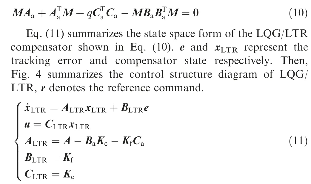
In order to realize the optimal estimation of Ngdot,the real engine output torque (ΔTqe) is selected as the reference command,and the state space equation shown in Eq.(5)is adopted as the prediction model of engine output torque (ΔTqe,p).Therefore, the structure diagram of Ngdot estimator based on LQG/LTR is shown in Fig. 5.
According to the above principles, Ngdot estimator based on LQG/LTR is available.

Fig. 4 Control structure diagram of LQG/LTR.

Fig. 5 Structure diagram of Ngdot estimator based on LQG/LTR.
4. Rotor demanded torque prediction
The transient torque at the tip of the rotor blades contains the variation of control variables and the dynamic information of the helicopter during maneuver flight, which characterizes the power requirement of the helicopter. Thus, it is the most advantageous signal for turboshaft engine to compensate for the disturbance. Unfortunately, the helicopter adopts flexible or semi-rigid and semi-flexible blades in general, resulting in a significant lag in the measurement of the torque at the rotor shaft relative to the change of the control variables,20which is hardly accessible for feedforward compensation. Therefore, it is necessary to predict the rotor demanded torque in advance.
In order to describe the dynamic characteristics of the main rotor model precisely,the Neural Network(NN)is available to obtain the prediction model of rotor demanded torque through offline training. NN usually adopts gradient descent method,conjugate gradient method or quasi-Newton method as training method. Among them, the gradient descent method is the most popular owing to low calculation lost and fast convergence speed. The output of neurons after each iteration is shown in Eq. (12):

Back propagation is adopted to acquire the gradient of weights and biases21,22. Its principle is shown in Fig. 6.Wherein,[σl]′is the derivative of the activation function at hidden layer nodes, and l=nnet-1, nnet-2,· · ·,2 nnetrepresents the number of NN layers.
The Min-batch Gradient Descent (MGD) method divides the training set data into M groups randomly,and each group has Nbtraining sets. J(W,b;x,y) denotes the loss function of each group, which is the training objective of the network.x, y are training and testing samples. W and b represent the weight matrix and the bias matrix of NN.Eq.(13)summarizes the derivative(δl)of the nodes in the lth layer,where ⊗denotes the Hadamard or Schur product.

Fig. 6 Back propagation principle diagram of neural network.


Fig. 7 Relative training error of rotor demanded torque.

The whole NN model consists of 14 input variables and one output variable. In addition, 30 hidden layer nodes is necessary. The integrated rotor/turboshaft engine system is adequately motivated. Then, the output data is normalized and utilized as the training data.Fig.7 summarizes that the relative error of the rotor torque predictive model is less than 0.5%,which is appropriate to predict rotor demanded torque during variable rotor speed.
5. Simulation verification
Fig. 8 summarizes the control structure of the integrated rotor/turboshaft engine system with variable rotor speed based on the Ngdot estimator through LQG/LTR and rotor predicted torque feedforward. As shown, engine output torque Tqeis normalized and then enters into the Ngdot estimator based on LQG/LTR. Ngdot is available online for cascade PID control based on Ngdot to realize the constant speed control of turboshaft engine. Rotor torque predicted module predicts the demanded torques of according to the input variables,which is adopted to compensate for the variation of power turbine speed caused by the rotor torque disturbance during variable rotor speed.In addition,the pitch controller is applied in the flight control system to track flight command. Meanwhile, in order to achieve variable rotor speed, transmission command are accessible to adjust the gear ratio of DCT.Wherein Nprshown in the Fig. 8 denotes the reference command of Np,Wfbis the fuel flow,Tqr,prepresents the predicted rotor demanded torque.

Fig. 8 Cascade PID control structure diagram of Ngdot estimator based on LQG/LTR for integrated helicopter/engine with variable speed.
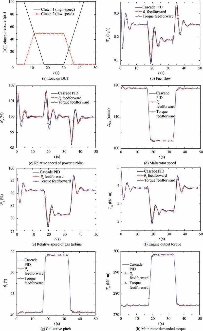
Fig.9 Comparison of cascade PID control based on Ngdot estimator with or without torque feedforward for variable speed helicopter/engine at constant flight condition.

Fig. 9 (continued)
Next,the control effect of the control method based on the Ngdot estimator through LQG/LTR and rotor predicted torque feedforward at the flight altitude command of 600 m and the forward speed command of 118 m/s, and compared with cascade PID control based on Ngdot and the one combined with collective pitch feedforward. Fig. 9(a) summarizes the load on the two-speed DCT. As shown, when the clutch executes upshift, the low-speed clutch pressure gradually decreases to zero. Meanwhile, the high-speed clutch pressure linearly increases from 0 to 100 psi (1 psi=6894.757 Pa) to lock the gear. In reverse, the downshift can be executed. The simulation results are shown in Figs. 9(b)-(i).
As shown in Figs. 9 (c) and (d), when the load shown in Fig. 9(a) is applied to the two-speed DCT, the rotor speed can vary by 38% continuously with these three control methods on the premise that the power turbine speed keeps around 100%, which realizes the simulation of variable rotor speed.Fig.9(k)summarizes that compared with the cascade PID control method based on Ngdot,the one combined with collective pitch feedforward control can reduce the overshoot of power turbine speed by 7% ([(1.67-1.55)/1.67]×100%=7%) effectively during variable rotor speed. Nevertheless, the cascade PID control method based on Ngdot and rotor predicted torque feedforward could decrease the overshoot of power turbine speed by 24% ([(1.67-1.27)/1.67]×100%=24%). It proves that the response speed of turboshaft engine is faster,and the dynamic performance is superior. The reason is that the main rotor torque changes sharply during variable rotor speed. In this case, rotor predicted torque feedforward compensates for the disturbance of wide variation in rotor demanded torque on power turbine speed through predicting the rotor demanded torque in advance, which reduces the overshoot of power turbine speed significantly. Figs. 9 (d)and(g)summarize that when main rotor speed ΩMRdecreases continuously, it is necessary to increase the collective pitch θ0to ensure that the main rotor can provide adequate thrust.In terms of the main rotor,the rotor speed decreases,resulting in the reduction of rotor demanded power, which leads to the rapid decrease of fuel flow Wfband the output power of turboshaft engine. Since the turboshaft engine adopts the constant speed control scheme, that is, the power turbine speed maintains around 100%, the engine output torque decreases accordingly to reduce the output power,as shown in Fig.9(f).
In order to validate the robustness performance of the control method,the simulation test under variable flight condition is carried out. The flight altitude command is 1000 m, and the load of two-speed DCT is consistent with that of Fig. 9 (a).Fig. 10(a) shows the forward speed command. At t=10 s,νccommand accelerates linearly from 119 m/s to 125 m/s,and remains unchanged between 15 s and 45 s. 5 s later, νccommand decelerates to 119 m/s and stays constant until the end of the simulation. Figs. 10 (b)-(h) summarize the simulation results.

Fig.10 Comparison of cascade PID control based on Ngdot estimator with or without torque feedforward for variable speed helicopter/engine at variable flight condition.
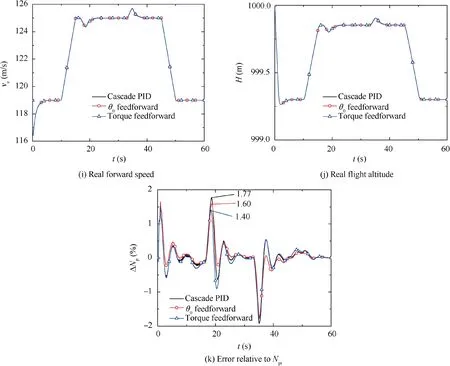
Fig. 10 (continued)
As shown in Figs. 10 (a) and (d), at t=10 s, the forward speed accelerates. Thereafter, the rotor speed decreases from 176 r/min to 110 r/min. At t=33 s, the rotor speed increases rapidly to 176 r/min, and the forward speed decelerates 10 s later. During the rotor downshift/forward speed acceleration phase, the relative speed of the power turbine shown in Fig. 10 (c) is less than 100%. The reason is that the thrust increases at acceleration, while the rotor speed decreases at the same time. In order to keep the forward speed constant,it is necessary to increase the collective pitch (as shown in Fig. 10 (g)). Fig. 10 (c) summarizes that compared with cascade PID control based on Ngdot and the one combined with collective pitch feedforward, the cascade PID control method based on Ngdot and rotor predicted torque feedforward could reduce the overshoot of power turbine speed by about 20%,which possesses excellent robustness performance. Figs. 10(b)and(e)show the fuel flow and the relative speed of gas turbine respectively.As shown in Fig.10(e),the relative speed of gas turbine is less than 102%, and the maximum value of engine output torque is no more than 5 kN·m through all of these three control methods, which is beneficial to maintain the service life of the turboshaft engine.
6. Conclusions
The research on control method for the integrated rotor/turboshaft engine with variable rotor speed is conducted.Wherein, a cascade PID control method based on the Ngdot estimator through LQG/LTR and rotor predicted torque feedforward is proposed.The following conclusions can be drawn.
(1) The main rotor speed can vary continuously by 38%through the application of two-speed DCT.
(2) Compared with the cascade PID control method based on Ngdot,the one combined with collective feedforward control can effectively reduce the overshoot of power turbine speed by 7% during variable rotor speed.
(3) Compared with the cascade PID control method based on Ngdot,the one combined with rotor predicted torque feedforward could reduce the overshoot of power turbine speed by 24%. It is beneficial to compensate for the disturbance of wide variation in rotor demanded torque on power turbine speed and realize the fast response control of turboshaft engine with variable rotor speed.
(4) The control method will be validated in the semiphysical simulation platform and micro turboshaft engine.
Acknowledgements
The work has been co-supported by the National Natural Science Foundation of China, China (Nos. 51576096 and 51906102), Qing Lan and 333 Project, the Fundamental Research Funds for the Central Universities, China (No.NT2019004), National Science and Technology Major Project China(No.2017-V-0004-0054),Research on the Basic Problem of Intelligent Aero-engine, China (No. 2017-JCJQ-ZD-047-21), China Postdoctoral Science Foundation Funded Project,China (No. 2019M661835) and Aeronautics Power Foundation, China (No. 6141B09050385).
 CHINESE JOURNAL OF AERONAUTICS2020年7期
- CHINESE JOURNAL OF AERONAUTICS的其它文章
- An experimental method for squealer tip flow field considering relative casing motion
- A novel none once per revolution blade tip timing based blade vibration parameters identification method
- Highly efficient computation method for hazard quantification of uncontained rotor failure
- Optimal motion cueing algorithm for accelerating phase of manned spacecraft in human centrifuge
- Effective control allocation using hierarchical multi-objective optimization for multi-phase flight
- Fault-tolerant control and vibration suppression of flexible spacecraft: An interconnected system approach
