Optimizing accuracy of a parabolic cylindrical deployable antenna mechanism based on stiffness analysis
Hang XIAO, Shengnan LYU, Xilun DING
KEYWORDS Accuracy analysis;Cable-driven;Deployable antennas;Optimization;Stiffness analysis
Abstract Accuracy of the fitted surface is of great importance to the performance of deployable antennas utilized in space.This paper proposes a stiffness analysis based fitting accuracy optimization method for achieving the optimal parameters of the parabolic cylindrical deployable antenna mechanism. The stiffness matrix of the proposed cylindrical antenna mechanism is established by assembling the stiffness of beams and tension cables. Structural deformations of the mechanism are calculated where the tensioned cable is substituted by a 2-node truss element and an equivalent force acting on the joint.Consideration of the tensity of tension cables,namely tensioned or slack,is transformed into a typical linear complementarity problem. Comparison between structural deformations of the mechanism fixed at different points is performed. Sensitivities of the geometric and structural parameters on fitting accuracy are investigated. Influence of force of the driven cable on structural deformations of antenna operated in different orbits is conducted.A fitting optimization method is proposed to minimize the structural deformations subject to constraints on volume and mass. Simulation result shows that the fitting accuracy of the antenna mechanism is improved significantly through the optimization.The proposed method can be utilized for the optimal design of other deployable mechanisms constructed by joining rigid links.
1. Introduction
Deployable antennas, which can be folded compactly for easy transportation and deployed to a large predetermined shape in orbit, are largely demanded with the rapid development of space industry.1,2One of the most commonly used antennas is the deployable mesh antenna for its lightweight, large aperture, and simple structure.3-5
The deployable mesh antenna consists of a lightweight metal reflector and a deployable supporting mechanism. Accuracy analysis of the cable networks of the metal reflector6-9has been well studied, however accuracy of the supporting mechanism attracts less attention. Several deployable mechanisms composed of Myard,10Bennett11,12and Bricard13linkages, which are able to deploy to fit different surfaces, can be utilized as the supporting structures of antennas.As we know,the deployable supporting mechanism cannot be perfect rigid. For the large scale of the antenna, the structural deformations of the mechanism are not ignorable.Deformations of the mechanism change the connections of the metal reflector, which significantly reduces the accuracy of the antenna.14-16As a result,fitting accuracy of the supporting mechanism,which is determined by the structural deformations, is a key problem to be investigated in this paper.
Structural deformations of the antenna can be obtained through stiffness and compliance analysis. Ding et al.17,18derived the compliance matrix of a spatial elastic beam by using screw theory and Lie groups. Shan,19Kaveh and Davaran20derived the stiffness matrix of the basic components from a three-nodes beam; and condensed the rotational degrees to reduce the dimension of the stiffness matrix. Xiao et al.21proposed an equivalent mechanical model for solving the stiffness of a membrane antenna frame supported by compliant booms and tensioned with cables. Kwan and Pellegrino22,23developed the equilibrium and flexibility matrices for macro elements, which were then assembled as the overall matrices of the deployable structures. Gantes et al.24established an equivalent continuum model for the stiffness prediction of deployable structures.
To improve the performance of the mechanism, geometric and structural parameters should be optimized during the design process. Several studies conducted the optimal design of deployable structures. Refs. 25,26 focused on optimization of the parameters of the cross section to minimize the weight of deployable structures. Multi-objective optimal designs of deployable structures were performed to seek for the optimum weight and volume.27-29Guo et al.30,31presented a method for obtaining good surface accuracy which provides the optimal pretensions corresponding to a desired shape of cable-rib tension deployable antenna frame.
A deployable mechanism, which can approximate a cylindrical surface in the fully deployed configuration, has been adopted as the supporting structure of an antenna in our previous works.32,33In this paper,tension cables are introduced to improve the stiffness performance of the antenna;driven cable is utilized to deploy the mechanism. The optimal design of a parabolic cylindrical deployable mechanism (PCDM) of an antenna is presented with considering the elastic deformations of the supporting mechanism. Unidirectional characteristic of cables requires the analysis of the tensity of tension cables.Effects of the driven cable on the fitting accuracy, which is helpful on adjusting the accuracy of the PCDM operating on different orbits, are presented. Due to the constraints of both volume and mass, geometric and structural parameters have been considered at the same time in the optimization of fitting accuracy.
The rest of this paper is organized as follows. Section 2 introduces the description of the cable-driven PCDM. In Section 3, the stiffness analysis of the mechanism is performed.Section 4 derives the structural deformations of the proposed deployable mechanism; two cases with different fixed points are investigated. Section 5 discusses the influence of parameters on the fitting accuracy of the deployed surface.The optimization model is established;the optimal parameters which lead to the minimum structural deformations are obtained in Section 6.
2. Description of the parabolic cylindrical deployable antenna mechanism
As illustrated in Fig. 1, a general satellite system consists of one satellite,two solar arrays,and a large deployable antenna.The antenna can receive and transmit signals for communication. A PCDM is used as the supporting mechanism of the antenna. Metal reflector is attached to the deployable mechanism by cables. The deployable mechanism is connected to the satellite through a fixed arm.
The PCDM is constructed by linking Bennett linkage units via scissor elements. As shown in Fig. 2(a), when the mechanism is deployed, it can approximate a parabolic cylindrical surface. The deployable mechanism consists of two identical strips. Each strip has four big and three small Bennett units.Aperture of the mechanism is 10 m; height and width are 1.25 m and 5 m, respectively. The joints, which are marked as solid circles, are located precisely on the parabolic cylindrical surface. Side view of the mechanism is shown in Fig. 2(b).As can be seen from the figure, directrix of the cylinder is a parabola. Kinematic analysis of the mechanism has been performed in Ref. 33 in detail. Known from Ref. 33, once O0M1and M2M4are given, geometric parameters of a specific parabolic cylindrical mechanism can be calculated.
Fig. 3 displays the top view of the deployable mechanism.Light-weight tension cables (described by dashed lines) are introduced to enhance the stiffness without a significant increment in weight. Driven cable is utilized to deploy the mechanism. The figure also shows the distribution of the cable.The mechanism deploys when the driven cable is pulled along the direction of the arrows. At the fully deployed stage, an extra force, which improves the fitting accuracy of the mechanism,is applied by the driven cable on joints of the mechanism.Pulleys at the joints are used to adjust the direction of the cable.
As shown in Fig. 4, friction, between the driven cable and the pulley, causes the cable tension on the passive side to be less than that on the active side.The friction can be calculated with the Hertz contact method. The relationship of the cable tension on two sides of a pulley is
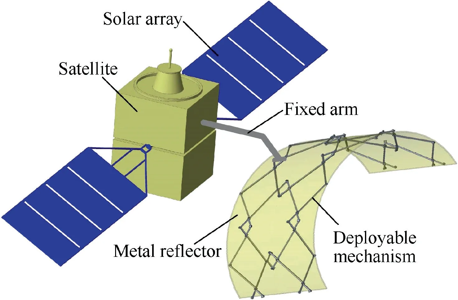
Fig. 1 A general satellite system.
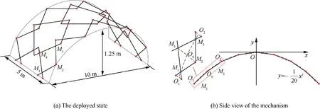
Fig. 2 Parabolic cylindrical deployable mechanism.

Fig. 3 Driven cable and tension cables.

Fig. 4 Friction in cable-pulley system.

where μ=0.28 is the friction coefficient and φ is the angle swept by the cable.
40. She killed, cooked, and ate him: The witch is a cannibal. Cannibalism105 is one of the most reviled106 crimes in the world. It is considered the quintessential expression of savagery107 and evil. Charges of cannibalism have long been used as justifiable108 reasons for enslaving or destroying a population or person.
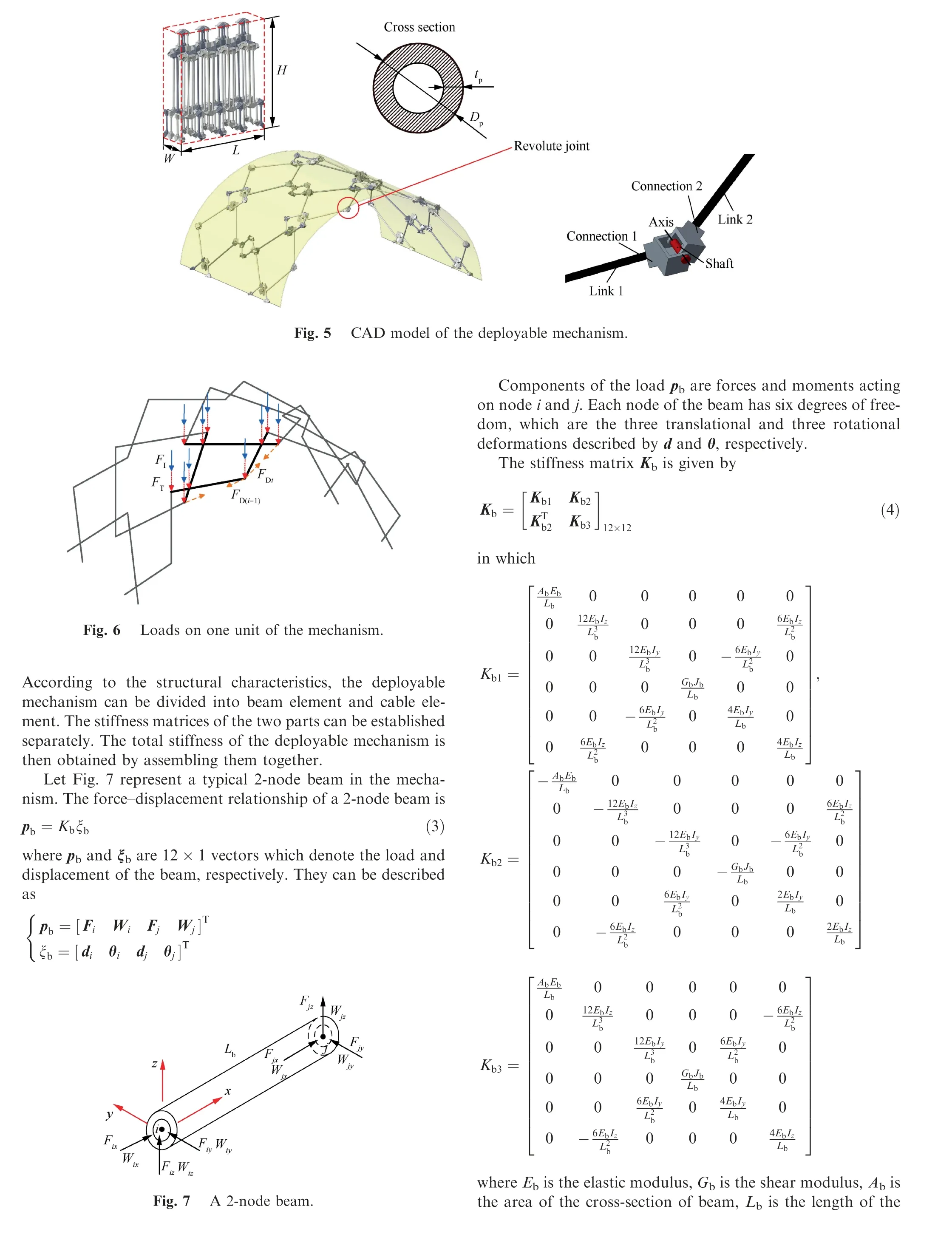
The structural design of the mechanism is accomplished,the CAD model is established as shown in Fig. 5. Both the folded and the deployed configurations of the deployable mechanism are displayed in the figure. Hollow carbon fiber pipes are adopted as links; the diameter and thickness of the pipes are denoted as Dpand tp, respectively. Each end of the link is glued to a connection. Two adjacent connections are linked by a shaft which forms a revolute joint.The connections and shafts are both made of steel.The degree of freedom of the deployable mechanism is one which indicates that the mechanism is transformed into a structure when any one of the joints is locked. To obtain better stiffness, in practice, all joints are mechanically locked when the mechanism is fully deployed.The envelop volume of the folded mechanism is L×W×H.W and L are decided by the size of the connection joint; while H can be calculated from O0M1and M2M4.
When the antenna is operating in orbit, the tension of the metal reflector, the force of the driven cable and the inertial load are all applied on the deployable mechanism. Generally,the tension of the metal reflector is constant. We assume that the average tension acting on each joint is FT. Magnitude of the force of driven cable, FD, is adjustable. The direction of the force is along the driven cable.Due to the friction between the driven cable and the pulley,the force of the driven cable,FDiand FD(i-1), applied on the i-th unit of the PCDM can be obtained by Eq. (1). Inertial load applied on the deployable mechanism, which varies with the orbit radius, is expressed as

where M,r,and v are the mass,the orbit radius and the linear velocity of the mechanism, respectively. The inertial load,which is denoted as FI, is evenly distributed on each joint of the mechanism. FI=FWI/n, where n is the number of joints.Fig. 6 illustrates how the loads are distributed on one unit of the mechanism.
3. Stiffness analysis of the PCDM
3.1. Stiffness analysis of the beams and tension cables


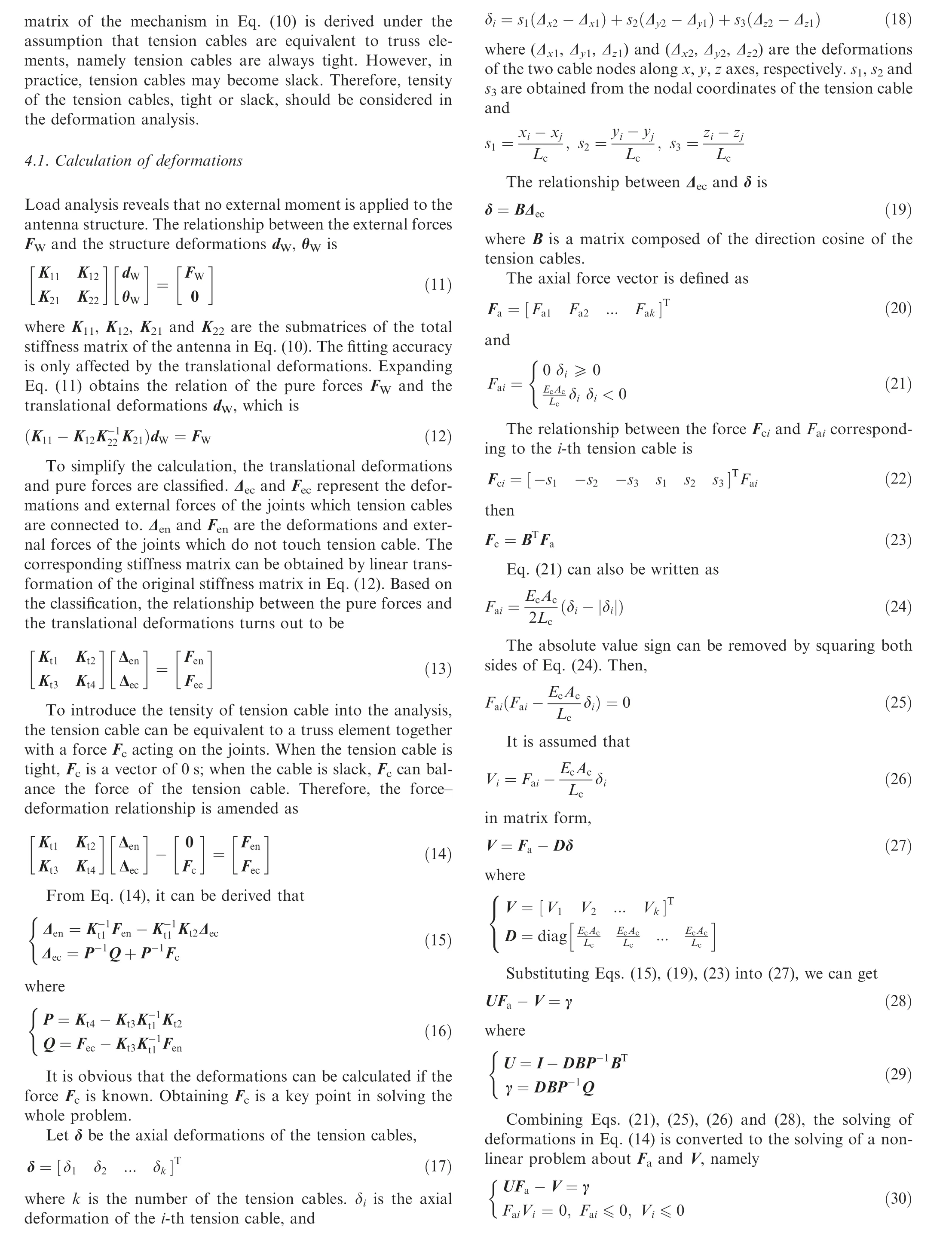
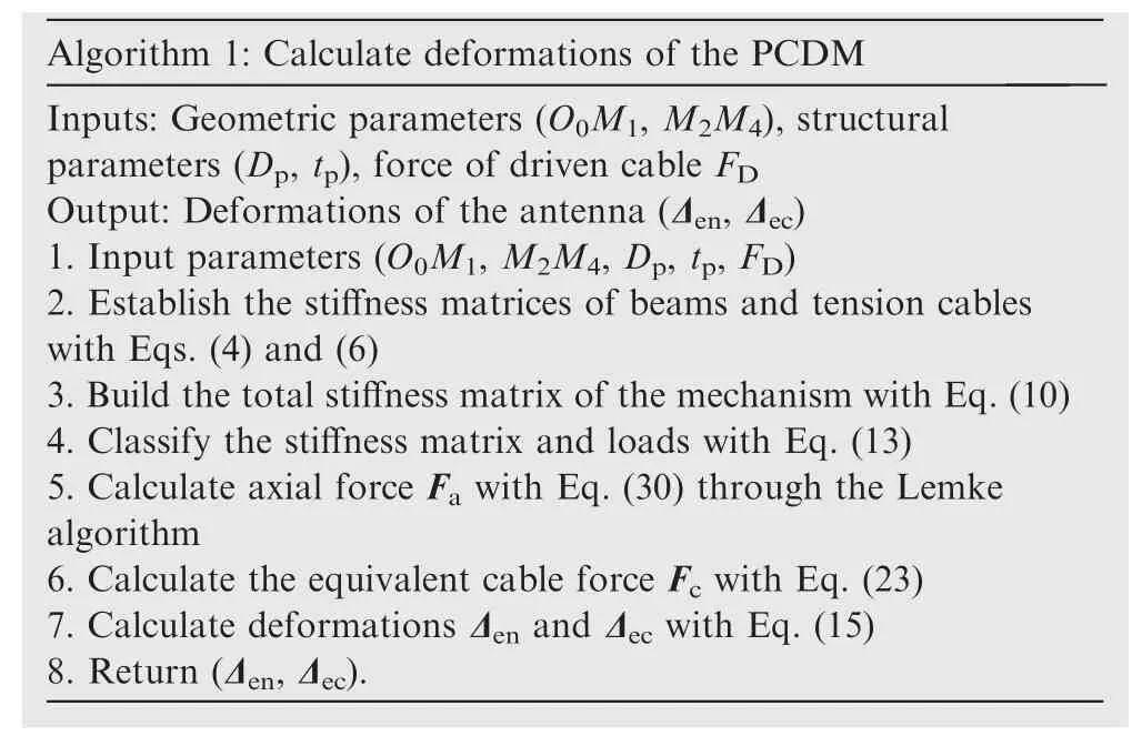
Eq.(30)describes a typical linear complementarity problem which can be solved by the Lemke complementary pivot method.34The following algorithm 1 presents the process of deformation calculation.
?
4.2. Definition of fitting accuracy
From the previous subsection,the deformation of each joint is obtained as

where Δxi,Δyiand Δziare the deformations of joint i along x,y,z axes, respectively.
The fitting accuracy of the antenna structure, which is quantified as the deformation root mean square of all joints,30is defined as

4.3.Deformations of the PCDM under two different fixed points
The PCDM is connected to the satellite through some fixed points. For a certain deployable mechanism, different fixed points result in different deformations. Two groups of fixed points of the mechanism are analyzed. There are two fixed points in each group. Points in the first group are at the outer end; in the second group, they are at the center of the mechanism.
Table 2 shows the material parameters of beams and cables.Design parameters and external loads of the mechanism are presented in Table 3. It is assumed that the satellite is operating in geosynchronous orbit. Deformations of the mechanism are calculated with the given parameters.
Fig. 10(a) shows the deformation of the mechanism which is fixed at the outer endpoints 1 and 2. The red line represents the original mechanism without deformation, the blue line indicates the deformed mechanism. The mechanism is bent downward about the fixed joints under the action of external loads.The deformation is larger when the joint is farther away from the fixed joints. The maximum deformation occurs atjoint 60, which is 16.6 mm. The fitting accuracy of the mechanism is 8.91 mm.

Table 2 Material parameters of beams and cables.

Table 3 Design parameters and loads.
In the second case, the mechanism is fixed at the points on joints 29 and 30, which are located at the center of the mechanism. The deformation is illustrated in Fig. 10(b). The result displays a high degree of symmetry about the fixed points.The maximum deformation is 1.51 mm occurring at the farthest joints 4 and 60. The fitting accuracy is 0.785 mm.
The maximum deformation and fitting accuracy of the PCDM fixed at the outer endpoints is much larger than those fixed at the center points,which means the latter case performs a better stiffness performance. The mechanism is fixed at the center in the following analysis for a better fitting accuracy.
5. Influences of parameters on the fitting accuracy of PCDM
5.1. Influences of the geometric parameters
Due to the space limitation of launch vehicles, in the fully folded configuration, the height of the mechanism, which is determined by the geometric parameters, should be smaller than a certain value.
Influence of O0M1, in the range of 800 mm to 1200 mm, is studied while other parameters remain the value in Table 3.The changes in fitting accuracy σ and height H with respect to O0M1are plotted in Fig.11(a).As can be seen from the figure, both the fitting accuracy and height decrease with the increasing of O0M1.
Fig.11(b)describes the variations of σ and H with respect to the change of M2M4. The value of fitting accuracy increases while the height declines with the increment of M2M4, which reveals a higher storage space is acquired for a better fitting accuracy.When O0M1and M2M4increase 100 mm,the changes of the fitting accuracy corresponding to O0M1and M2M4are 5.75×10⁻⁵m and 1.07×10⁻⁵m, respectively. Compare to O0M1,M2M4has fewer influence on the fitting accuracy.
5.2. Influences of the structural parameters
Mass of the mechanism is determined by the structural parameters when the geometric parameters are fixed.Due to the payload capacity of launch vehicles, mass should also be considered in the design. Mass of the mechanism can be expressed as

Fig. 10 PCDM is fixed at two different joints.
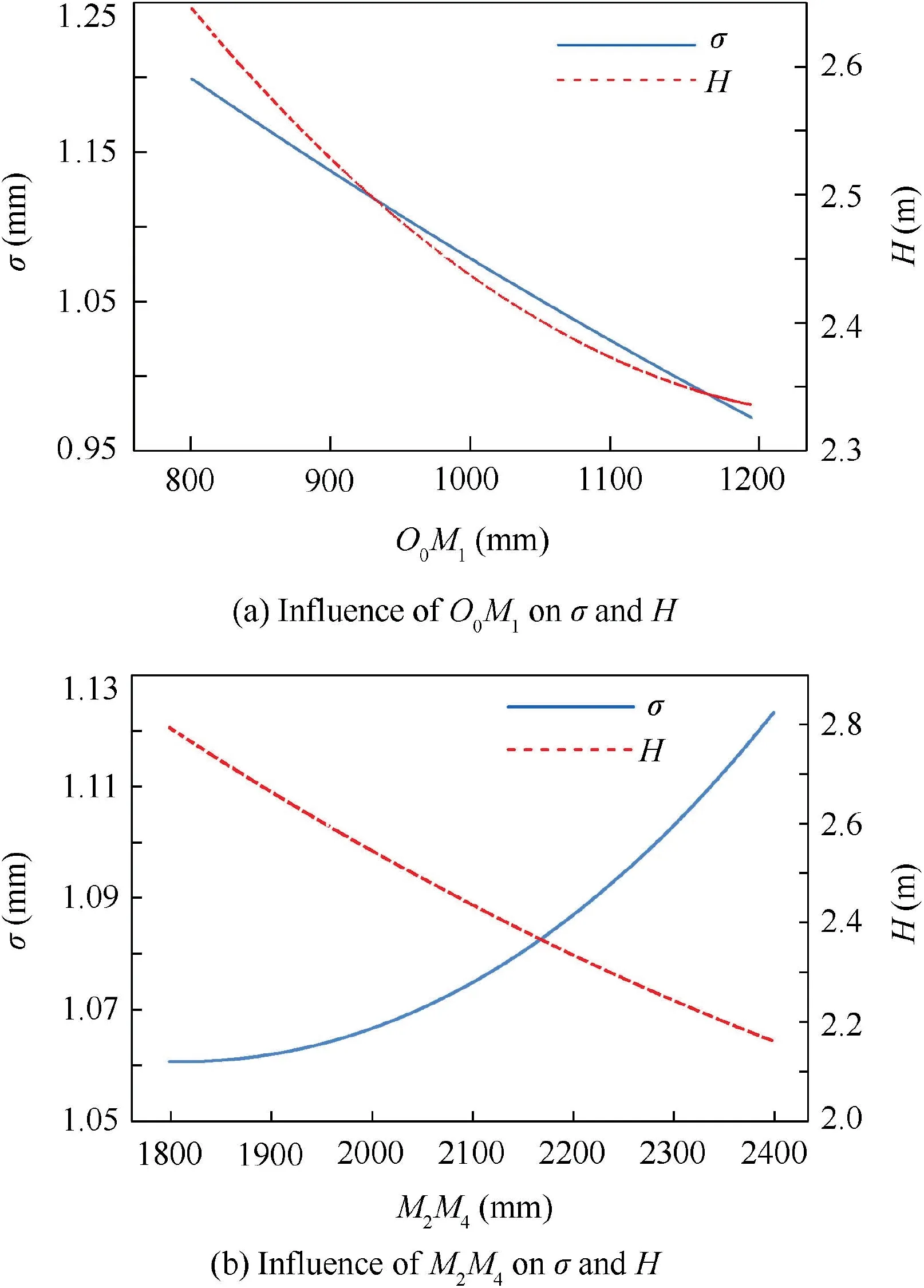
Fig. 11 Influences of O0M1 and M2M4 on σ and H.

where ρband ρcare the density of the beam and tension cable respectively. Lbiand Lcirepresent the length of the i-th beam and tension cable. mJiis the mass of the i-th connecting joint.Fig. 12(a) and (b) illustrate the changes of the fitting accuracy σ and mass M with respect to the structural parameters,namely the diameter Dpand thickness tpof the pipes. When Dpchanges from 80 mm to 130 mm, the value of fitting accuracy decreases by 52.7% and the mass increases by 49.3%.Meanwhile, σ decreases by 19.1% and the mass increases by 82.6% with tpfrom 6 mm to 18 mm. It can be concluded that it is more efficient to increase Dprather than tpfor obtaining better fitting accuracy and lower mass.
5.3. Influences of driven cable force on deformation
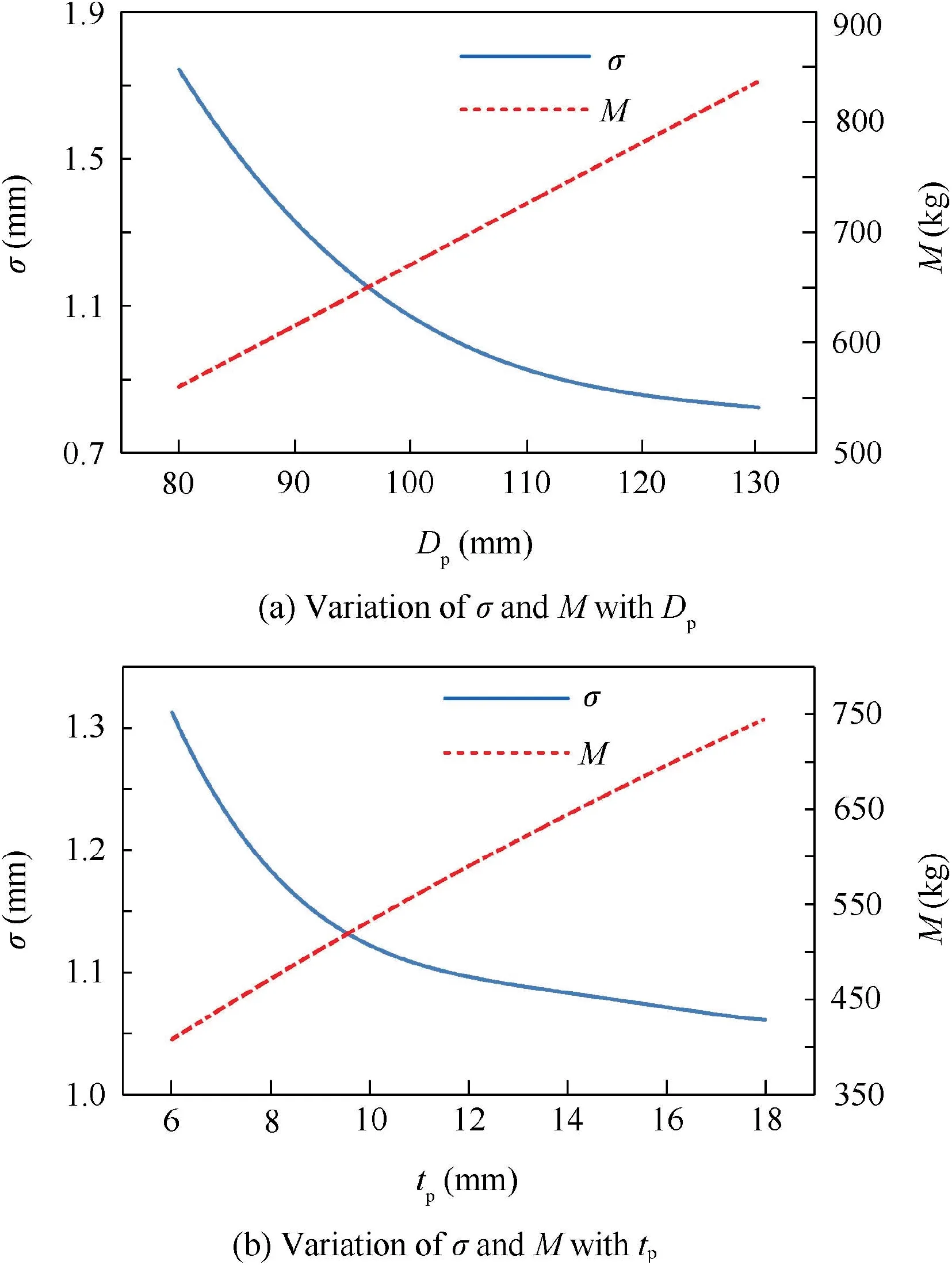
Fig. 12 Variations of σ and M with Dp and tp.
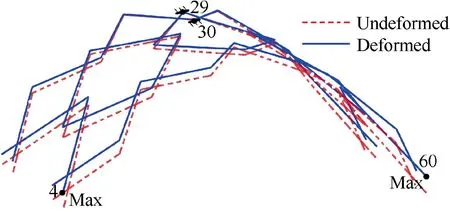
Fig. 13 Deformations under the action of FD.
As shown in Fig. 13, the mechanism deforms when the driven cable force FDis applied whereas there is no FTand FI. The mechanism is bent upward about the fixed joints, which is opposite to that under the action of FTand FI. The deformation result reveals that the force of the driven cable can be utilized to adjust the fitting accuracy when FTand FIare applied on the mechanism.
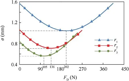
Fig. 14 Variation of σ with respect to FD in different orbits.
Fig. 14 indicates the variation of the fitting accuracy with respect to the force of the driven cable when the satellite operates in three different orbits. The orbit radii are r1=2.5×10⁷m, r2=3.6×10⁷m, and r3=5×10⁷m,respectively. The fitting accuracy decreases firstly with the increment of FD; then increases after the fitting accuracy reaches the minimum value. The minimum value of fitting accuracy increases with the decreasing of orbit radius. Therefore, when the orbit radius, geometric and structural parameters are all given,by adjusting the force of the driven cable,FD,an optimal fitting accuracy can always be obtained.
6. Optimization of the fitting accuracy of PCDM
Influences of the geometric parameters O0M1and M2M4, the structural parameters Dpand tp, the force of the driven cable FDon fitting accuracy have been studied in the last section.To construct a parabolic cylindrical deployable mechanism whose aperture, height and width are 10 m, 1.25 m and 5 m,respectively,an optimal set of geometric parameters,structural parameters, and force of driven cable should be achieved to guarantee the stiffness performance of the antenna.
6.1. Optimization model
To construct a specific deployed shape,the geometric parameters, the structural parameters, and the force of the driven cable are selected as design variables. The optimization model is formulated as
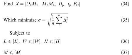
The lower and upper bounds of the design variables are presented in Table 4. In order to get a better stiffness performance, the optimization object is to minimize the value of the fitting accuracy σ.
Eqs. (36) and (37) represent the volume and mass constraints, respectively. Due to the limitation of space of launch vehicles, the envelop size of the mechanism at the folded state should be smaller than [L], [W] and [H]. Considering the payload capacity of launch vehicles, the total mass of the mechanism should be less than [M]. The design constraints are presented in Table 5.

Table 4 Lower and upper limits of the variables.

Table 5 Design constraints.
6.2. Optimal result
Genetic algorithm(GA)is a metaheuristic to simulate the process of natural selection.35GA has been widely used in the optimal design of different engineering fields.26,36,37The procedures of GA include encoding, initialization, fitness calculation, ranking, selection, mutation, and crossover. Table 6 shows the parameters of GA. The material parameters are given in Table 2. The satellite operates in geosynchronous orbit and the inertia load, FI, can be calculated by Eq. (2).The tension, FT, of the metal reflector is assumed as 3 N.The envelope size of the mechanism at the folded state can be calculated with the variables O0M1and M2M4. The mass of the mechanism is obtained with the length of beams and variables Dpand tp. The fitting accuracy can be calculated according to the above analysis. The optimal result is then obtained by using GA under the constraints of mass and volume. Table 7 gives the result of the optimal design.
Before optimization, the fitting accuracy is 1.09 mm. The value of the fitting accuracy decreases to 0.26 mm after optimization. Deformations of joints 1 ~32 at the left part of the mechanism are presented in Fig. 15 (joints are numbered as shown in Fig. 3). The right part performs the same due tothe symmetry of the mechanism. As can be seen in the figure,joint 4, the farthest joint from the fixed joints, generates the maximum deformation. Through the optimization, the maximum deformation decreases from 2.13 mm to 0.48 mm.
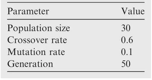
Table 6 Parameters of GA.

Table 7 Result of the optimal design.
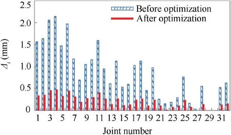
Fig. 15 Deformations of joints 1 ~32.
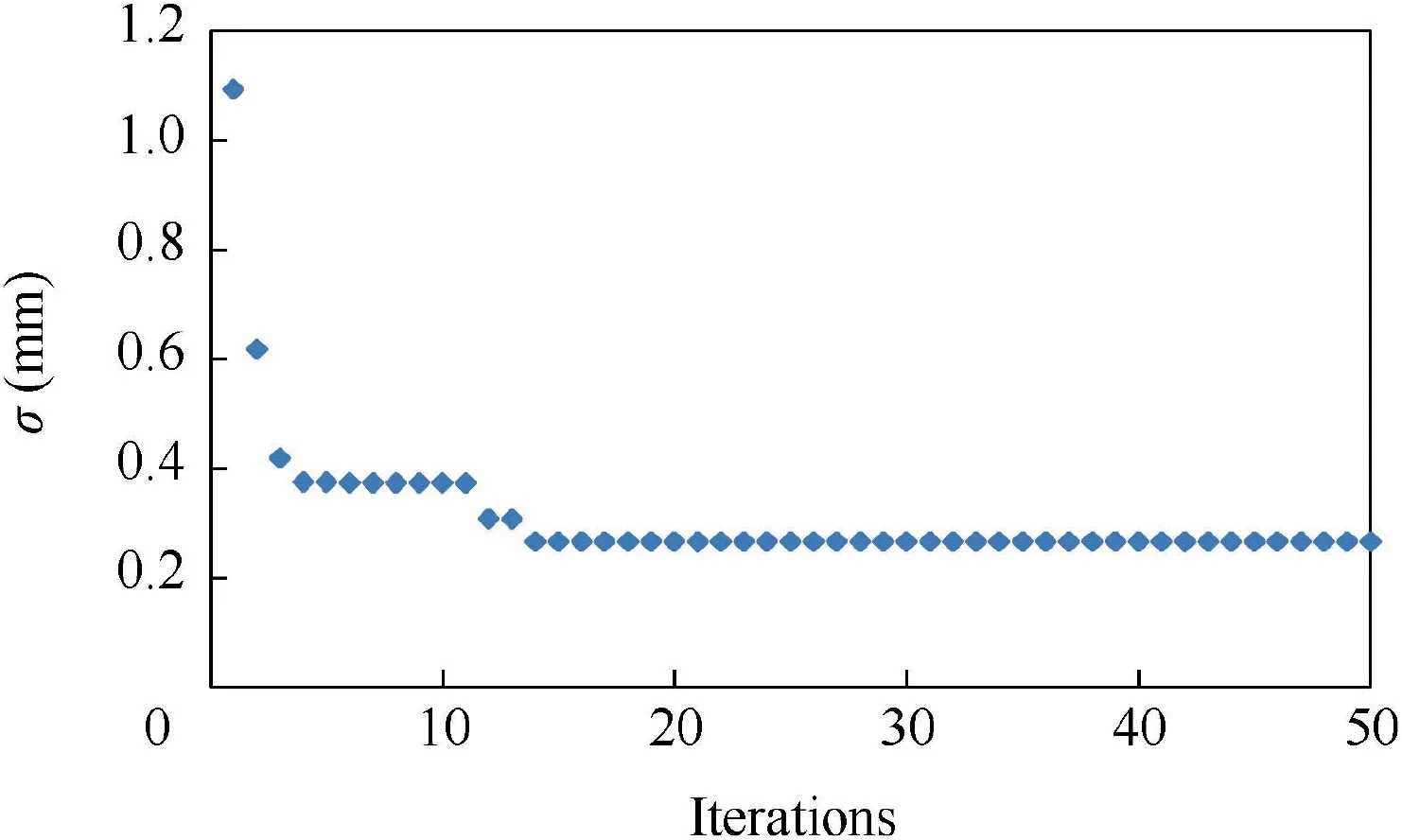
Fig. 16 Iteration process of optimization.

Table 8 Result of fitting accuracy adjustment.
Fig. 16 illustrates the iteration process of the fitting accuracy of the mechanism.The value of fitting accuracy decreases sharply in the first 13 iterations.Initially,the fitting accuracy is 1.09 mm at the initial stage and it finally converges to 0.26 mm.The optimal design has significantly improved the fitting accuracy of the mechanism.
The configuration and mass of the mechanism are determined with the obtained optimal geometric and structural parameters. The inertia load varies when the satellite operates in different orbits, which will result in the change of fitting accuracy. The force of driven cable can be used to adjust the deformations. As shown in Table 8, values of fitting accuracy in different orbits r1=2.5×10⁷m, r2=3.6×10⁷m, and r3=5×10⁷m, decrease significantly after the adjustment of the force of driven cable. The optimal forces of driven cable corresponding to three different orbits are 77.2 N, 53.7 N and 40.1 N, respectively. For a given mechanism in different orbits, it is an efficient way to obtain the optimal fitting accuracy by adjusting the force of driven cable.
7. Conclusion
(1) This paper presents the fitting accuracy optimization of a parabolic cylindrical deployable antenna mechanism with tension cables and a driven cable on the basis of stiffness analysis.Stiffness matrix of the PCDM consists of the stiffness of beams and tension cables. In this matrix, the tensioned cables are equivalent to 2-node truss elements.To consider the tensity of tension cables,namely tensioned or slack, the calculation of the structural deformations is transformed into the linear complementarity problem.
(2) The central joints 29 and 30 are selected as the optimal set of fixed points of the PCDM through the comparison of structural deformations under two options. Sensitivity analysis of parameters on fitting accuracy reveals that geometric parameters affect little on fitting accuracy while structural parameters have significant influence with a great increase of weight.
(3) A fitting optimization method,which can obtain a set of optimal geometric, structural parameters, and force of driven cable,for minimizing the structural deformations of the mechanism under the constraints of volume and mass, has been proposed. Simulation result verifies that fitting accuracy of the antenna has been improved significantly by using the proposed optimization method.
(4) In practice,the optimized antenna,whose geometric and structural parameters are already fixed,could operate at different orbits. In this case, the best fitting accuracy of the antenna can be achieved by adjusting the driven cable. Furthermore, not only suitable for optimizing the parabolic cylindrical deployable antenna, the stiffness analysis based optimization method proposed in this paper can also be applied to improve the design of other deployable mechanisms which are constructed by joining rigid links.
Acknowledgement
This work has been supported by the National Natural Science Foundation of China (No.51635002) (Key Program) and No.51605011.
 CHINESE JOURNAL OF AERONAUTICS2020年5期
- CHINESE JOURNAL OF AERONAUTICS的其它文章
- Experimental of combustion instability in NTO/MMH impinging combustion chambers
- Three-line structured light vision system for non-cooperative satellites in proximity operations
- Remaining useful life prediction of aircraft lithium-ion batteries based on F-distribution particle filter and kernel smoothing algorithm
- Flow characteristics around airfoils near transonic buffet onset conditions
- Experimental investigation of flow and distortion mitigation by mechanical vortex generators in a coupled serpentine inlet-turbofan engine system
- An improved prediction model for corner stall in axial compressors with dihedral effect
