Experimental of combustion instability in NTO/MMH impinging combustion chambers
Anlong YANG, Bin LI, Yu YAN, Shuaijie XUE, Lixin ZHOU
Science and Technology on Liquid Rocket Engine Laboratory, Xi’an Aerospace Propulsion Institute, Xi’an 710100, China
KEYWORDS Atomization;Combustion stability;Impinging jet injector;Klystron effect;Liquid rocket engine
Abstract This paper presents an experimental study into dynamics of chamber pressure and heat release rate during self-excited spinning and standing azimuthal mode in NTO/MMH (nitrogen tetroxide/monomethylhydrazine) impinging combustion chambers. Nine cases including two combustion chamber configurations were conducted. The operating conditions of all unstable cases were located in the instability region according to Hewitt empirical correlation. The results show that chamber pressure oscillations keep pace with the corresponding OH*chemiluminescence intensity over the whole combustion region in the spinning and standing modes. It is indicated that the Rayleigh index is positive over the whole combustion area in all the unstable cases. A significant supersonic flame front structure of the first-order spinning mode was found in a cylindrical chamber, which means that a detonation wave could exist in the cylindrical chamber without a center body.The pressure and heat release rate oscillations at the pressure node are nonnegligible although their amplitudes are lower than those at the pressure antinode in the first-order standing mode with an annular chamber.Besides, the dominant frequency of pressure and heat release rate oscillations at the pressure node is twice as high as that at the pressure antinode.
1. Introduction
Combustion instabilities generated by the coupling of heat release and chamber pressure in the combustor are very complicated and dangerous phenomena in high performance devices like jet engines, ramjets engines and liquid rocket engines. These powerful combustion instabilities often lead to failure and in extreme cases the destruction of the system,because they interrupt original energy supplies,generate undesired intense pressure fluctuations, and result in excessive heat transfer to combustor walls and injector plates. Although research on acoustic combustion instabilities in rocket engines is quite intense worldwide since the 1940s,1,2prediction of these processes at the design stage is still a huge challenge,because of the complexity of the problem, the generally inaccessible environment of the rocket engine combustion chamber, and the lack of appropriate diagnostic techniques available to study the problem.
Azimuthal modes are typically the most unstable and dangerous in combustion instabilities because it is only weakly damped in thrust chambers. However, investigation of azimuthal instabilities remains a scientific challenge since it requires a full combustion chamber configuration whose diameter is directly related to the time and length scales of azimuthal instabilities. Azimuthal modes can appear as standing or spinning (also referred to as turning) modes and both are observed in combustion chambers. Bifurcations between standing and spinning modes may be due to nonlinear effects: Refs. 3,4 propose a non-linear theoretical approach showing that standing wave modes can be found at low oscillation amplitudes but that only one spinning mode is found for large amplitude limit cycles. Other explanations can be found in linear approaches: spinning modes would appear only in perfectly axisymmetric configurations while any symmetry modification would lead to standing modes5.
The fundamental understanding of the process leading to combustion instabilities is attributed to Rayleigh6who indicated that heat release rate must be in phase with pressure oscillations to allow acoustic interaction between combustion and the pressure field. It is notable that pressure fluctuations in the unstable combustion chambers feature two significant characteristics: high amplitudes and obvious periodicity, in comparison with that in the stable combustion chambers.Thus, the combustion heat release should also be periodic to catch a stable phase angle with respect to the periodic pressure fluctuations as required by Rayleigh criterion. Periodicity of combustion heat release in the occurrence of combustion instabilities has been certified in previous literatures experimentally7,8and numerically.9-11An emerging issue is how the combustion heat release is modulated to be periodic by acoustic fluctuations.
Prior to these recent studies,the structure and dynamics of pressure and heat release rate fluctuations during self-excited standing azimuthal modes were presented. Dawson and Worth7,8found that during standing wave modes the amplitude of heat release rate fluctuations varied spatially around the annulus with peak fluctuations produced at the pressure antinodes and negligible fluctuations produced at the pressure nodes in a gas turbine combustor.Urbano et al.11investigated combustion dynamics in a complete small-scale rocket engine by making use of a combination of large eddy simulation and acoustic modal identification. Simulation results showed that the contribution of flames at the pressure antinodes to Rayleigh index was significantly higher than that at the pressure nodes. It is concluded that the flames driving unsteady acoustics are those located at the pressure antinodes. Miller et al.12conducted a gas-centered, fuel-swirled injector element liquid rocket combustion experiment and achieved strong spontaneous longitudinal instabilities with peak-to-peak amplitudes of 0.69 to 1.38 MPa in a model combustor. Due to absence of optical measurements, Rayleigh index could not be obtained in their experiment. Pomeroy et al.13,14using the same injector element as Miller’s conducted transverse combustion stability experiments in which CH*chemiluminescence maps of flames were captured by a high-speed camera.The dominant frequency of overall CH* chemiluminescence at the pressure node was twice the first transverse frequency.Pomeroy and Anderson15further tested transverse combustion stability experiments using different injector arrangements and found that the strongest instability occurred in the case with injector locations nearest to the pressure antinodes. Popov and Sirignano16presented a computational analysis of the first transverse acoustic instability for Pomeroy’s experimental combustion chamber.It was found that fluctuation amplitudes of the chamber pressure and heat release rate at the pressure node were much lower than those at the pressure antinodes but could not be neglected.Furthermore,heat release rate fluctuations keep pace with pressure fluctuations at the pressure node and their dominant frequencies were both twice the frequency of the first transverse mode, as shown in Fig. 5 and Fig. 7 of Ref. 16. By contrast, there are obvious differences in standing mode instabilities between the gas turbine combustor7,8and the liquid-propellant combustor13-16in terms of pressure and heat release rate fluctuations at the pressure nodes. The possible reason of these differences is that the waveform of pressure and heat release rate fluctuations in the gas turbine combustor is sinusoidal but that in the liquid-propellant combustor is steep-fronted. Higher-order effects of the steep-fronted wave lead to nonnegligible pressure and heat release rate fluctuations at the pressure node.Besides,the pressure fluctuation amplitude in the liquid-propellant combustor (MPa)16is higher by three orders of magnitudes than that in the gas turbine combustor(kPa).7Several investigators17-22in 1960s suggested that the high-pressure amplitudes and steep-frontedness in unstable liquid combustors were not reconcilable with the classical acoustical models used to explain tangential instabilities even though the period of the disturbance did approximate the predictions of those models.They also suggested the significance of detonative processes to rocket combustion instability.
Although the frequency of acoustic combustion instabilities is mainly determined by the geometrical dimensions of combustion chambers, whether combustion instabilities occur strongly depends on some injector characteristics that can be roughly quantified by Strouhal number (St). In gas turbine combustion instabilities, Strouhal numbers of injectors relate to vortex formation.10,23Mass flow rates modulated by acoustic pressure oscillations lead to periodically consecutive vortex structures and collective heat releases. Wolf et al.10suggested that there exists an obvious and stable phase difference between mass flow and heat release rates in occurrence of combustion instabilities. Swirl injectors used in liquid-propellant rocket engines feature frequency cutoff phenomenon.12,24Khalil et al.24investigated the response of unconfined swirling jets undergoing vortex breakdown to axial pulsing. It was found that the Strouhal number of shear-layer vortex shedding is fixed at Stn=0.78 for an unforced swirling jet and the highest receptive shedding frequency is 2Stn. Miller et al.12conducted an experiment characterizing the combustion dynamics of a single gas-centered,fuel-swirled injector element at five different lengths, from 25.4 to 88.9 cm. The experimental results indicated that the particular injector element is not prone to exciting instabilities at fundamental frequencies below 1050 Hz and above 1810 Hz. For liquid-propellant rocket engines employing impinging-jet injectors, Hewitt stability correlation25has demonstrated good agreements in matching the stability characteristics of more than 20 fullscale engines used for production or for technology programs.According to Hewitt stability correlation, the highest sustainable frequency of combustion instability is lower than Uj/10 do,where Ujis the injection velocity and dois the orifice diameter. In other words, Strouhal number of impinging injectors is smaller than 0.1 when combustion instabilities occur. In our study, operating conditions of all unstable cases were located in the instability region according to Hewitt empirical correlation25to trigger self-excited transverse instabilities.
This paper investigates the relationship between unsteady flame and pressure fluctuations during spinning and standing wave modes in an effort to improve our understanding of the physical mechanisms that drive the unsteady heat release rate for azimuthal modes in liquid-propellant combustors.To do this, OH* chemiluminescence images of flames and chamber pressure were recorded synchronously. The remainder of this paper is organized as follows: In Section 2, the apparatus, operating conditions and analysis methodology are described. Section 3 presents experimental results of spinning and standing modes. The conclusions are drawn in Section 4.
2. Experimental methods
2.1. Experimental apparatus
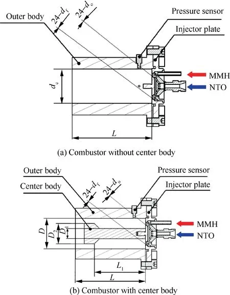
Fig. 1 Schematic of hypergolic propellant combustor.
A schematic of a hypergolic propellant combustor without center body or with center body is shown in Fig. 1. Nitrogen tetroxide (NTO) and monomethylhydrazine (MMH) are oxidizer and fuel,respectively.The injector plate of the combustor possesses 24 like-unlike impinging injector elements. The oxidizer orifice diameter dois 0.39 mm and the fuel orifice diameter dfis 0.31 mm. The angle between the oxidizer orifice and the injector face is 51° and the angle between fuel orifices and the injector face is 53°. Two piezoresistive sensors were mounted with the oxidizer and fuel manifold walls, respectively. The mass flow coefficients of the oxidizer manifold and fuel manifold were calibrated using real propellants before hot fire tests. In hot fire tests, mass flow rates were calculated on basis of the mass flow coefficients and injection pressure drops. The axial distance from impingement points to the injector face is 2 mm and the radial distance from the impingement points to the central axis is 20 mm.The inter diameter of the outer body D is 60 mm and its length L is 140 mm.A center body could be fixed on the injector plate to form an annular chamber with the outer body together or only the outer body forms a cylindrical chamber without a center body. One end diameter of the center body near injector plate D1=26 mm is smaller than the other of the center body near the chamber outlet D2=48.6 mm in order to form a throat. The axial distance L1from the injector face to the throat is 100 mm.Detailed dimensions of the three center bodies are shown in Table 1. A piezoresistive sensor and two piezoelectric sensors were mounted at the side wall of the outer body for monitoring the static and high-frequency pressure,respectively.The piezoelectric sensors were mounted in a small recess of 3 mm to provide protection from hot gases. The axial distance from the sensors to the injector plate was 20 mm. The azimuthal angle difference between two piezoelectric sensorsandwas 90°, as shown in Fig.3. The sample rates of the data collector are up to 102.4 kHz. The two piezoelectric sensors have the same order of effectively responsive frequency with pressure measured in the range of 0-5 MPa and measuring error of 0.15%.Three piezoresistive sensors mounted with the side wall of the chamber are capable of effectively responsive frequency up to 200 Hz with pressure measuring error of 0.5%. The piezoresistive sensor mounted with the side wall of the chamber is in the range of 0-2 MPa and the two piezoresistive sensors mounted with the supply manifolds are in the range of 0-6 MPa. A TTL falling edge signal generated by a DG535(Delay/Pulse Generator) was used to synchronize the pressure signals with the high-speed image records.
As shown in Fig.2,images of OH*chemiluminescence were acquired using a high-speed camera (Phantom v12.1) and UV intensifier (HiCATT25 with hybrid gen2 imager intensifier).The images were acquired using a 45 mm lens (f/1.8) and band-pass filter (310±20 nm). The spatial resolution of the images was approximately 0.285 mm/pixel. The images were collected with an intensifier gate time of 0.9 μs at a sample frequency of 67066 Hz. Photographic settings were all the same for every case,so that OH*chemiluminescence intensity in different cases could be compared with.Images were recorded for about 1.5 s resulting in 100000 images for each operating condition. The spatial and temporal resolutions are sufficient to minimize blurring effects (less than 2 mm) associated with imaging of the acoustic azimuthal combustion instabilities.The position relation between OH*chemiluminescence images and piezoelectric sensors is shown in Fig. 3.
2.2. Operating conditions
A total of 9 combustion cases were conducted in this study,as shown in Table 1. The duration of a typical experiment is about 1.0 s in every case except building pressure and blowdown time. Three piezoresistive sensors measured the static chamber pressure Pcand injection pressures. Pclisted in Table 1 is gage pressure.The pressure drop between the chamber and the oxidizer/fuel manifold was used to calculate theoxidizer/fuel mass flow rate.f is the oscillation frequency in the unstable cases. Stoand Stfare Strouhal numbers of the oxidizer and fuel injectors based on experimental data, respectively. According to Hewitt empirical correlation,25operating conditions of all unstable cases fall into the instability region(f1td/Uj<0.1, where d is oxidizer or fuel orifice diameter, Ujis oxidizer or fuel jet velocity, and f1tis the predictable firstorder azimuthal acoustic frequency of the combustor). Highamplitude instabilities were spontaneously excited in 7 of the 9 tests reviewed.There are two kinds of combustion instability modes listed in Table 1. The first is the first-order spinning mode including Case1-2, Case1-3, Case1-4 and Case1-5. The chamber pressure oscillationsfor spinning modes are mean value of mean-t o-peak pressure oscillations from the piezoelectric sensorsandThe second is the first-order standing mode including Case2-2, Case2-3 and Case2-4. The c hamber pressure oscillationsfor standing modes are mean-to-peak pressure oscillations at the pressure antinode(Choosingordepends on the location of pressure antinode).

Table 1 Test summary conditions and results.
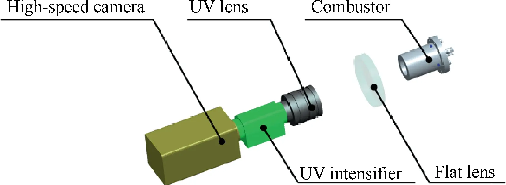
Fig. 2 Schematic of OH* chemiluminescence imaging setup.
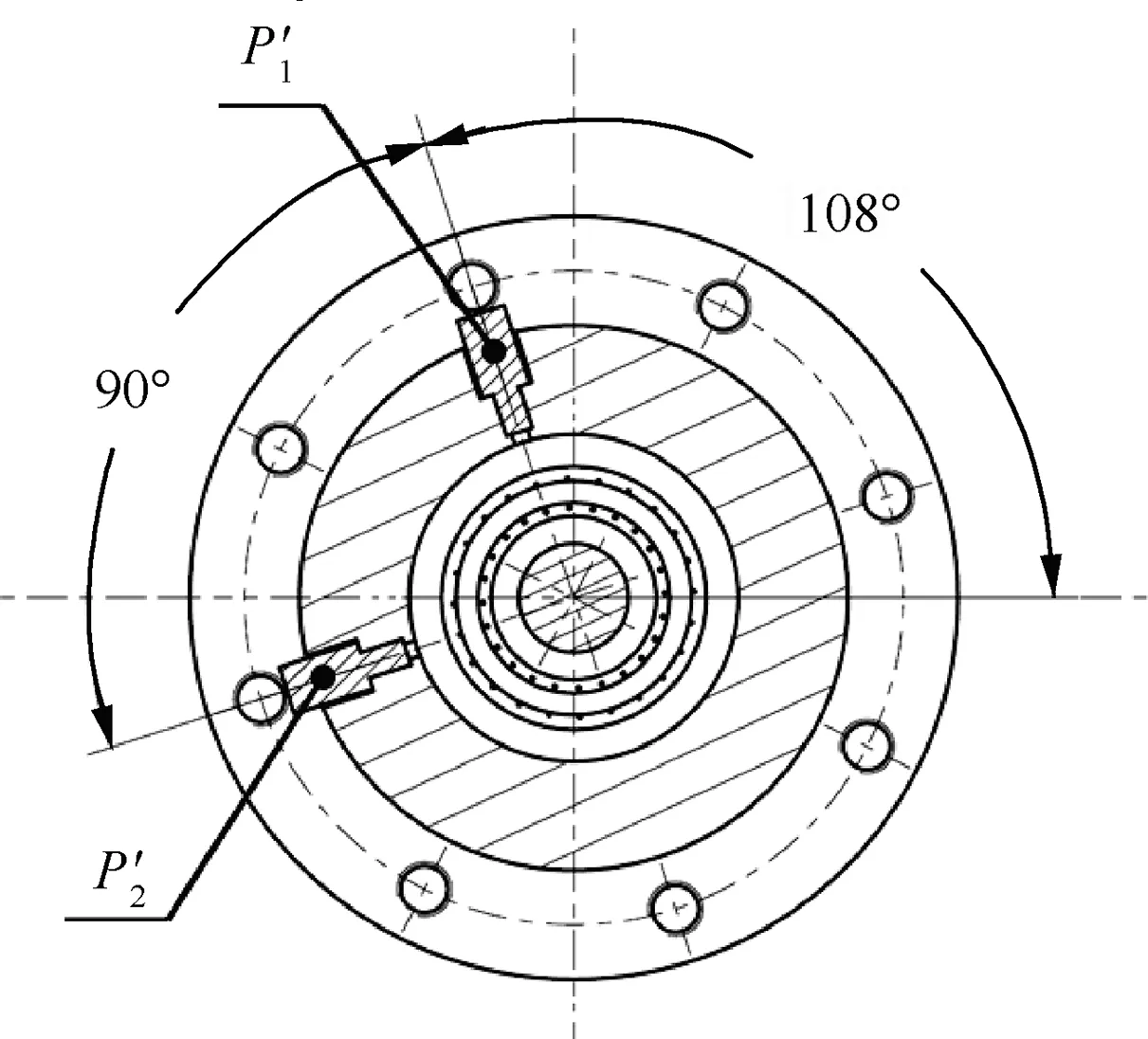
Fig. 3 Schematic of photograph view illustrating piezoelectric sensor locations.
2.3. Analysis methodology of OH* chemiluminescence images
The combustion response could presumably be determined from time-and space-resolved measurements of OH*chemiluminescence emission due to combustion. In order to obtain time-resolved spatial distribution of heat release rate, the grayscale intensity of OH*chemiluminescence images was calculated by using an in-house code of image processing based on Matlab. In this paper, grayscale intensity of images ranges from 0 to 1. First of all, polar coordinates are introduced to define OH* chemiluminescence distribution g(r,θ,kΔt), where r is the radial distance from the geometric center of the combustor, θ is the azimuthal angle, Δt is a time interval of two temporally adjacent images, and k is the sequence number of images. There are two configurations to grid OH* chemiluminescence images.As shown in Fig.4,a series of annular interrogation windows were set up with Rifrom 1 mm to 30 mm and a radial interval ΔR of 1 mm.The radial OH*chemiluminescence distribution with time is expressed as
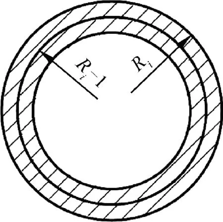
Fig. 4 Schematic of annular interrogation windows.
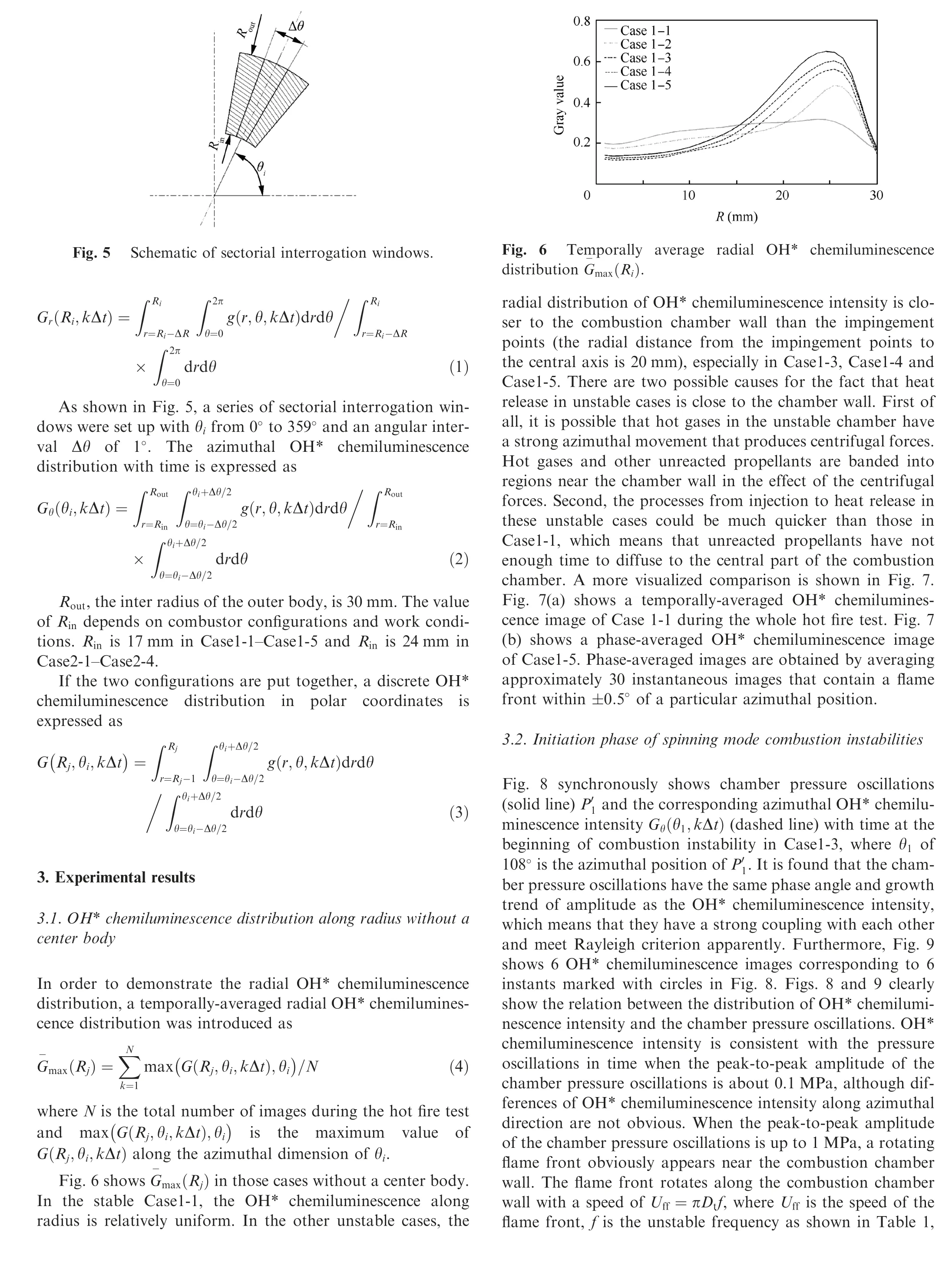
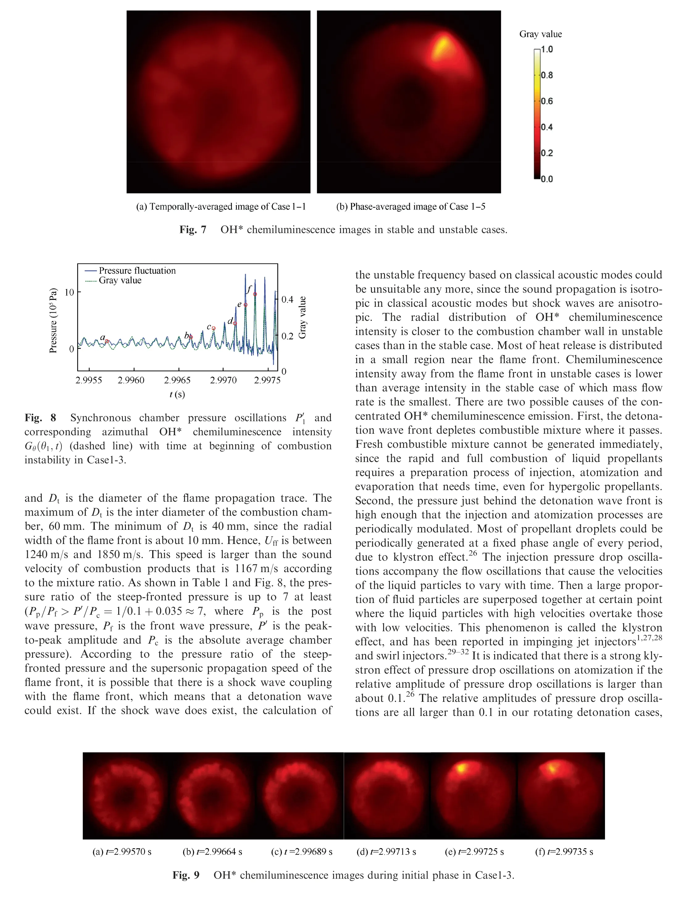
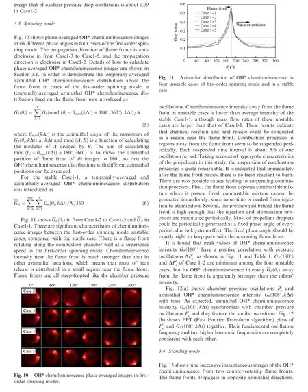
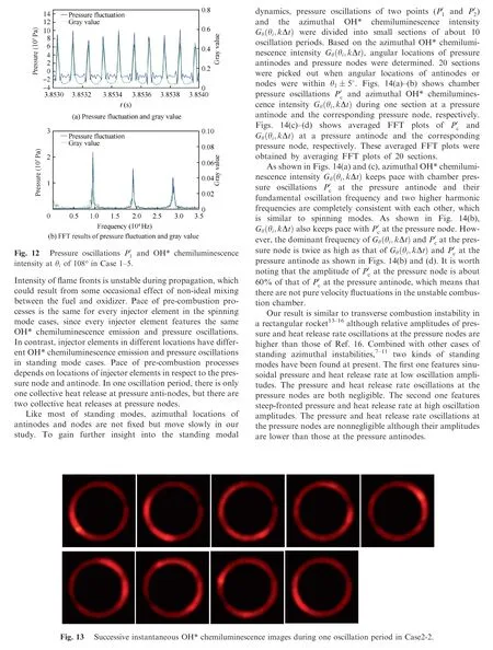
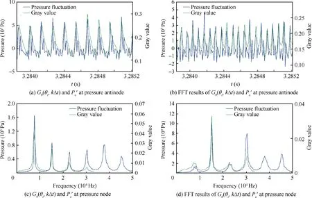
Fig. 14 Pressure oscillations and OH* chemiluminescence intensity Gθ(θi,kΔt) at pressure antinode and corresponding node in Case2-2.
4. Conclusions
The current paper describes an experimental investigation into the modal dynamics of self-excited azimuthal instabilities in an NTO/MMH impinging combustion chamber.9 cases including two combustion chamber configurations were conducted.
The first-order spinning mode combustion instabilities occurred in the cylindrical chamber without a center body.The chamber pressure oscillations keep pace with the corresponding local OH* chemiluminescence intensity in terms of phase angle and oscillation amplitude in the entire initiation phase. However, combustion patterns have a great transformation with huge increase of the chamber pressure oscillation amplitude. A flame front takes shape and rotates along the combustion chamber wall at a supersonic speed until a limitcycle is reached.The radial distribution of OH*chemiluminescence intensity is close to the combustion chamber wall in unstable cases. Most of heat release is distributed in a small region near the flame front.Chemiluminescence intensity away from the flame front in unstable cases is lower than average intensity in the stable case of which mass flow rate is smaller than these unstable cases.
The standing mode combustion instabilities are prone to occur in the annular combustion chamber with a center body.Azimuthal OH* chemiluminescence intensity totally keeps pace with chamber pressure oscillationsat both the pressure antinode and the pressure node. The dominant frequency of Gθθi,kΔt( )andat the pressure node is twice as high as that of Gθ(θi,kΔt) andat the pressure antinode.and Gθθi,kΔt( )at the pressure node cannot be neglected,since their amplitude are both approximately 60% of those at the pressure antinode.The results show that chamber pressure oscillationskeep pace with the corresponding OH*chemiluminescence intensity over the whole combustor no matter in the spinning mode or in the standing mode.It is indicated that the Rayleigh criterion is valid over the whole combustion area in our unstable cases.
Acknowledgements
This work was co-supported by the National Natural Science Foundation of China (Nos. 11502186 and 51506157) and the National Key Basic Research Program of China.
 CHINESE JOURNAL OF AERONAUTICS2020年5期
- CHINESE JOURNAL OF AERONAUTICS的其它文章
- Three-line structured light vision system for non-cooperative satellites in proximity operations
- Remaining useful life prediction of aircraft lithium-ion batteries based on F-distribution particle filter and kernel smoothing algorithm
- Flow characteristics around airfoils near transonic buffet onset conditions
- Experimental investigation of flow and distortion mitigation by mechanical vortex generators in a coupled serpentine inlet-turbofan engine system
- An improved prediction model for corner stall in axial compressors with dihedral effect
- Consensus disturbance rejection control of directed multi-agent networks with extended state observer
