Three-line structured light vision system for non-cooperative satellites in proximity operations
Yang LIU, Zongwu XIE, Hong LIU
State Key Laboratory of Robotics and System, Harbin Institute of Technology, Harbin 150000, China
KEYWORDS Adapter ring;Line detection;Non-cooperative target;Pose measurement;Space robot;Structured light
Abstract Adapter ring is a commonly used component in non-cooperative satellites, which has high strength and is suitable to be recognized and grasped by the space manipulator.During proximity operations,this circle feature may be occluded by the robot arm or limited field of view.Moreover,the captured images may be underexposed when there is not enough illumination.To address these problems, this paper presents a structured light vision system with three line lasers and a monocular camera. The lasers project lines onto the surface of the satellite, and six break points are formed along both sides of the adapter ring. A closed-form solution for real-time pose estimation is given using these break points.Then,a virtual structured light platform is constructed to simulate synthetic images of the target satellite.Compared with the predefined camera parameters and relative positions, the proposed method is demonstrated to be more effective, especially at a close distance.Besides,a physical space verification system is set up to prove the effectiveness and robustness of our method under different light conditions. Experimental results indicate that it is a practical and effective method for the pose measurement of on-orbit tasks.
1. Introduction
On-Orbit Servicing (OOS) is expected to play an important role in future space activities.1The goal of OOS missions is to prolong the lifetime of the target spacecraft,which is usually influenced by the limited propellant and the degradation of hardware components.2Apart from repair and life-extension,it also provides an effective solution to decrease the space debris by de-orbiting abandoned satellites. One broad area of application is in the service construction, and maintenance of satellites and large space structures in orbit.3
It is reported by the Union of Concerned Scientists (UCS)that, until the end of 2016, 493 out of 1381 satellites had executed their mission in Geostationary Equatorial Orbit(GEO).4Frequent failures of GEO satellites result in large economic cost and other bad consequences.5Besides, the increasing number of GEO debris makes the orbit more and more crowded, leading to a high possibility of collisions. A number of studies have demonstrated potential savings in terms of the cost-effectiveness of OOS on the damaged spacecraft.6Therefore,many countries and organizations have researched on the OOS technologies, including repairing, upgrading, refueling and re-orbiting spacecraft on orbit. Experimental demonstrations include but not limited to: ETS-VII,7FREND8and RSGS.9
All the above-mentioned applications justify the development of safe and efficient strategies during the capturing phase.How to conduct completely unmanned and fully autonomous on-orbit missions has become the focus of concern. For this reason, the capturing and docking technologies have developed into the essential prerequisites of on-orbit servicing.10
However, most of the on-orbit satellites are noncooperative, i.e. there is no specially designed mechanism mounted on these satellites for capturing. Therefore, we have to rely on the natural features from the target satellite.Among the common features of the mechanical design on conventional satellites,the adapter ring is a good candidate to be grasped.It is a high-strength torus with a radius of 1194 mm or 1666 mm,8,11which is utilized to connect the satellite to the launch vehicle.
Recently, more attentions have been focused on the closed-loop maneuvering,12especially for missions that involve automated rendezvous, docking, and proximity operations. Thus, the real-time pose measurement of the target has been identified as a key development area for future space programs,13which can improve the robustness, fuel efficiency, safety, and reliability of OSS through the visual feedback control. At present, many institutes have carried out studies on the pose measurement of non-cooperative satellite based on the adapter ring. With the circular feature,the relative position can be resolved while two solutions of the orientation are obtained.14Zhang et al.15used a laser rangefinder to select the correct result as the laser point and the circular feature were on the same plane. However,the projection point may come from the base of the satellite rather than the adapter ring. Similarly, line structured light16can also be used to eliminate the ambiguity and calculate the circular radius as well as the pose information. Instead of using additional sensors, Du et al.17made use of the vanishing points to solve the orientation-duality problem.Nevertheless, the result was related to a known diameter as prior information. Miao and Zhu18proposed a new method to remove the false solution by using the Euclidean distance invariance. However, it was hard to find a fixed point, especially in close view. Xu et al.19improved this method by using a stereo camera system, but the effective field angle is smaller than the monocular vision system.
Those methods all depend on the projection ellipse from the adapter ring. During proximity operations, the tracking feature may not be captured due to the limited field of view20.Furthermore, the target may be obstructed by a robotic arm or related end-effectors21, leading to the occlusion problem.Moreover,it is difficult to track the adapter ring when the target is tumbling in bad illumination condition22. In this case,the hand-eye camera can only obtain partial circular feature23and the tracking accuracy decreases as well.
To address these problems, active vision technologies such as the line structured light have been introduced.Based on the projection measurement, the detection result is highly precise,rapid, and robust24. When the outer surface changes, the projection line on the image also performs different displacement25. Based on the partial rectangular framework, Gao et al.26presented a structured light system that was suitable for large non-cooperative satellites. Yang et al.23established a double-line structured light vision measurement model.Using the break points between the light planes and partial docking ring, the pose information could be uniquely determined.As the center point was computed using the perpendicular bisectors, the detection accuracy would largely decrease when the structured light planes were close in distance with each other.
In this paper, a structured light vision system is proposed to estimate the pose of the non-cooperative satellites, which is comprised of a monocular camera and three laser projectors. These projectors are used to emit lines on the surface of the satellite, and six break points will then appear along the inner/outer edges of the adapter ring. Relative pose information is solved using the least square method instead of traditional geometric intersections. It has been tested both on the virtual simulation platform and the ground experiment system. Experimental results indicate that it is able to cope with problems like critical illumination, limited field of view and occlusions. Besides, it also reduces the motion blur of the tumbling target and enhances depth perception by focusing on these break points other than the whole image.
The rest of the paper is organized as follows: Section 2 introduces the pose measurement model and briefly explains the relationship between the structured light plane and the camera. Section 3 proposes a length-based line segment detector, which fits lines due to the length condition rather than least squares errors. Without continuous linear fitting, this detector can save the execution time and memory, making it suitable for the on-board computer system.Section 4 discusses the calibration process of the light plane. A planar calibration board made up of ArUco markers is introduced to establish the mapping relationship between the light plane and camera coordinates. Section 5 gives the closed-form solution for pose estimation. The position of the target satellite is described by the center of the adapter ring, and its orientation is expressed by the pitch and yaw angles.Section 6 comments on the experimental results both on synthetic and real images over different light conditions and distance. Conclusions are drawn in Section 7.
2. Pose measurement model
Some organizations and scholars have studied the issues about on-orbit servicing of non-cooperative satellites and a few methods for pose determination have been proposed. As the accuracy of camera type sensor is usually a function of relative position, it is more stringent in close-proximity operations,especially in the capturing phase.
As illustrated in Fig.1,a line structured light vision system that composed of three line laser projectors and a monocular camera is presented to determine the pose of the target satellite.These laser projectors are arranged in a line,and the pitch angles are adjusted slightly to form three parallel lines and the corresponding light planes Sl,Smand Sr.This system is able to obtain the depth information when the camera captures the laser light stripes on an object illuminated by the projector.Moreover, the pinhole model is introduced to define the geometric relationship between a 3D point and its 2D corresponding projection on the image plane, and the linear structured light projector is modelled by the space plane.
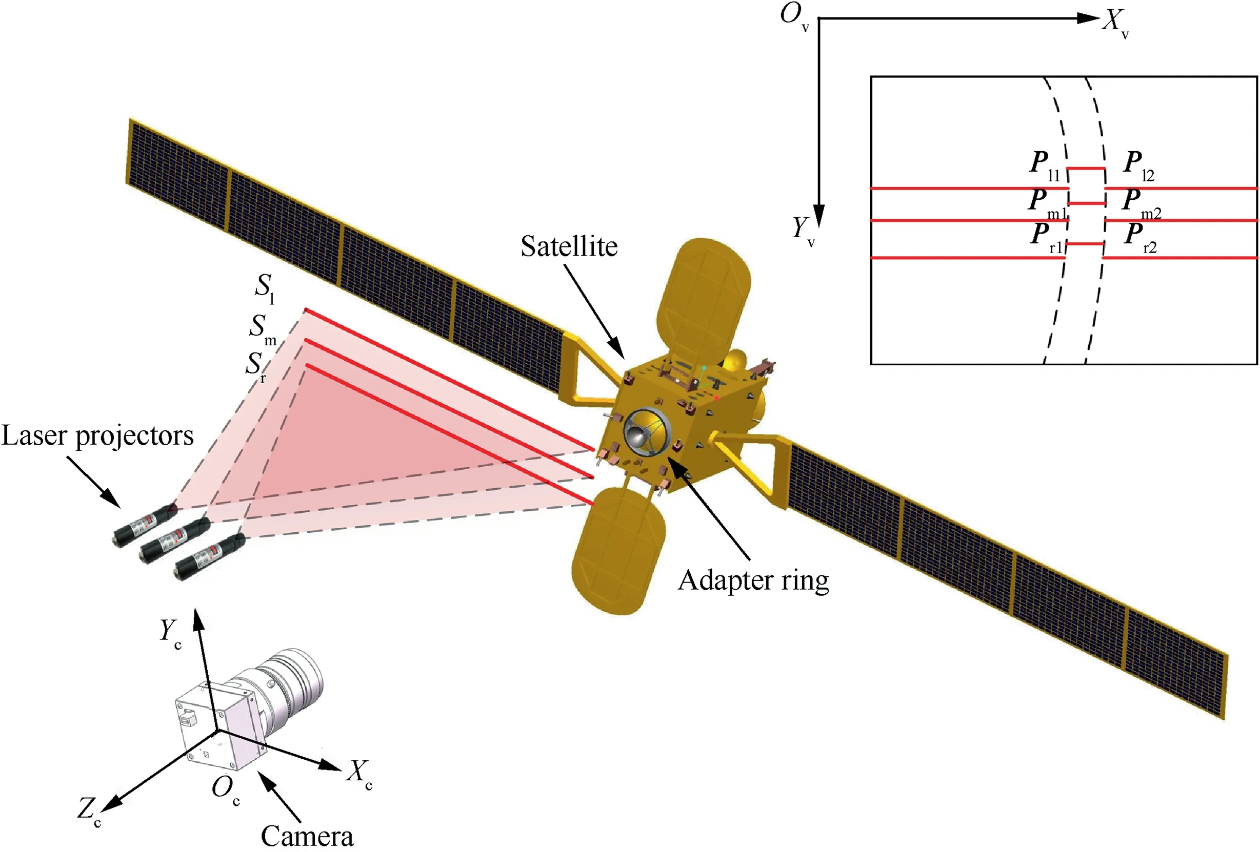
Fig. 1 Three-line structured light measurement model.
2.1. Camera model
The pinhole camera model describes the mathematical relationship between a point in 3D space and its 2D projection on the image plane with the intrinsic and extrinsic parameters.These parameters not only demonstrate the optical properties but also describe the position and orientation of the camera.
As shown in Eq.(1),the intrinsic matrix Mf(without distortion) describes the relationship between the camera coordinates and the pixel coordinates. It is made up of the focal length fx/fyand the principal point (cx, cy). All these parameters can be determined by the camera calibration.

The extrinsic matrix represents the position and orientation of the camera relative to a given reference coordinate system such as the world coordinates.In this paper,we set the camera coordinate system as the reference frame. Therefore, the extrinsic matrix turns to be a 4×4 identity matrix.
2.2. Linear structured light projector model
The laser projectors are fixed above the camera and emit parallel line structured lights towards the target. The light plane can be expressed by the following equation:

where the normal vector of this plane can be represented as n=[a,b,c]T.Since the line plane is located above the camera,d is nonzero constant. Each light plane intersects with the target and leads to a pair of break points on the adapter ring.Using these points Pi1and Pi2(i=l,m or r),the pose information of the adapter ring can be determined according to the linear structured-light vision principle.
3. Line detection method
In this section, line detection method is introduced to extract those break points illustrated in Fig. 1. Traditional line detection methods like Hough Transform(HT)27and the improved algorithms28,29suffer from some inherent limitations such as long computation time and large memory requirements, making them unsuitable for the on-board computer system.
A length-based line segment detector is proposed based on the length condition rather than least squares errors. It approximates lines under the assumption that the curve satisfies some straightness criterions. On the one hand, it can reduce the number of edge points while keeping the desired accuracy; on the other hand, it avoids the calculation of the linear equations.
3.1. Edge segment detection
For higher efficiency,most of the line segment detectors adopt an edge detection scheme to get the binary edge map at first,which significantly reduces the amount of data and preserves the structural properties for further image processing. Thus,a fast and robust edge detector is proposed to extract edge segments in this paper.
Anchors are the peaks on the gradient map where the edges will probably put over,and they are of great importance in the applications such as object detection. In contrast with the neighbor points along its gradient direction, all the anchors can be simply distinguished and extracted. It should be noted that an anchor is just a possible location where one edge segment starts,and not all the anchors will be retained in the final edge map.
Then,a double threshold algorithm is applied to determine the potential edge pixels. Points whose gradient magnitude is less than the upper threshold will be removed from the anchor list,and the lower threshold is used to delete pixels with smaller values in the gradient map.
After that, a property named segment direction is introduced,which represents the trajectory of one segment.The definition is different from the gradient direction as it is related to the connection of the neighbor pixel. For example, if the next maximum gradient point is on the left of the current one, its direction is left.Based on the hypothesis that an edge segment always has continuous curvature until to the sharp corners,we assume the segment direction of the current point is equal to the former one and check the next point along this direction as well as two linked neighbor points. Pixel with the largest gradient value is regarded as the next edge point, and the segment direction can be figured out as well.
In descending order of the gradient, we start two edge segments with opposite directions from each anchor point. Each segment stretches until it moves out of the edge areas. These two short segments will be connected at the start point if it is longer than the length threshold. The detection result is a collection of edge segments, each of which is a clean, continuous, 1-pixel wide chain of pixels.
3.2. Length condition
Instead of using the least squares fitting method,length condition is considered here to approximate the edge segments in a way that the curve satisfies a criterion of approximation quality. For an arbitrary edge segment, the segment direction of each point has been defined in the edge detection step. These edge points can be classified into three groups: horizontal(left and right), vertical (up and down) and oblique (up-right,down-right, down-left and up-left). Three parameters are then defined to count the numbers of edge points in each group:nh,nvand no.The physical meaning of these parameters is related to the projection distance onto different directions. For an arbitrary edge segment, nhrepresents the width between the start and end points along the x axis, and nvrepresents the height information along the y axis. Besides, noindicates that the edge projection holds nopixels on both axes.Table 1 illustrates some short segments with the last point marked in gray.
Type

Table 1 Five short edge segments with directions counted.
According to the Pythagorean Theorem, the estimated length (distance between the centers of the start and end points) is:

In addition,we can also use the Euler distance to represent the length of the current segment:

As illustrated by Fig. 2(a), the estimated length is equal to the ground truth when it is a straight line.The more it departs from the straight line,the larger Dris,while the Euler distance Ddis in the opposite situation.As a result,the length deviation increases with the edge curvature, which means we can regard one segment as a straight line when the deviation is shorter than a threshold.
3.3. False detection
For arbitrary edge segment, the length deviation is checked pixel by pixel from the start point. When it exceeds the deviation threshold,the edge segment will be split and the past pixels are regarded as a line segment.
However,this assumption is not always true.Sometimes the detected result is far from a straight line even if the deviation equals to zero. As shown in Table 2, the length condition demonstrates that both segments are straight lines. Nevertheless, the upper one is a wrong detection which should be split at the corner while the lower is possibly true from a slope. To eliminate the wrong detections,the distribution of the segment directions is also taken into consideration.
The initial direction proportions are computed by the first l0points, and the length deviation as well as the direction distribution is analyzed pixel by pixel. The line detection method can be regarded as a consecutive linear fitting progress thatholds the outline information while cutting down the redundant points. It neither needs to fit lines through the least squares method, nor cares about the gradients. Thus, the execution time is far less than traditional methods.

Table 2 False detection based on length condition.
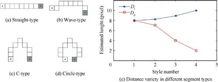
Fig. 2 Deviation tendency over different edge segments.
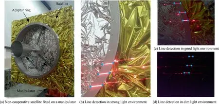
Fig. 3 Line detection results (marked with blue endpoints) in different environments.
The proposed line detector has been tested in different light conditions as shown in Fig.3.The satellite model is covered by a sheet called MultiLayer Insulation (MLI) as in the outer space,which helps insulate against thermal losses such as heat conduction or convection.This covered sheet is usually a 0.001 inch (1 inch=0.0254 m) Kapton film backed with a few angstroms thick layer of silver, leading to the gold color and a strong reflection. Hence, the detection result is easily overexposed and suffers from a cluttered background when the light is intense.This situation can be improved in the dim light environment,which differs from the traditional detection methods.For better observation, our results are marked with blue dots corresponding to the break points in Fig. 1.determines its identifier (id). The black border facilitates the detection efficiency from the source image, and the binary codification allows its identification, error detection and correction techniques.Its detection pipeline is much more effective and faster than the other similar Augmented Reality (AR) tags, especially in the indoor environments.30Therefore, it is widely used in various applications such as robotics and augmented reality.
The marker detection process is performed in two main steps: the detection of marker candidates and codification analysis. The former focuses on the extraction of candidate shapes, and the latter analyzes the inner codification to determine whether the marker belongs to a specific tag dictionary.Given the marker size and calibration parameters of the camera, the pose information relative to the camera can be identified directly.
It can be observed from Fig. 4 that the calibration board contains four ArUco markers located at each corner. The
4. Two-step calibration for light plane estimation
In this section, a two-step calibration method is proposed to establish the mapping relationship between the light plane and camera coordinates.First,a planar calibration board consisting of four ArUco markers is designed. Then, we put this board in front of the camera and ensure that all the light stripes have passed through its surface.The monocular camera captures the image of the calibration board, and the equation of the top plane can be figured out based on the ArUco markers. Besides, all the 3D coordinates of the points on the light stripes can be solved accordingly. Moreover, the equation of the structured light plane (Sl, Smand Sr) with respect to the camera coordinate system can also be estimated using the least squares method.
4.1. Design and calibration of ArUco board
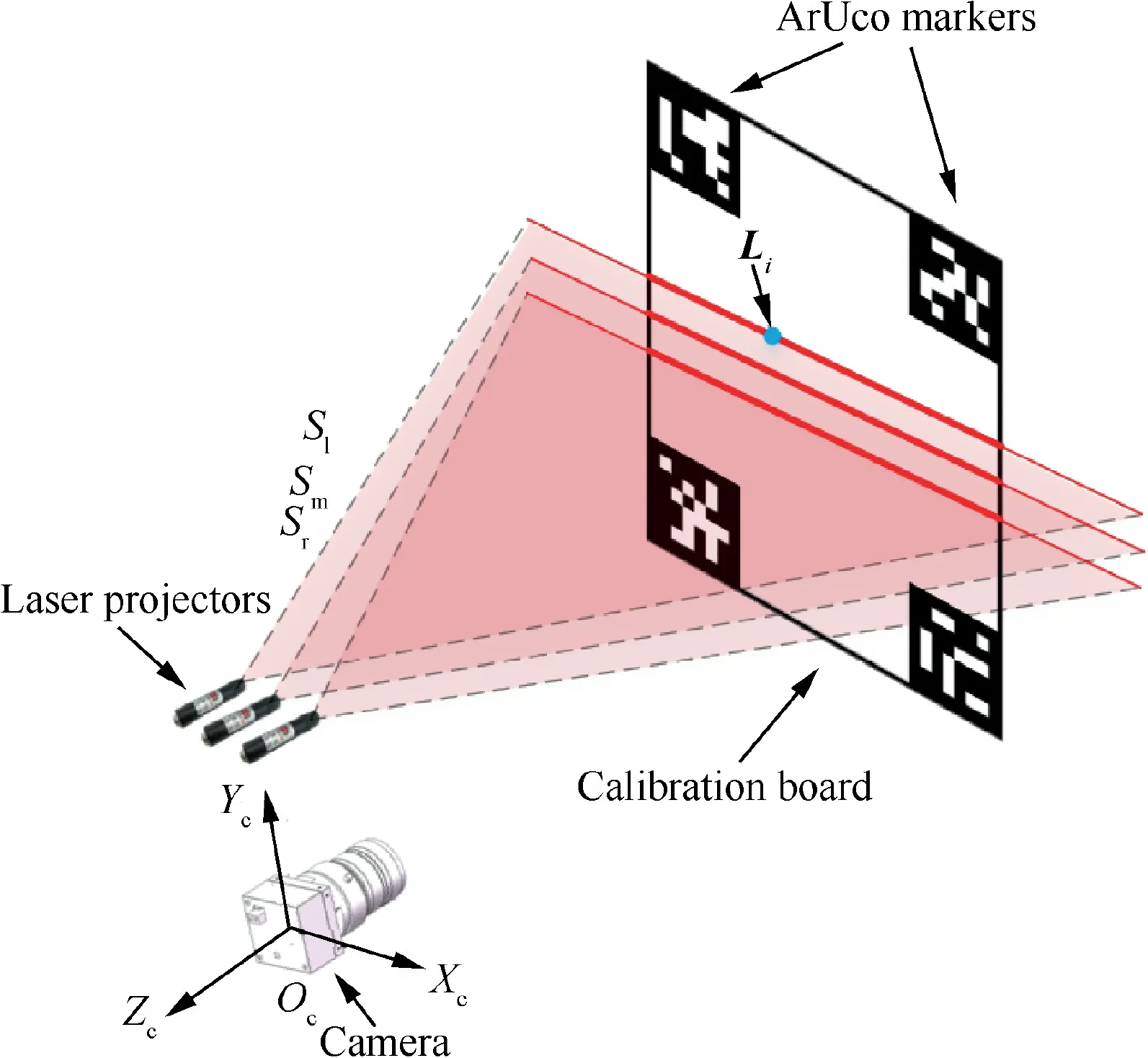
Fig. 4 Calibration board made up of four ArUco markers.
ArUco marker is a synthetic square marker composed of a wide black border and an inner binary matrix which structured light planes intersect with this designed board, and three parallel light stripes are formed straightly. As there is a clean, white background on the calibration board, the 2D coordinates of these points on the light stripes can be easily figured out.
For OpenCV 3 and above, the ArUco modules are part of the extra contributed functionality. By applying the estimatePoseSingleMarkers function to each of the markers, a rotation vector (described in Rodrigues’ rotation formula)and a translation vector can be obtained. These two vectors describe the transformation of each marker coordinate system with respect to the camera frame. The marker coordinate system is located on the center of the marker,with the z axis perpendicular to the marker plane.
The translation vector[xic,yic,zic]Trepresents the origin of the marker coordinate system expressed in the camera frame.Hence, the center point of this calibration board can be represented as [xcc, ycc, zcc]Tby taking average of those four vectors. Similarly, the normal vector of this board[ncx, ncy, ncz]Tcan be solved using the above Rodrigues parameters. Finally, the plane equation of the calibration board can be expressed as:
4.2. Calibration of light plane
According to Eq. (1), the intrinsic matrix represents a projective transformation from the 3D camera coordinates to the 2D image plane. Given an arbitrary point Lion the light stripes, its x coordinate in the camera frame as well as the y coordinate is related to the distance along the z axis, which can be described as:

where[xic,yic,zic]Tis the coordinate of Liin the camera frame and [xiv, yiv]Trepresents the corresponding coordinates on the image plane. With the proposed line edge detector, the image coordinates of Liare easily picked up. Considering that the focal length and principal point are known parameters, the explicit formula of Liis then derived.
Besides, Liis also on the calibration board. Substituting Eq. (6) into Eq. (5), the following equations can be obtained:

Then, the unique position of Liwith respect to the camera coordinate system can be found. Moreover, the structured light plane can also be given by:

where S=[sx, sy, sz]Trepresents the normal vector of each light plane. Among these coefficients, syhas the largest absolute value, and the sign of syis opposite to sd. Suppose that there are n points on the current light stripe, we then get the following linear equations in matrix form:

Similar to the line equations in 3D space,it should be noted that the equation for a given plane and the corresponding normal vector are not unique.Thus,sdis set to be 1 in this paper,which scales the normal vector while keeping the orientation.In this case,the specific solution of the above linear equations can be calculated through the method of least squares,and the normal vector S can be described as:

5. Pose measurement of adapter ring
When the object moves in front of the camera, the projection line stripe also changes on the reflected image. Since all the light planes have been calibrated in the previous section, the pose information of the target can be measured using the structured light vision system.
In this section,those break points Pi1and Pi2(i=l,m or r)in Fig.1 are picked up to estimate the position and orientation of the target satellite. On the one hand, they are easily extracted from the image; on the other hand, it helps speed up the execution time by focusing on the scattered points rather than the whole line.
5.1. Acquisition of break points
By applying the proposed line edge detector in Section 3, the pixel coordinates of the break points can be figured out in turns. These points are not only on the structured light plane but also meet the camera projection principle. Thus, we can combine Eqs. (6) and (8) as

Therefore, the 3D coordinates of Piin the camera coordinate system are represented as

5.2. Pose estimation
Taking an average of those break points, we can get the candidate grasping location for the robotic arm or related end-effectors. Besides, the orientation of the target satellite also plays an important role in OOS operations such as path planning. In this case, all the pose information needs to be solved. After that, the current position of the on-board equipment can be estimated through the installation matrix or joint angles.
By modelling the adapter ring as a planar circular feature,the pose parameters of the target satellite can be described by the coordinates of the circle center and the normal vector of the circular plane with respect to the camera frame. Note that the circular feature keeps invariant no matter how much it rotates around the normal vector,so there are only two attitude degrees of freedom in orientation. However, it is enough to realize the tracking and grasping of the non-cooperative satellites just by using three position degrees of freedom and two attitude degrees of freedom.In this paper,the Zbaxis perpendicular to the adapter ring describes the orientation of the satellite.The Xbaxis is fixed along with the solar array,and the Ybaxis is denoted by the right-hand rule.
Suppose that nxx+nyy+nzz=1 is the plane equation where the adapter ring lies on, the normal vector of this plane can be represented as Zb=[nx,ny,nz]T.As all the break points come from the adapter ring, the following equations can be obtained:


This redundant equation can also be solved by the least squares method, and the normal vector is given by:In addition,the pitch angle θ is defined as the angle between the Xc-Zcplane and the normal vector.The angle between the projection of the normal vector on the Xc-Zcplane and the Zcaxis is defined as yaw angle φ. The relationship between the normal vector and the Roll Pitch Yaw (RPY) angles can be then expressed as:

In the camera coordinate system, the center of the adapter ring is represented by R=[rcx, rcy, rcz]T. And ri/rostands for the inner/outer radius, respectively. As the distance between the edge point and circle center keeps equivalent along either side of the ring, we then have the following equations:

By subtracting the first equation from the second one in Eq. (16), the following equation is derived:

where Almand Mlmare known parameters calculated from the 3D coordinates of Pl1and Pm1.Combining the distance equivalently about ri/rowith the plane equation,we then get the following matrix equation:
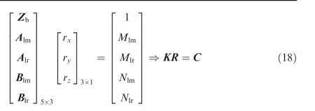
where Alm/Alris derived from the equivalence of the inner radius,and Blm/Blris derived from the equivalence of the outer one.Besides,the parameters Mlm,Mlr,Nlmand Nlrare related to the break points, and the center of the adapter ring can be given by:

Until now, the relative position and orientation have been determined. The position of the target satellite with respect to the camera frame is characterized by R, and its orientation is expressed by the pitch angle θ and the yaw angle φ.Furthermore,the radius of the adapter ring can also be determined by averaging the distance between the circle center and those break points.
6. Experimental results
To verify the effectiveness and robustness of the proposed method, we first tested our algorithm on 150 synthetic images with several distances.As the sunlight in outer space is intense and highly directional,real images under different light conditions were used to evaluate the detection stability. All the following algorithms are implemented on a PC (I3-3240 at 3.4 GHz, 8 GB of RAM) with Win10.
6.1. Simulation results
OpenGL is a cross-platform Application Programming Interface (API) for rendering 2D and 3D vector graphics and provides various libraries and functions for 3D software development. Thus, OpenGL is widely used in visually compelling graphics software applications, CAD, information visualization and virtual reality.
Based on OpenGL, a real-time virtual simulation platform is built to get the synthetic images of the satellites.It adopts the computer-graphics technology and has the advantages of cheap costs, reliable technology, flexibility and convenience.31The projection model is established based on the Sinosat-2 satellite, a failure satellite of China.
As shown in Fig.5,the platform loads the 3D model of the satellite and demonstrates the on-orbit environment using two cameras: global camera and monocular camera. The additional global camera is used to show the position of the virtual structured light system. The position of the global camera can be adjusted for more details using the computer mouse: rotating, moving or scaling. Besides, camera parameters as well as the relative positions can be changed through the control console. Given a pre-computed trajectory, the target satellite can carry out the movement and output the synthetic images using TCP/IP.
Using the central perspective imaging model, the intrinsic camera parameters can be estimated directly through the selected parameters:
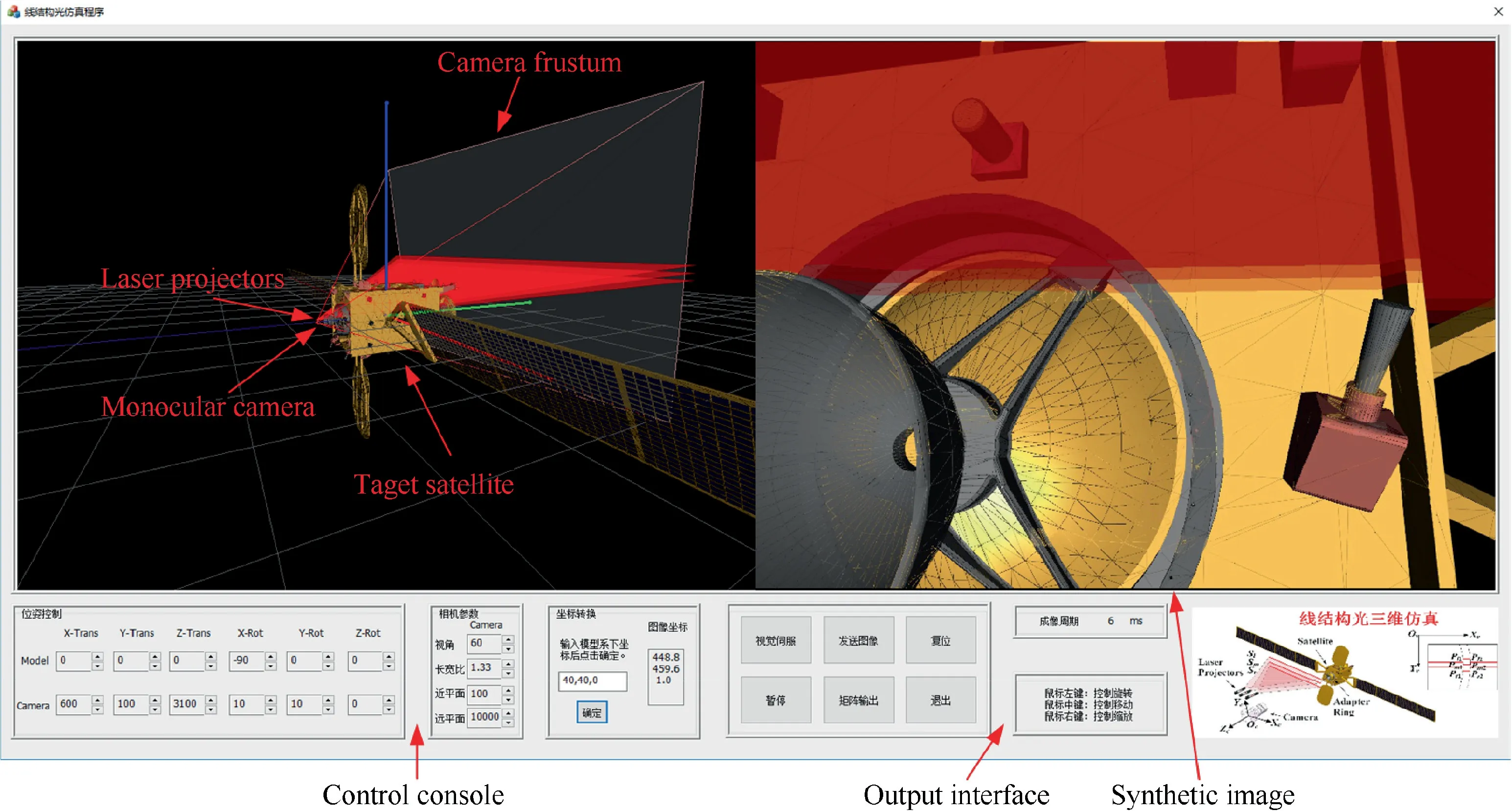
Fig. 5 Virtual structured light platform.

where W and H are the width and height of the output image,r and l represent the x coordinates of the right and left corners of the near plane respectively. In addition, t and b correspond to the y coordinates of the top and bottom corners of this plane,and n is the distance between the camera center and the near plane.
The laser projectors hold a linear distribution above the camera. The middle projector is parallel to the Xc-Zcplane,and the other two have a slight deviation angle of α. Then,the equations of the structured light plane can be described as:

where cαand sαrepresent the trigonometric values about α,and d is the height distance between the laser projector and the camera. In this section, the deviation angle α equals to 1.5°,and the height distance d is set to be 100 mm.
Using this platform, we can get the synthetic images of the target satellite with accurate positions. Taking the final grasping step as an example,the trajectory of the camera was simulated, and the error analysis was performed along the z axis:200 mm, 500 mm and 1000 mm. For each location, 50 images were captured with various positions. Compared with the given positions, the proposed method is evaluated on these images and the detection result is illustrated in Table 3.
Synthetic images in the first row are simulated at different distances (marked in the upper right corner). The detection accuracy can be found in the rest of Table 3, including the position error and the angle error.As the center of the adapter ring has an indirect correlation with the break points,there is a large error on the detection results.The position error of the z axis is a little larger than that of the other two axes, and the detection accuracy has been improved with the relative distance. Due to the limited field of view, only partial ellipse feature is captured among proximity operations.Thus,traditional pose measurement methods(e.g.,ellipse tracking19)are ineffective since it is difficult to find a stable, desirable and common feature on the target satellite. However, the proposed method can be always implemented as the laser projectors will ensure the appearance of the break points in front of the camera.
As shown in Table 3, the adjacent lights are so close that the inner/outer break points are nearly on the same straight line. As the circle center is on the perpendicular bisectors of the segments Pl1Pm1and Pm1Pr1,the intersection point appearsat an infinite distance.This configuration will also increase the condition number of the matrix K in Eq.(19),which result in a near-singular situation of the least squares solution.

Table 3 Detection results on synthetic images.
6.2. Experiments on ground experiment system
To verify the proposed method, we also tested our algorithm on the ground experiment system as shown in Fig.6.This system mainly consists of the following parts:structured light system, space robot controller, electronic simulator of space robot, dynamics simulation computer, two fixed industrial robots,and so on.The industrial robot A was used to simulate the motion of the chaser satellite,and robot B was employed to simulate the tumbling target satellite with nutation.Guided by the structured light system, the mounted space manipulator was adopted to grasp the adapter ring during proximity operations. The electronic emulator could simulate the interaction state of the real space robot.It was in communication with the space robot controller and dynamics simulation module based on CAN-bus.The dynamics simulation system could figure out the disturbance of the satellite base owing to the motion of the space manipulator. As the space manipulator had a float base rather than a fixed ground, the kinematics equivalent method was used to control the industrial robot as well as the space manipulator.
As shown in Fig.7,the structured light system is comprised of one camera and three laser projectors. Its size is only 100 mm×100 mm×150 mm and can be easily mounted on any robot manipulator without special space request. According to the detection results on synthetic images, the deviation angle α has been increased to 10° to get rid of large condition number.At the singular configuration,the radius increases largely, and the Damped Least-Squares (DLS) method is then introduced to deal with this problem. The middle projector is located 70 mm above the camera,and its center point is 20 mm behind the camera to avoid occlusion. The other two projectors stay 30 mm from the camera on both sides, and the relative height is 40 mm. The middle projector is installed parallel to the camera, and the other two are with +10° and -10°angle deviations respectively. The resolution of the monocular camera is 1600×1200 pixels.The focus length of the camera is 8 mm. More specific parameters can be found in Table 4.
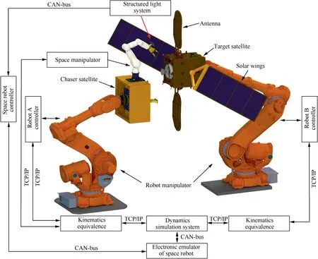
Fig. 6 Overview of space robot verification system on ground.

Fig. 7 Structured light system and captured images in different environment.

Table 4 Configuration details of structured light system.
The proposed method has been tested in various light environments.When the adapter ring gets a direct sunlight,there is a strong reflection due to the covered MLI, leading to a complex background noise. Besides, our method has a superior result in the dim light environment,which means it works well even when the adapter ring is opposite to the sun.
As detailed in Table 5, the accuracy analysis is carried out to verify the performance of our method on real images. On each illumination configuration, the proposed algorithm was executed 100 times with different relative pose between 1000 mm and 200 mm.Increased deviation angle has improved the interval distance as well as the detection accuracy.Besides,the strong light affects the line detection process and decreases the detection accuracy. Moreover, the execution time is also counted in the last row of the table. It can be obtained that the proposed method runs the fastest in dim condition due to the pure background.Pose information in this paper is only related to the six break points,so guarantees the real-time performance. However, the measurement error keeps a high level as the circle center is an indirect variable,especially when those points are close with each other.
According to the detection results on synthetic and real images,we can conclude that the structured light system is able to get the position and orientation of the target satellite during proximity operations. Three laser projectors are employed to display lines in the field of view, and six break points then appear along the inner/outer edges of the ring. Since the pose information in this paper is only related to the six break points,the proposed method can be applied to on-orbit tasks in real time. Our method has a good robustness over different light configurations, and the detection accuracy is related to the deviation angle of the light plane. On the one hand, a largerangle will increase the detection accuracy; on the other hand,the light stripes may move out of the image if the deviation angle is too large. Besides, the proposed method also solves the feature extraction problem as traditional features become partial or even lost in close distance.
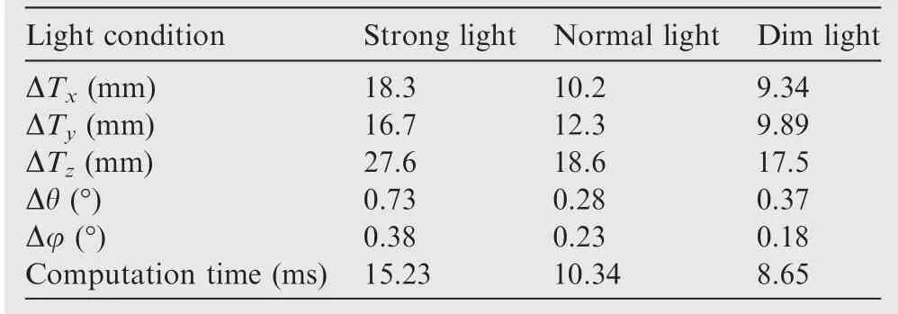
Table 5 Detection results on real images.
7. Conclusions
(1) A structured light vision system is designed for the pose measurement of the non-cooperative satellites during proximity operations. It is composed of three laser projectors and a monocular camera.Using the active vision technology,it can cope with problems like critical illumination, limited field of view and occlusions. Besides, it also reduces the motion blur of the tumbling target and enhances depth perception by focusing on six break points rather than the whole image.
(2) To get those break points, a length-based line segment detector is proposed based on the length condition rather than least squares errors. It approximates the lines in a way that the curve satisfies a criterion of approximation quality, making it suitable for the onboard computer system.
(3) Based on the ArUco markers,a planar calibration board is introduced to establish the mapping relationship between the light plane and camera coordinates.It helps to solve the equations of all the structured light planes using the least squares method. Then, the 3D coordinates of the break points can be figured out.
(4) A real-time virtual structured light platform is built up to simulate synthetic images of the target satellite.Compared with the predefined camera parameters and relative positions, the proposed pose estimation method is demonstrated to be effective,especially in close distance.
(5) Furthermore, a ground experiment system is set up to verify the effectiveness and robustness of the proposed method on different light conditions. Our method describes the target using the center of the adapter ring and the pitch/yaw angle of the satellite in real time.And it has a better detection result in the dim light environment using the laser projectors.
(6) The center point is no longer measured by the geometric intersections.A closed-form solution for pose estimation is given using the least square method. Thus, methods such as pseudoinverse and Damped Least-Squares(DLS) can be used to solve the nearly parallel problem of the perpendicular bisectors.
(7) Compared with other pose measurement methods, our method does not need the value of circular radius and has stronger robustness. It is a practical and effective method for pose measurement of OOS operations and can be easily applied to real-time industrial robotics.
Acknowledgements
The authors would like to acknowledge the financial support provided by the Foundation for Innovative Research Groups of the National Natural Science Foundation of China (Nos.51521003 and 61690210).
 CHINESE JOURNAL OF AERONAUTICS2020年5期
- CHINESE JOURNAL OF AERONAUTICS的其它文章
- Experimental of combustion instability in NTO/MMH impinging combustion chambers
- Remaining useful life prediction of aircraft lithium-ion batteries based on F-distribution particle filter and kernel smoothing algorithm
- Flow characteristics around airfoils near transonic buffet onset conditions
- Experimental investigation of flow and distortion mitigation by mechanical vortex generators in a coupled serpentine inlet-turbofan engine system
- An improved prediction model for corner stall in axial compressors with dihedral effect
- Consensus disturbance rejection control of directed multi-agent networks with extended state observer
