Microstructure, thermophysical property and ablation behavior of high thermal conductivity carbon/carbon composites after heat-treatment
Xue-Song LIU, Qian-Gang FU, Hui WANG, Qiang SONG
State Key Laboratory of Solidification Processing, Shannxi Province Key Laboratory of Fiber Reinforced Light Composite Materials, Northwestern Polytechnical University, Xi’an 710072, PR China
KEYWORDS Ablation;Carbon/carbon composites;Fiber orientation;Heat treatment;Thermal conductivity
Abstract Uni-directional carbon/carbon composites with high thermal conductivity are suitable to supply continuous thermal protection for future reentry vehicles since they could reduce surface temperature and ablation rates simultaneously in harsh environments. In this work, the high thermal conductivity carbon/carbon composites were prepared by chemical vapor infiltration. After heat-treatment,both their open porosity and internal friction increase due to the fiber/matrix thermal expansion mismatch; while their thermal conductive performance become better due to more complete carbon structure. With raising heat-treatment temperature from 1800°C to 2450°C,the mass and linear ablation rates of C/C composites with fibers vertical to the oxyacetylene torch for 60 s decrease from 0.66 mg/s and 2.95 μm/s to 0.51 mg/s and 2.05 μm/s respectively. The improved ablation resistance is resulted from the increased thermal conductivity from 282 to 508 W/(m·K) and more carbon fibers exposed to the flame during ablation, which have better oxidation resistance than those of carbon matrix.While such ablation rates become larger for composites with fibers parallel to the flame, from 1.02 mg/s and 3.73 μm/s to 1.28 mg/s and 5.01 μm/s respectively since the ablation occurred more easily through gaps at the fiber/matrix interfaces,which become larger and are always exposed to the flame for this case.
1. Introduction
A series of research about carbon/carbon (C/C) composites with high thermal conductivity have been reported.1-3These heat-dissipating composites used in aircrafts could reduce stagnation temperature, relieve thermal stress, simplify heat-protection design and improve structural stability of the system.4In addition, they could maintain high-temperature mechanical property and reduce surface temperature simultaneously, especially suitable to supply continuous thermal protection for future reentry vehicles.5
Heat-treatment is an effective process to improve thermal transfer performance of the high thermal conductivity C/C composites.6-8Zhang et al.prepared one-dimensional cylindrical C/C composites and improved their thermal conductivity up to 675 W/(m·K) after heat-treatment at 3000°C.9Yuan et al. produced one-dimensional C/C composite blocks and increased their thermal diffusivity to 642 mm2/s after heattreatment at 3100°C.10As thermal protective materials, it is of significance to clarify the effect of improved heat-transfer performance on the ablation behavior of the high thermal conductivity C/C composites.11,12
Unfortunately,the micro-structural defects such as porosity and fiber/matrix(F/M)interfacial debonding would be formed with higher heat-treatment temperature, thereby declining the composites’ ablation resistance.13,14A conflict exists between thermal conductive performance and structural integrity on the ablation behavior of the C/C composites after heattreatment. Up to now, there has been lack of studies about the effect of such microstructural change on the anti-ablation properties of the uni-directional C/C composites, which is deserved to be investigated for their practical applications.
In this work,uni-directional high thermal conductivity C/C composites were prepared via chemical vapor infiltration(CVI) and then heat-treated at 1800°C and 2450°C separately. Ablation properties of these composites exposed to an oxyacetylene torch were evaluated. The effects of microstructural evolution and thermal conductive property change due to heat-treatment on the anti-ablation performance of the C/C composites were investigated.
2. Experimental
2.1.Materials,preparation and heat-treatment of uni-directional C/C composites
Uni-directional C/C composites with mesophase pitch-based carbon fiber(λ ~900 W/(m·K))as the reinforcement were prepared by CVI.15The long carbon fiber bundles were cut into 40 mm and arranged uniaxially into a customized concave graphite mold with the size of 40×16×16 mm3. The volume fraction of fibers was up to 40%.Methane was used as the carbon source during CVI with flow rate of 0.4-0.8 L/min. The densification temperature was 900-1100°C and the holding time was 200 h under vacuum. The prepared C/C composites were then taken out of the mold, ultrasonically cleaned, and dried at room temperature. The density of the obtained C/C composites is up to 1.80-1.90 g/cm3. An electrical furnace was used to perform heat-treatment for C/C composites. The temperatures were set at 1800°C and 2450°C respectively,and the holding time was 2 h.
2.2. Oxyacetylene torch ablation test
An oxyacetylene torch was applied for 60 s with O2and C2H2flow rate of 0.42 L/s and 0.31 L/s respectively during ablation test. Two types of the uni-directional C/C composites were processed, in which carbon fibers were vertical to and parallel to the flame respectively. These two types of specimens were named as Type-I and Type-II composites for the sake of convenience. Their mass and linear ablation rates were calculated as the following equations16:

where Rmis the mass ablation rate, mg/s; Δm is the mass difference of samples before and after ablation test;Rlrepresents the linear ablation rate, μm/s; Δd represents the thickness difference of samples before and after ablation test; t is the ablation time, s.
2.3. Measurement of porosity, internal friction and
thermogravimetric analysis
Open porosity of the C/C composites was measured via a precision electronic balance (CP2245) according to the Archimedes principle.17Dry weight (m1), buoyant weight (m2) and wet weight (m3) of the samples were tested successively, and the open porosity(P)was calculated as the following formula:

Internal friction of C/C composites was tested via a dynamic mechanical analyzer (DMA Q800,America) at room temperature to reflect evolution of structural defects.The sample size was of 30×5×3 mm3. A single cantilever bending mode was employed with strain amplitude of 8 μm and frequency range from 0.1 to 10 Hz. The internal friction (Q-1)was acquired as the following formula:

where δ is the loss angle between the stress and strain,E′′is the loss modulus, and E′is the dynamic storage modulus.
The thermogravimetric behavior of carbon fibers in air was analyzed by a Synchronous Thermal Analyzer(449C,Netzsch,Germany).The mass of fibers was 1.5840 mg.The temperature change was from room temperature to 1000°C with a rising rate of 10°C/min and the flow rate of air was 40 mL/min.
2.4. Measurement of thermal conductivity
A laser flash analyzer (Netzsch LFA427, Germany) was applied to measure the thermal diffusivity of C/C composites with size of ∅12.6 mm×3 mm, according to ASTM-E-1461-01 standard. The test was performed at room temperature under high purity helium with a flow rate of 250 mL/min.Surface temperature of the sample with fibers parallel to the heating laser pulse was recorded via infrared signals.18For each specimen three points were selected for repeated test and the average value was accepted. Then thermal conductivity λ(W/(m·K)) was computed using the following formula:

where α represents thermal diffusivity(mm2/s),Cpis the specific heat (J/(g·K)), and ρ is the density of composites (g/cm3).
2.5. Microstructure characterization
Surface morphology of the C/C composites was observed by high-resolution field emission scanning electron microscope(HRSEM) (NovaTM Nano SEM450). Raman spectra of such specimens were obtained by a Raman microscope(inVia,England)with excitation laser of 532 nm.Surface roughness of the C/C composites was measured through a confocal microscope(Optelics C130, 169 Lasertec, Japan).
3. Results and discussion
3.1. Microstructure and thermophysical property of C/C composites after heat-treatment
SEM images of the F/M interface in C/C composites after heat-treatment is shown in Fig.1.It can be observed that there are few pores in the as-prepared samples (Fig. 1(a)) and the fiber is tightly combined with PyC matrix (Fig. 1(b)). While amounts of pores appear after being heat-treated at 1800°C(Fig.1(c))and a small gap exists at the F/M interface,meaning such interface was slightly relaxed (Fig. 1(d)). As for the composites heat-treated at 2450°C, the size of pores becomes larger(Fig.1(e))and the gap at the interface looks more obvious (Fig. 1(f)). Due to the large difference in thermal expansion coefficient between fiber and matrix, greater stress were formed at higher temperature, resulting in more pores and even interfacial debonding in C/C composites.19
Open porosity and internal friction of the C/C composites are shown in Fig. 2. The open porosity increases from 2.91%to 18.06% after heat-treatment at 2450°C (Fig. 2(a)). Meanwhile, the internal friction also increases greatly after heattreatment(Fig.2(b)),indicating that PyC sublayers could slide more easily.Weaker bond between PyC sublayers was attributed to more microstructural defects that were formed at higher temperature due to the larger stresses.20,21
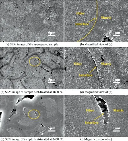
Fig. 1 Microstructure evolution of the high thermal conductivity C/C composites before and after heat-treatment.
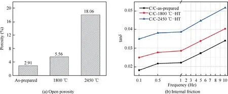
Fig. 2 Structural characterization of defects in the C/C composites before and after heat-treatment.
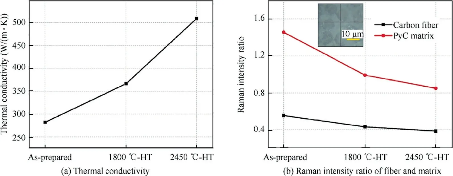
Fig. 3 Thermal conductive property of the C/C composites before and after heat-treatment and its corresponding carbon structure.
Thermal conductivity(λ)of the C/C composites is shown in Fig. 3(a). λ increases continuously from 282 W/(m·K) to 508 W/(m·K), indicating that heat could be transferred more efficiently in C/C composites after heat-treatment at higher temperature. Fig. 3(b) presents Raman intensity ratio (ID/IG)of fiber and matrix in C/C composites.Lower Raman intensity ratio means a higher graphitization degree.ID/IGchanges from 1.45 to 0.85 for PyC matrix as the heat-treatment temperature increased to 2450°C, suggesting that its graphitization degree was significantly improved. Meanwhile, sp2carbon structure of the fiber also became more uniform, with ID/IGdecreased slightly from 0.55 to 0.39. Moreover, the carbon structure between fiber and matrix becomes more matched to reduce interfacial phonon scattering. All of these above were conducive to thermal conductive performance of the C/C composites.
3.2. Ablation behavior of high thermal conductivity C/C composites after heat-treatment
Mass and linear ablation rates of the high thermal conductivity C/C composites are shown in Fig. 4. For Type-I composites,their mass ablation rate decreases from 0.66 mg/s to 0.51 mg/s as the heat-treatment temperature increases up to 2450°C, and their linear ablation rate decreases from 2.95 μm/s to 2.05 μm/s (Fig. 4(a)). Interestingly, as for Type-II composites,both the mass and linear ablation rates increase,from 1.02 mg/s and 3.73 μm/s to 1.28 mg/s and 5.01 μm/s respectively (Fig. 4(b)), which are obviously larger than those of Type-I composites.
Surface temperature during ablation for Type-I composites with fibers vertical to the flame is shown in Fig. 5. After heattreatment at 2450°C, the maximum temperature decreases from 2220°C to 2167°C, which should be related to their improved heat-transfer capacity (Fig. 3(a)). Thermal damage of the C/C composites was consequently reduced due to the declined surface temperature, resulting in the decrease in their mass and linear ablation rates.
Thermogravimetric curve of the mesophase pitch-based carbon fiber is shown in Fig. 6. Its initial oxidation temperature is 744°C and the weight loss rate in air between 800°C and 850°C is 0.142 mg/min. While the weight loss rate for PyC is 1.145 mg/min at 450°C,22indicating that such fibers have higher oxidation resistance than PyC matrix.
Fiber orientation in the C/C composites also influenced their ablation behavior due to the difference in oxidation resistance between fiber and matrix. Schematic fiber and matrix distribution during ablation is shown in Fig. 7. The area ratio in the field of view represents the relative content of PyC matrix to fibers, which also represents the degree of structural integrity under ablation.For samples with fibers vertical to the oxyacetylene flame, area ratio of the exposed PyC was greatly reduced during ablation due to the blocking of fibers. The exposure probability of pores to the flame also decreased largely since such pores mainly existed at the fiber/matrix interfaces (Fig. 7(a)). When more fibers were exposed to the flame during ablation, the depression rate at the interface would be reduced and the ablation rates in Type-I composites decreased consequently. While for C/C composites with fibers parallel to the flame, the fiber/matrix interfaces were directly faced to the oxyacetylene torch so the ablation occurred more easily and thermal damage of the C/C composites increased greatly (Fig. 7(b)).
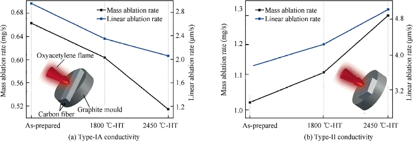
Fig. 4 Mass and linear ablation rates of the high thermal conductivity C/C composites before and after heat-treatment.

Fig. 5 Surface temperature-rise of C/C composites with fibers vertical to the flame during the ablation test.

Fig. 6 Thermogravimetric behavior of the mesophase pitchbased carbon fiber in air.
Surface morphology of the most severely ablated position in C/C composites is shown in Fig.8.The PyC matrix was consumed rapidly as ablation time prolonging due to its poor oxidation property (Fig. 6). The fiber/matrix interfaces were preferentially ablated, resulting in the formation of interface gaps. Then the formed gaps would provide access to the oxyacetylene flame and accelerate its denudation.For Type-I composites,less fiber/matrix interfaces were exposed the erosion of oxyacetylene torch, so they exhibit better ablation performance. Distinct ablation morphologies can also be observed depending on their heat-treatment temperature. For the composites without heat-treatment, heat of oxyacetylene torch was easily concentrated on the ablated surface because of their lower thermal conductivity, resulting in the appearance of a large and deep pit (Fig. 8(a)). After heat-treatment at 1800°C, the increase of thermal conductivity improved the ablation performance significantly. The ablation pit became smaller and existed together with fissures since more heat was transferred to other parts in the composites, as shown in Fig. 8(b). As for the samples heat-treated at 2450°C, only ablated fissure existed(Fig.8(c)).Compared with Type-I composites, thermal damage under ablation for the as-prepared samples with fibers parallel to the flame was much larger since PyC matrix and fiber/matrix interfaces were always exposed to the flame. So a concave contour morphology was formed at F/M interfaces and only the ablated fibers were observed(Fig. 8(d)). Based on the discussions above, the good ablation performance of Type-I composites can be mainly attributed to the improved heat-dissipation capability caused by heattreatment and the less exposed defects, which could efficiently reduce the heat concentration of oxyacetylene torch and weaken its denudation.
For Type-II composites with fibers parallel to the flame,their surface temperature and ablation rates increased with higher heat-treatment temperature, which might be resulted from the increased exposed defects facing to the oxyacetylene torch. In order to verify this deduction, graphite samples with a porous structure were obtained via pre-oxidation treatment at 900°C in air for 10 min. Size of the graphite bulk is equivalent to that of C/C composites, which is 12 mm×12 mm×3 mm. The porosities before and after micro-oxidation treatment are 9.9% and 22.3% respectively.Then the ablation test was performed using an oxyacetylene torch for 40 s with O2and C2H2flow rate of 0.24 L/s and 0.16 L/s respectively.Surface morphology of the graphite samples is shown in Fig. 9. There are some small pores inside the original graphite (Fig. 9(a)) and these pores are enlarged after pre-oxidation treatment (Fig. 9(b)). With larger porosity, the maximum surface temperature during ablation increases from 1982°C to 2094°C (Fig. 9(c)), and the mass and line ablation rates of the oxidized sample also increase greatly,almost twice as those of the original one (Fig. 9(d)). These results indicate that more micro-defects would cause more severe ablation for carbon-based materials, further verifying a lower ablation resistance of Type-II composites than that of Type-I composites.
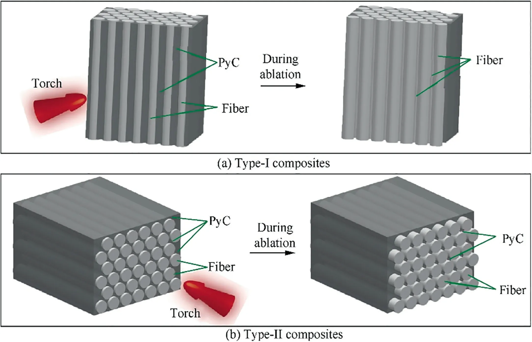
Fig. 7 Schematic fiber and matrix distribution during ablation in the high thermal conductivity C/C composites.
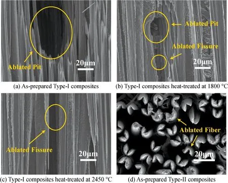
Fig. 8 Surface morphology of the high thermal conductivity C/C composites after ablation.
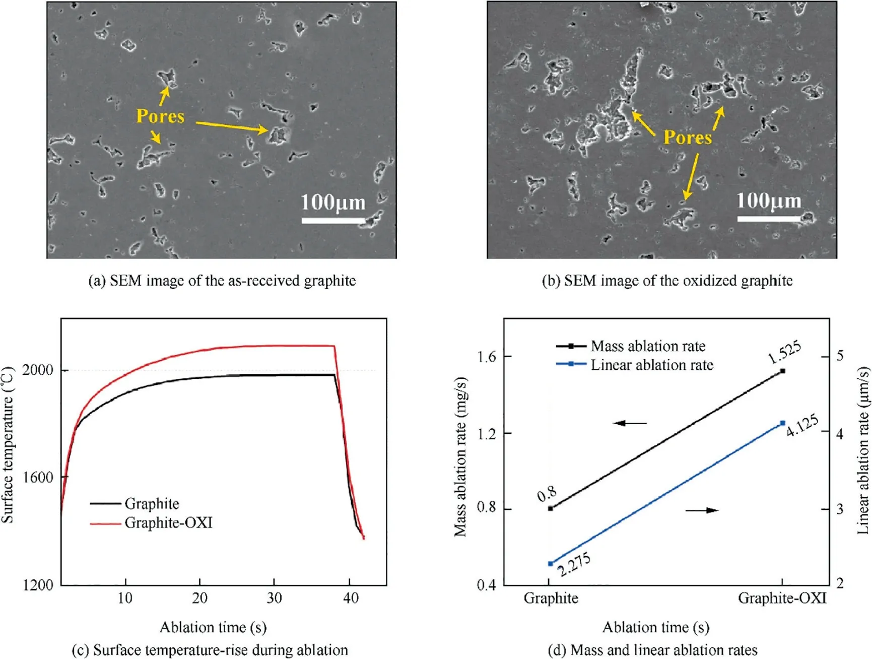
Fig. 9 Ablation behavior of the comparative graphite samples.
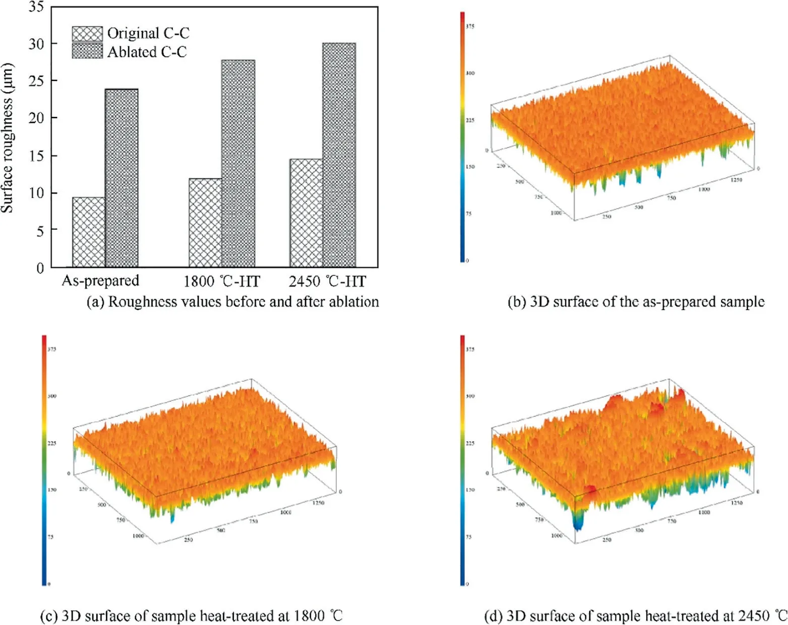
Fig. 10 Surface roughness of the high thermal conductivity C/C composites after ablation.
Surface roughness of Type-II composites is shown in Fig. 10. It is significantly different for samples heat-treated at varied temperatures, from 9.36 μm to 14.51 μm. Such Ra change is consistent with the large difference in porosity and F/M interfacial state of the C/C composites. By observing the 3D view of surface roughness for the composites after ablation,where pores exist between the peak(in orange color)and the valley (in green color), it is found that amounts and depth of the pores are larger for the samples heat-treated at higher temperature (Fig. 10(b)-(d)). While Ra increases with similar incremental value within range of 14.6-15.6 μm for all of the C/C composites after ablation, suggesting that the initial micro-structural difference played an important role on their subsequent ablation behavior (Fig. 10(a)), which is also confirmed by the designed ablation experiment of graphite. So compared with Type-I composites, the poor ablation performance of Type-II are resulted from the more exposed defects especially fiber/matrix interface gaps. With the increase of heat-treatment temperature, much more defects were formed in Type-II composites and exposed to the oxyacetylene torch,resulting in the performance degradation.
4. Conclusion
Uni-directional C/C composites with high thermal conductivity were prepared by CVI. After heat-treatment at 2450°C,thermal conductivity of the C/C composites increased from 282 to 508 W/(m·K)due to more uniform sp2carbon structure in fiber and PyC matrix,though more micro-structural defects were formed at the F/M interfaces and in the matrix.For composites with fibers vertical to the oxyacetylene torch, the maximum surface temperature decreased from 2220°C to 2167°C due to the greatly increased heat-transfer capacity after heattreatment. Meanwhile, more mesophase pitch-based carbon fibers with better oxidation resistance would be exposed to the flame during ablation.All of these led to their mass and linear ablation rates decreased from 0.66 mg/s and 2.95 μm/s to 0.51 mg/s and 2.05 μm/s separately. While for the C/C composites with fibers parallel to the torch, interfaces and pores were always exposed to the flame during the whole ablation test. Larger micro-structural defects due to the heattreatment resulted in the increased mass and linear ablation rates, from 1.02 mg/s and 3.73 μm/s to 1.28 mg/s and 5.01 μm/s respectively.
Acknowledgements
This work was supported by the National Natural Science Foundation of China [grant numbers 51572223, 51727804].
Appendix A. Supplementary data
Supplementary data to this article can be found online at https://doi.org/10.1016/j.cja.2019.07.017.
 CHINESE JOURNAL OF AERONAUTICS2020年5期
- CHINESE JOURNAL OF AERONAUTICS的其它文章
- Experimental of combustion instability in NTO/MMH impinging combustion chambers
- Three-line structured light vision system for non-cooperative satellites in proximity operations
- Remaining useful life prediction of aircraft lithium-ion batteries based on F-distribution particle filter and kernel smoothing algorithm
- Flow characteristics around airfoils near transonic buffet onset conditions
- Experimental investigation of flow and distortion mitigation by mechanical vortex generators in a coupled serpentine inlet-turbofan engine system
- An improved prediction model for corner stall in axial compressors with dihedral effect
