Multi-disciplinary design optimization with fuzzy uncertainties and its application in hybrid rocket motor powered launch vehicle
Pengcheng WANG, Hui TIAN, Hao ZHU,*, Guobiao CAI
a School of Astronautics, Beihang University, Beijing 100083, China
b Key Laboratory of Spacecraft Design Optimization & Dynamic Simulation Technologies of Ministry of Education,Beihang University, Beijing 100083, China
KEYWORDS Fuzzy theory;Hybrid Rocket Motor(HRM);Launch Vehicle (LV);Sensitive Analysis (SA);Uncertainty-based Multidisciplinary Design Optimization (UMDO)
Abstract In this paper, an Uncertainty-based Multi-disciplinary Design Optimization (UMDO)method combining with fuzzy theory and Multi-Discipline Feasible (MDF) method is developed for the conceptual design of a Hybrid Rocket Motor (HRM) powered Launch Vehicle (LV). In the method proposed, membership functions are used to represent the uncertain factors, the fuzzy statistical experiment is introduced to analyze the propagation of uncertainties, and means, standard deviations and credibility measures are used to delineate uncertain responses.A geometric programming problem is solved to verify the feasibility of the Fuzzy-based Multi-Discipline Feasible(F-MDF) method. A multi-disciplinary analysis of a three-stage HRM powered LV involving the disciplines of propulsion, structure, aerodynamics and trajectory is implemented, and the mathematical models corresponding to the F-MDF method and the MDF method are established. A two-phase optimization method is proposed for multi-disciplinary design optimization of the LV,including the orbital capacity optimization phase based on the Ziolkowski formula,and the scheme trajectory verification phase based on the 3-degree-of-freedom point trajectory simulation.The correlation coefficients and the quadratic Response Surface Method(RSM)based on Latin Hypercube Sampling (LHS) are adopted for sensitive analysis of uncertain factors, and the Multi-Island Genetic Algorithm (MIGA) is adopted as the optimization algorithm. The results show that the F-MDF method is applicable in LV conceptual design, and the design with the F-MDF method is more reliable and robust than that with the MDF method.
1. Introduction
The conceptual design of Launch Vehicles (LVs) usually involves coupling of multi-disciplines. Traditionally, the Multi-disciplinary Design Optimization (MDO) method is used to shorten design periods through coordination of multiple disciplines.1Compared with practical engineering observation, however, vast design model parameters contain uncertainty which is potentially caused by machining errors,waves of material physical property parameters, decisions and cognitions of designers, etc.2, and will thus cause irreversible deviation or excessive redundancy degree in a conceptual design, especially in the aerospace field.3
Uncertainty-based Multi-disciplinary Design Optimization(UMDO)is an effective method to solve the problem above,4,5and has been increasingly used in the aerospace field. Magnin et al. used the Monte Carlo analysis method and simulated annealing algorithm for the satellite system, and found the scheme with the UMDO method being better than the scheme for MDO and the original scheme with the same reliability.6Fatemi et al.conducted a study on the re-entry vehicle considering integrated trajectory uncertainties, and confirmed uncertainties have significant influence on responses and provided a superior integrated design scheme.7Zhu et al. considered a hybrid rocket motor as the Ascent Propulsion System, and proved that the probabilistic-based method can make conceptual designs more reliable and robust.8These UMDO approaches mentioned above basically take into account the uncertain factors according to the stochastic theory.
However, uncertainties caused by decisions and cognitions from designers,including the boundaries and distributions,are lack of sufficient uncertainty information. Therefore, the stochastic theory is unadaptable for these uncertainties, and the fuzzy theory can be applied for quantification of decisions and cognitions uncertainties after established by Zadeh.9Applications of the fuzzy theory in the engineering field are investigated in only a few papers. Mourelatos and Zhou compared uncertainty-based design optimization results using the fuzzy model and the probabilistic model, and demonstrated feasibility as well as conservatism of the credibility theory.10Moreover, fuzzy optimization has been applied in of the research on mechanical structure reliability.11-13Considering considerable uncertainties of decisions and cognitions, it becomes an urgent problem that how to improve reliability and robustness of an LV conceptual design under the premise of maintaining good performance.
The Hybrid Rocket Motor (HRM), which uses liquid oxidizer and solid fuel for power and has the advantages such as safety, simplicity, reliability, thrust regulation, multiple restart capability and low cost, is chosen as the power system of the LV in this paper.14Accordingly,the small LVs powered by the HRM for the microsatellite can achieve low cost,quick response and high reliability,which has attracted special attention in the space launch market.15-17Related studies,including studies on thrust control and combustion particle-gas influencing nozzle, are conducted from similar research(as Ref.18,19shown).
In this paper, a Fuzzy-based Multiple Discipline Feasible(F-MDF)approach is proposed,combining with the fuzzy theory and the Multiple Discipline Feasible(MDF)method.This new approach is firstly verified by comparing with the deterministic MDF method through application for a classical geometric programming problem. Then, both approaches are investigated in the conceptual design of the LV propelled by the HRM to improve vehicle design robustness and reliability.
The remainder of this paper is organized as follows.In Section 2, the F-MDF approach is proposed and verified by an example. Then the multi-disciplinary model of the HRM propelled the LV is developed,and the uncertain factors of LV are modeled and analyzed in Section 3. The two-phase LV optimization method is proposed in Section 4, and the mathematical models for optimization of the LV using MDF and FMDF are presented. In Section 5, the optimization results and comparison of two optimization methods are given, and the scheme trajectories of two LVs are demonstrated as well.
2. Fuzzy-based optimization approach
In a typical UMDO optimization, uncertainty modeling,uncertainty analysis,and optimization methods can contribute to study of uncertainties, propagation exploration, and optimal solution search, respectively. A novel fuzzy-based optimization method is developed by integrating the fuzzy theory with uncertainty modeling and analysis. Then, this method is tested by an example,and the results are discussed for feasibility and robustness of objective value.
2.1. Uncertainty modeling based on fuzzy theory
In the fuzzy theory,the membership function is used to model fuzzy uncertainties,9while credibility measure is a representation used to model fuzzy uncertain responses.9,20-22Fig. 1 shows several classic membership functions and their curves used in this paper, where A(x) is the membership function of fuzzy uncertain input x; a, b, c and d in the figure are used to describe the characteristic values of variables; σ is the standard deviation of Gaussian distribution.
2.2. Uncertainty analysis based on fuzzy statistical experiment
In the fuzzy theory,the mean μ(y)and standard deviation σ(y)of the response can be acquired seriatim by
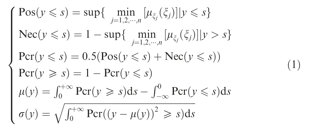
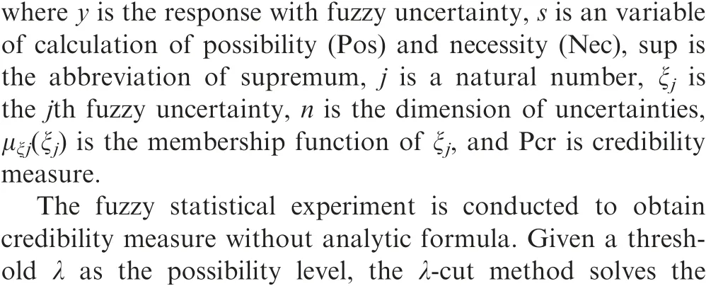
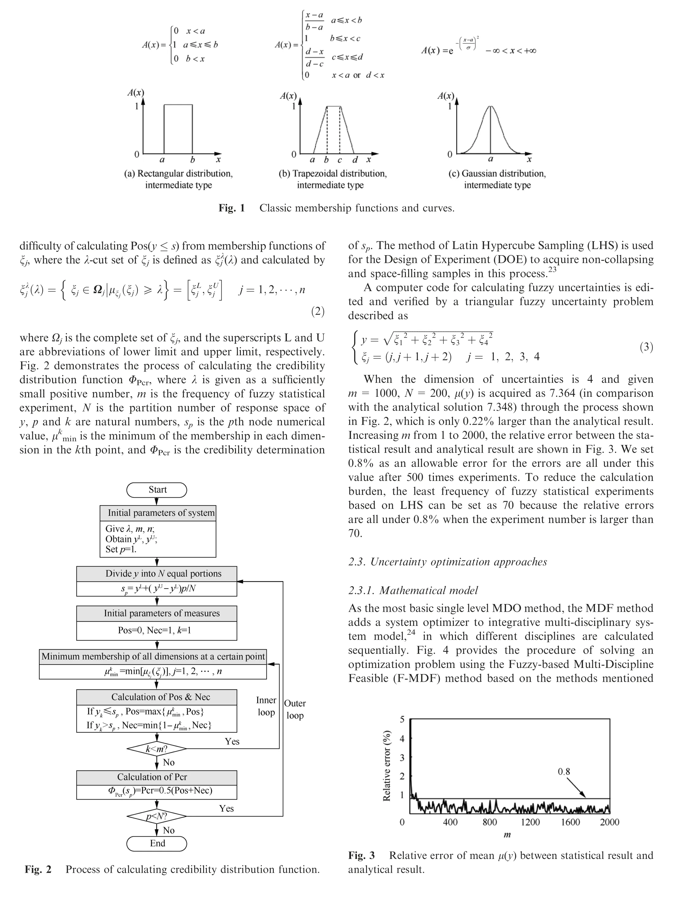
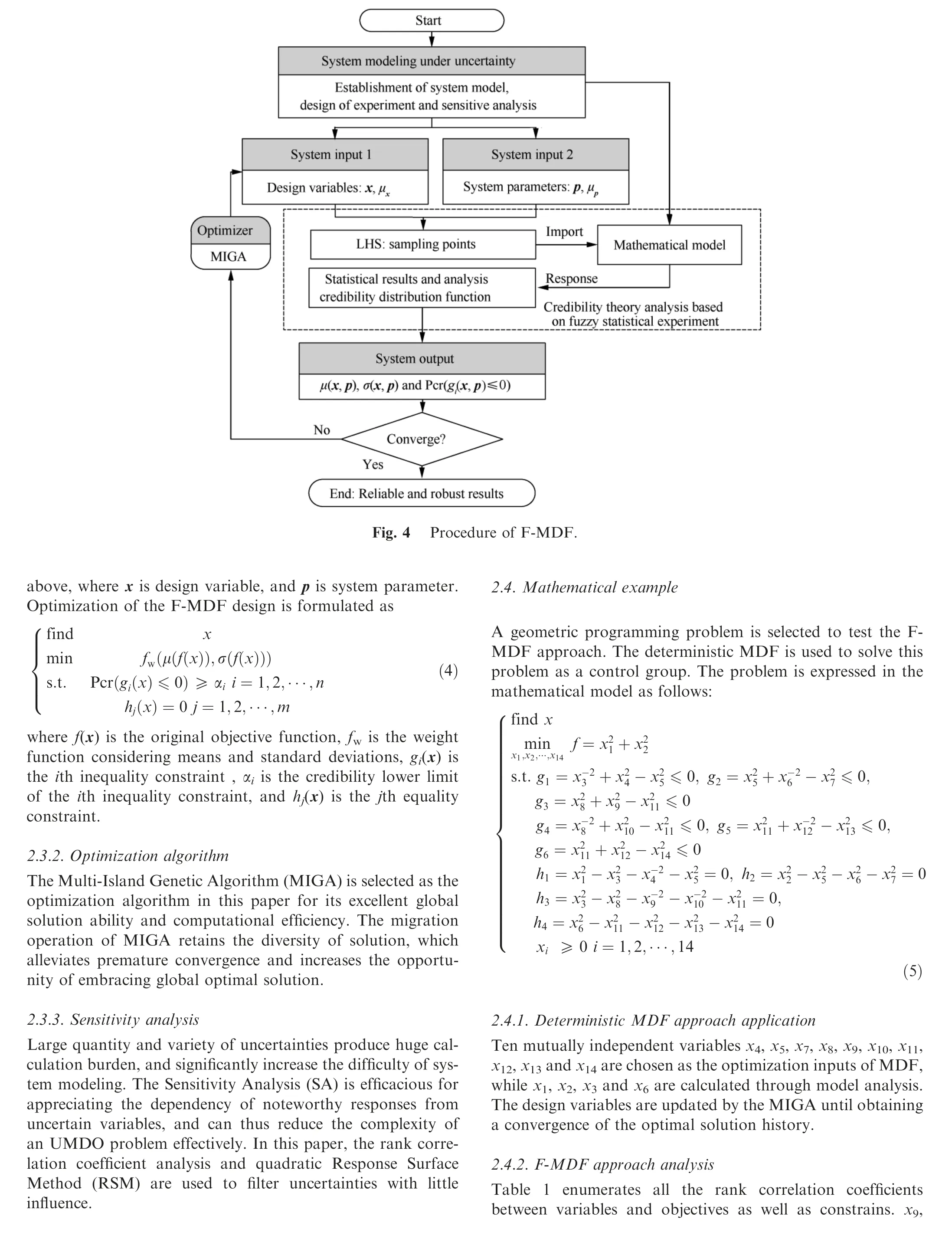


Table 1 Rank correlation coefficient between variables and responses.
The fuzzy distribution,type,lower bound and upper bound of each uncertain variable are set as shown in Table 2. The objective function in the F-MDF approach includes the mean and standard deviation, which can ensure a low degree of dispersion,while μ(f),σ(f)and credibility measures of constraints are acquired according to the parameter statistics of all experiment results. The uncertainty-based optimization with the FMDF method is formulated as

2.4.3. Results and discussion of example
The convergence criterion is set as the deviation of the objective value smaller than 10-3during five consecutive times.This geometric programming problem has a globally unique optimal theoretical solution ftheo=17.5887.The results are shown in Table 3. For comparison of reliability and robustness,responses (x1, x2, x3and x6) and constraints (g1-g6) of the MDF results are recalculated using the F-MDF mathematical model with the MDF optimal inputs.
According to Table 3, the relative difference of the means between fMDFand ftheois 0.2%, which proves a good global optimization ability of the MDF method. All the credibility measurements of constraints being satisfied with the F-MDF method satisfy the constraints (≥0.95), and five of six constraints exhibit an extremely high reliability (≥0.9991), which is significantly higher than that with the MDF method and the theoretical solution (≤0.51). This shows that the F-MDF approach can acquire the optimal result more robustly and more reliably. However, fF-MDFpossesses a bigger mean (not exceeding 3.7%) of objective than fMDFand ftheo, which indicates that a more reliable and more robust result requires a condign sacrifice of the objective function value.
3. LV modeling and uncertain analysis
3.1. Conceptual design configuration
The reference mission for this study is to reach a 300 km circular orbit with a 100 kg payload.The LV designed in this paper consists of three propulsion stages powered by the HRM,two inter stage cabins, and a head module (including a payload,payload adapters, electronic avionics, and attitude control equipment),as shown in Fig.5.Without wings,the flight control depends on the swing nozzle and attitude and orbit control engines.
The carbon fiber composite and aluminum alloy are adopted to reduce structural mass. A combination of 98%hydrogen peroxide (H2O2diluted with water) as oxidizer and Hydroxyl-Terminated Poly Butadiene (HTPB) as fuel is used for propellant in each HRM.
3.2. Disciplinary analysis and modeling
Four main disciplines referenced in the conceptual design process of LV are considered in this paper, including propulsion,structure, aerodynamic and trajectory. A sequential analysis model is developed as shown in Fig. 6, which also outlines the interdisciplinary relation.

Table 3 Variables and results of mathematical example.

Fig. 5 Conceptual configuration of a three-stage LV.
3.2.1. Propulsion
An integrated program is developed and the main processes,including the grain design, preliminary design of the thrust chamber and interior ballistic calculation,are proposed in previous study.25Through this program,the main performance of the HRM can be acquired from the design variables(including the outer diameter of grain column in HRM Dfi,the thickness of grain column in HRM ei,the initial force Fii,the initial oxygen fuel ratio OFii, the expansion ratio of nozzle εi, where the subscript i equals 1,2 or 3,representing stage number 1st,2nd,3rd respectively),and system design parameters(such as densities and yield limits). All the design variables and their ranges are shown in Table 4.
3.2.2. Structure
In this section, the dimension and weight of LV are obtained with the formula as follows:

where m0is the lift-off mass, miis the mass of the ith stage,mfairingis the mass of fairing, mpayloadis the mass of payload,l0is the total length of LV, liis the length of the ith stage,and lfairingis the length of fairing. In each stage, propellant mass is acquired from interior ballistic calculation in the propulsion discipline, and thus the masses and sizes of the main components (including the chamber, nozzle, oxidizer tank, gas cylinder, etc.) are calculated by a structure sizing and weighting program.25Other masses and sizes of extra structures (including pipes and valves, flight control electrical subsystem, inter stage cabins, separation mechanism and attitude control engine,fairing and payload adapter)in each stage are assumed based on engineering experience.The 1st and 2nd stages adopted series-mode frame,while the 3rd stage adopted the parallel structure, as illustrated in Fig. 7.
3.2.3. Aerodynamics
The 1976 U.S. standard atmosphere model, which contains models for atmosphere temperature, atmosphere pressure,and atmosphere density with height,26is used in this paper.The aerodynamic formulas based on Titan II at small angles of attack27are adopted for the drag coefficient CDand lift coefficient CLα.
3.2.4. Trajectory
A 3-degree-of-freedom point trajectory is implemented in the trajectory. The position r can be calculated according to Eq. (8), where t0=0 is the initial position of launch point,V is the velocity in velocity coordinate, a is the acceleration along x-coordinate in the launch coordinate,V0=0 is the initial velocity of LV, mtis the rocket mass, P is thrust in the launch coordinate(including controlling force)and is obtained by propulsion discipline analysis,N is aerodynamic force in the launch coordinate and is calculated by the aerodynamic coefficients given in the aerodynamics discipline.g,ae,acare acceleration in launch coordinate caused by gravity,carrier inertial force,and Coriolis inertia force, respectively, m0is the takeoff mass, and ṁ is the mass flux of the propellant.

Fig. 6 Relationships between disciplines.
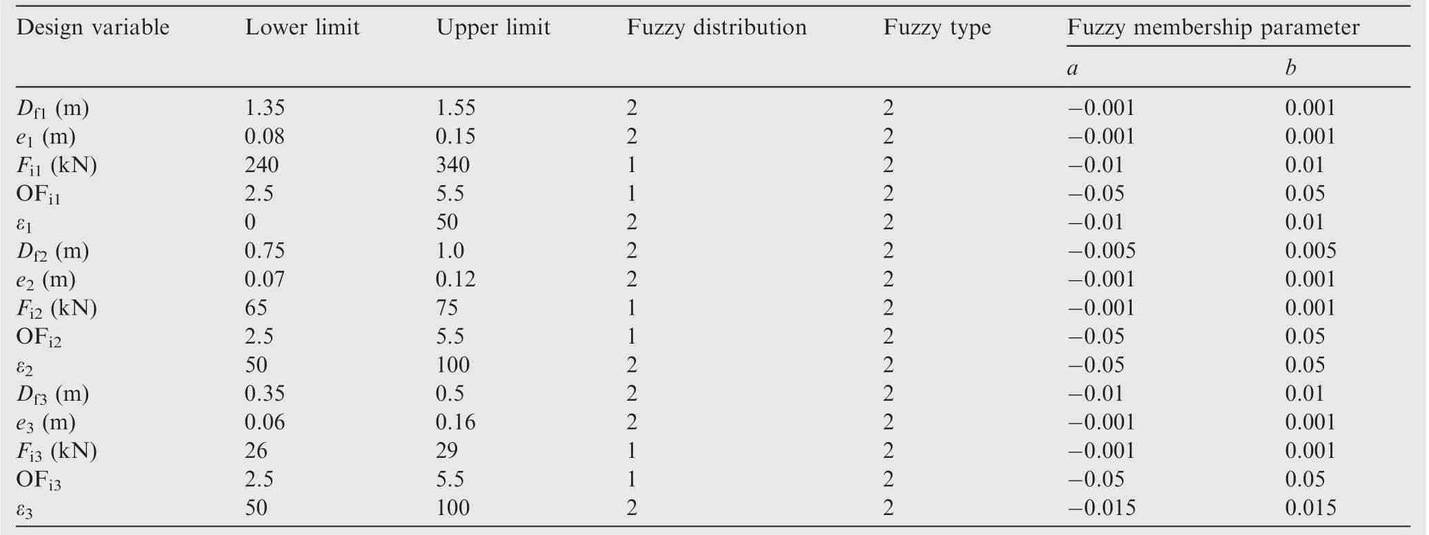
Table 4 Ranges and uncertain distribution parameters of variables.

Fig. 7 Detail configuration of three-stage hybrid LV.

The trajectory consists of a vertical taking-off phase,a program turn phase, a zero attack angle flight phase, and a program pitch phase until the payload are released into the orbit. The pitch angle φ, the attack angle α, and trajectory tilt angle ϑ of the four phases are sequentially given as follows:
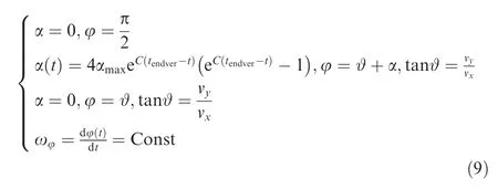
where αmaxis the maximum absolute value of the attack angle in the subsonic phase, C is a constant coefficient, tendveris the end time of vertical taking-off phase, vyis the velocity in ydirection, vxis the velocity in the x-direction, and ωφis the pitch angular velocity.
3.3. Fuzzy-based uncertainty modeling
3.3.1. Uncertainty classification and quantification
Confidentiality of the aerospace system means that few design data can be acquired through the public,and thus it is difficult to acquire fuzzy membership through data mining. In this paper, uncertainties are divided into three categories: design variable uncertainties, measurable system parameter uncertainties, and unmeasurable system parameter uncertainties.Tables 4-7 enumerate uncertain representations (including fuzzy distribution, type and uncertain parameters) of uncertainty inputs refer to design criteria and engineering experience.28-30In these tables, a, b, c and d have the same definitions as those in Fig. 1. In the column of fuzzy distribution in the tables, 1, 2 and 3 represent rectangle, normal and trapezoid distribution, respectively. In the column of fuzzy type in these tables, 1, 2 and 3 represent small-scale, intermediate and big-scale types, respectively. The rest of the paper no longer illustrates the meaning of the numbers in the type and distribution columns to avoid redundancy.
15 design variable uncertainties of the whole LV are given in Table 4. Table 5 enumerates measurable the system parameter uncertainties of the 1st stage, which are mainly caused by fluctuations of material properties and manufacture deviations.Parameters p01to p08are densities of different materials,including structure and propellant, which change little with temperature and pressure. Parameters p09to p11are manufacture parameters, which are mainly related to machining error and operation environment. All parameters in Table 5 canbe observed through scientific measurement, and hence have accurate values and small uncertain fluctuation range.

Table 5 Property uncertainties in 1st stage HRM.
The uncertain parameters of the 2nd and 3rd stages have the same value as those of the 1st stage,and thus the LV totally contains 33 uncertainties of this kind. Therefore, the above parameters are described as normal distributions and intermediate types based on experience.
Table 6 enumerates the uncertainties arising from decisions and cognition from the designers, and these uncertainties are unmeasurable system parameters of the 1st stage. These parameters are accompanied by subjective uncertainties (such as insufficient cognition and human impact) and are thus impossible to be measured or directly estimated. Based on the engineering experiences, the membership functions of all these uncertainties are shown in Table 6.Considering the practical engineering, uncertain parameters under the same category of the 2nd and the 3rd stage have the same value as those of the 1st stage, except for the coefficient of the tank residual oxidizer(p17,as shown in Table 7)because of obvious difference among oxidizer tank volumes at different stages.Thus,the launch vehicle totally contains 78 parameters of this kind in total.
3.3.2. Uncertainty parameters analysis
To reduce the computational cost,two kinds of Sensitive Analysis (SA) methods of the above-mentioned three types of uncertain factors are carried out to filter out low-impact factors,and this will retain the uncertainties with significant influence on system responses. Correlation coefficient method is used to analyze design variable uncertainties in Table 4,which can directly take advantage of deterministic optimization results and increase efficiency. The quadratic RSM based on LHS is employed for other uncertainties.
The length to diameter ratio LD of an LV determines the control performance and the aerodynamics characteristics.Large LD may cause over strict requirement of control capability, while small LD can be optimized for smaller aerodynamic drag. The minimum force-mass ratio FMi(subscript i=1, 2, 3 is the stage number) during each stage of flight phase should be greater than a constant value for good acceleration.The takeoff mass m0is usually used to judge the design advancement of a rocket. The theoretical velocity increment Vtheoof a designed LV ensures the capability of transport payload at preset orbit. Outputs mentioned above are considered as objects of SA.
Table 8 represents the rank correlation coefficients of the MDF results, and directly provides the dependency of important outputs from design variables. As the global search algorithm is adopted for the MDF optimization, the results are considered representative.Six items are selected as design variable uncertainties for the F-MDF method: the initial force(Fil),the thickness of grain column(e1)and the outer diameter of HRM grain column(Df1)of 1st stage,the thickness of grain column (e2) of 2nd stage, and the thickness of grain column(e3) and the outer diameter of HRM grain column (Df3) of 3rd stage.
For the SA of system parameter uncertainties,the fuzzy statistical experiment is conducted with LHS. Thus 1000 sample points are generated and imported into the calculation model of the LV. Among the outputs, FMi(i=1, 2, 3) is replaced with the takeoff force-mass ratio FM0for judging system parameters influences. Fig. 8 lists the top 10 factors against the main performance parameters (including m0, LD, Vtheoand FM0), where the black color represents the positive number,while the white color represents the negative number.The results show that the most affected factors of m0are the oxidizer mass flux exponent (p13) at the 1st and 2nd stages. In Fig. 8(b), all the top 10 influence factors of LD cover 3 items:the regression rate coefficient (p12), the fuel density (p01), and the oxidizer density (p02) of the 1st stage. Vtheodependents 3 system parameters most: the chamber heat insulation layer thickness (p25), the minimum machining thickness of chamber and nozzle shell material (p29), and the minimum machining thickness of oxidizer tank shell material (p30) of the 3rd stage.FM0shows definite association with m0, and three main factors of FM0are the regression rate coefficient (p12) of the 1st stage, the oxidizer mass flux exponent (p13) of the 1st and 2nd stages.
In summary, 8 items are selected as system parameter uncertainties in F-MDF: the regression rate coefficient (p12),the oxidizer mass flux exponent (p13), the fuel density (p01),and the oxidizer density (p02) of 1st stage; the oxidizer mass flux exponent (p13) of 2nd stage; the chamber heat insulation layer thickness (p25), the minimum machining thickness of chamber and nozzle shell material (p29), and the minimum machining thickness of oxidizer tank shell material (p30) of the 3rd stage.
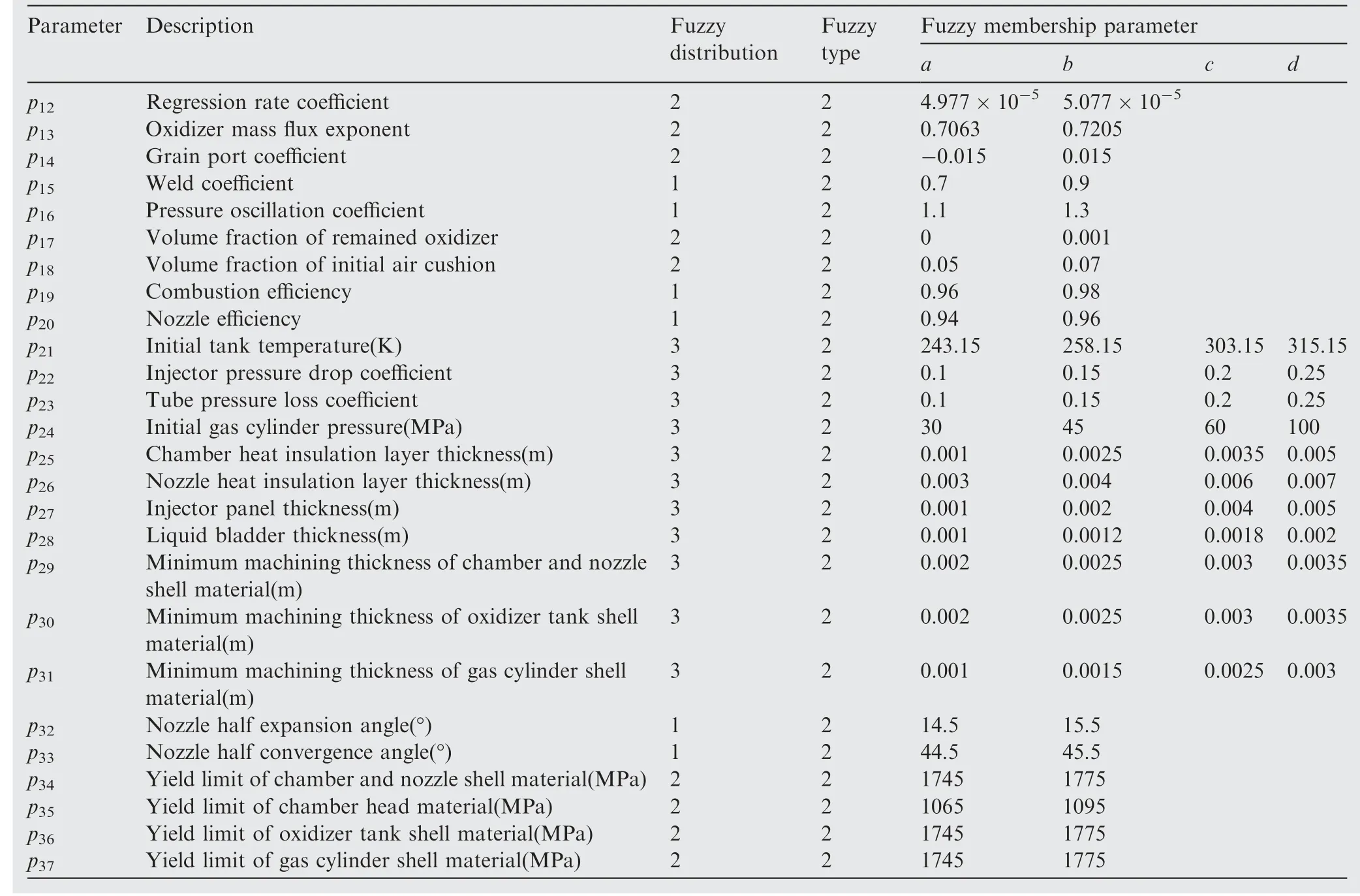
Table 6 Decision and cognition uncertainties in 1st stage HRM.

Table 7 Different decision and cognition uncertainties in 2nd and 3rd stage HRM.
4. LV design optimization
To obtain a feasibility scheme trajectory for a definite LV, an optimal operation is usually performed with many iterations and with a long time.A whole design optimization of LV produces a definite LV design at each history point, which means the total number of operations is achieved from multiplying trajectory optimization iterations by LV design optimization iterations in an integral calculation model including all disciplines. However, non-feasible design (such as not satisfactory constraints) and non-optimal solutions are meaningless, and such huge calculation cost may cause unacceptable demands.
A two-phase LV optimization method is proposed in this section to solve the problem of huge trajectory integral calculation effectively, as shown in Fig. 9. The two phases are the Orbit Capacity Calculation(OCC)phase and the Scheme Trajectory Verification(STV) phase.In the OCC phase, considering propulsion and structure, trajectory is neglected and the final velocity is calculated by the Ziolkowski formula to judge ability to orbit. In the STV phase, considering aerodynamic,a scheme trajectory is achieved by optimization to verify feasibility of the LV design in the precious phase. The feasible solution in the STV phase proves the feasibility of optimal LV design in the OCC phase. To avoid premature convergence,the MIGA is selected as the optimization algorithm in both phases.
4.1. OCC phase
4.1.1. MDF design optimization
In the OCC phase, Table 4 indicates selected design variables representing shapes(Df,e)and determining propulsion performance(Fi,ε,OFi)of each HRM.Their bounds are assumed by referring to LVs at the same level.m0is the parameter that can measure the advanced degree of a launch vehicle, and thus is considered as an objective function.Constrains are consideredas the capability of payload into the mission orbit, the good acceleration of each stage, and the proper length to diameter ratio. Thus the mathematical model for LV design optimization with MDF method is formulated as
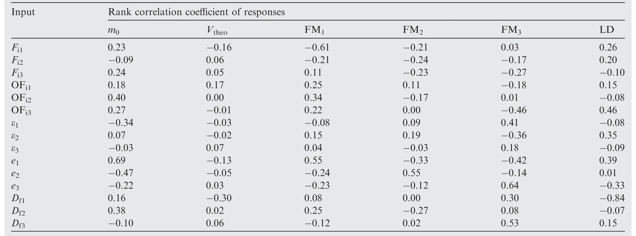
Table 8 Rank correlation coefficient of MDF results.
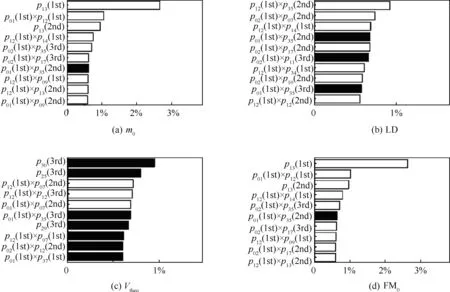
Fig. 8 Sensitivity analysis of responses.
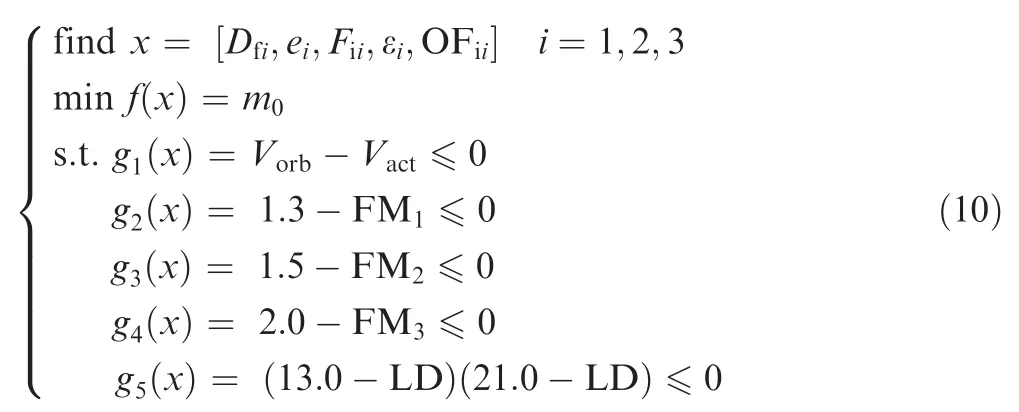
where Vorbis the velocity increment needed at the 300 km circular orbit, Vactis the actual velocity increment, and FMi(subscript i is the stage number) is the minimum force-mass ratio during each stage flight.
4.1.2. F-MDF design optimization
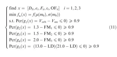
Design variable uncertainties and high-impact system uncertainties are treated as uncertain inputs,and these uncertainties are quantized based on the membership function in F-MDF procedure. The target function and constraints are considered as the fuzzy response(mean and standard deviation)and credibility measures, respectively. Design robustness is ensured by minimizing the function value containing the mean and standard deviation of m0. At the same time the design reliability is ensured by credibility measure of constraints satisfying degree larger than 0.9. The mathematical model of F-MDF optimization is formulated as
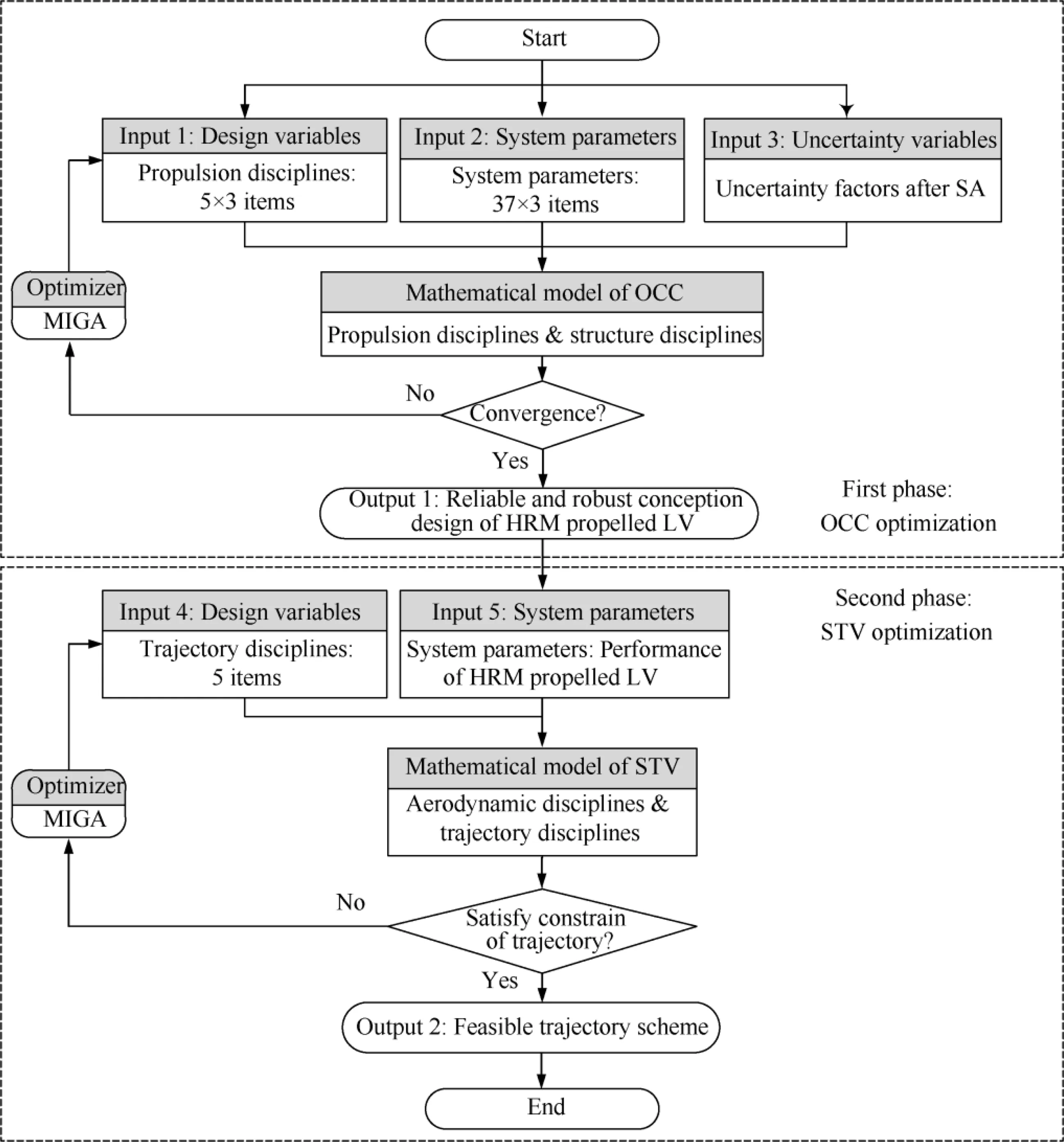
Fig. 9 Process of F-MDF system design.
4.2. STV phase
Table 9 provides the design variables and their ranges in the STV phase, where αmax1is the maximum attack angle during the program turn phase, C1is the control parameter of attack angle during the program turn phase, ωφ2and ωφ3are the pitch angular velocities during vacuum flight phase of the 2nd and the 3rd stage flights respectively,tglide2is the glide time between the 2nd and the 3rd stage flight. These variables represent the parameters of optimized flight trajectory in each stage as Eq. (8) shown. The eccentricity of final orbit Eccorb,who judges the roundness of orbit,is set as the objective as well as one constraint(≤0.05%)for an extra guarantee.In order to release the payload to the target orbit, the relative difference value between the actual orbit height and performance index height below 5%.
18 system parameters depicting the LV property in the STV phase are required from the OCC phase: the stage mass, the effective propellant mass,the average force,the average specific impulse, the working time and the outer diameter in each HRM stage. The trajectory of the LV is determined by Eq.(8)and the mathematical model of the STV phase is shown aswhere ΔH is the difference between the actual orbit height and performance index height and Horbis the height of index orbit.

Table 9 Design variables and ranges in STV phase.
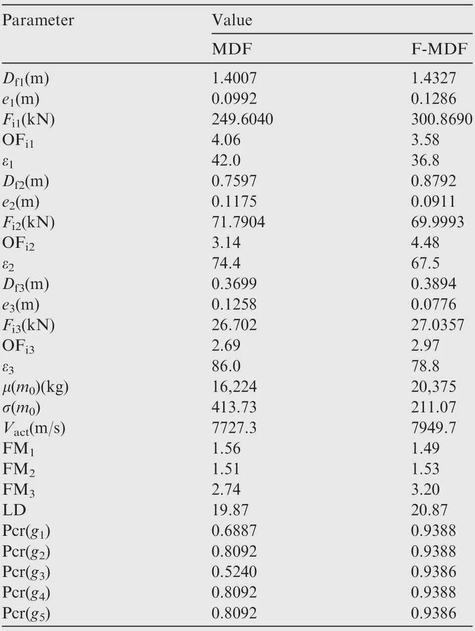
Table 10 Optimal LV designs.

5. Results and discussion
5.1. OCC results
5.1.1. Comparison of two optimization approaches
Similar to example in Section 2.4.3, the variables of the MDF optimization are reimported into the F-MDF calculation model for acquiring credibility measurements of the target and constrains.Table 10 shows the results of the two methods.The credibility measures of F-MDF constrains are all above 0.93 (in comparison to 0.52-0.81 for the MDF), which proves improvement of reliability.The standard deviation of F-MDF results is 211.07(in comparison to 413.73 for the MDF),which proves significant increase of robustness as well as remarkable reduction risks of irreversible failure caused by deviation after production.
The value g1of F-MDF method is -223.897 (in comparison to -1.508 for the MDF) shows conservatism of velocity increment in the uncertain design. Thus, inaccuracy of Vactcaused by velocity waste based on experience can be reduced to improve the reliability of LV injection.
5.1.2. LV performance analysis
Table 11 presents some performances of two optimal schemes.These data describe the size of each stage HRM that can launch 100 kg payload to 300 km orbit and provide worthy reference for the designers.
Within 5% changes for all parameters of HRM in the 2nd stage illustrates that the 2nd stage of LV has small influences on reliability and robustness increment. In scheme under uncertainties,the geometric profile of the 1st stage is obviouslyenlarged, including 37.8 % increment of stage mass, 15.3%increment of working time and 20.3% increment of average force.
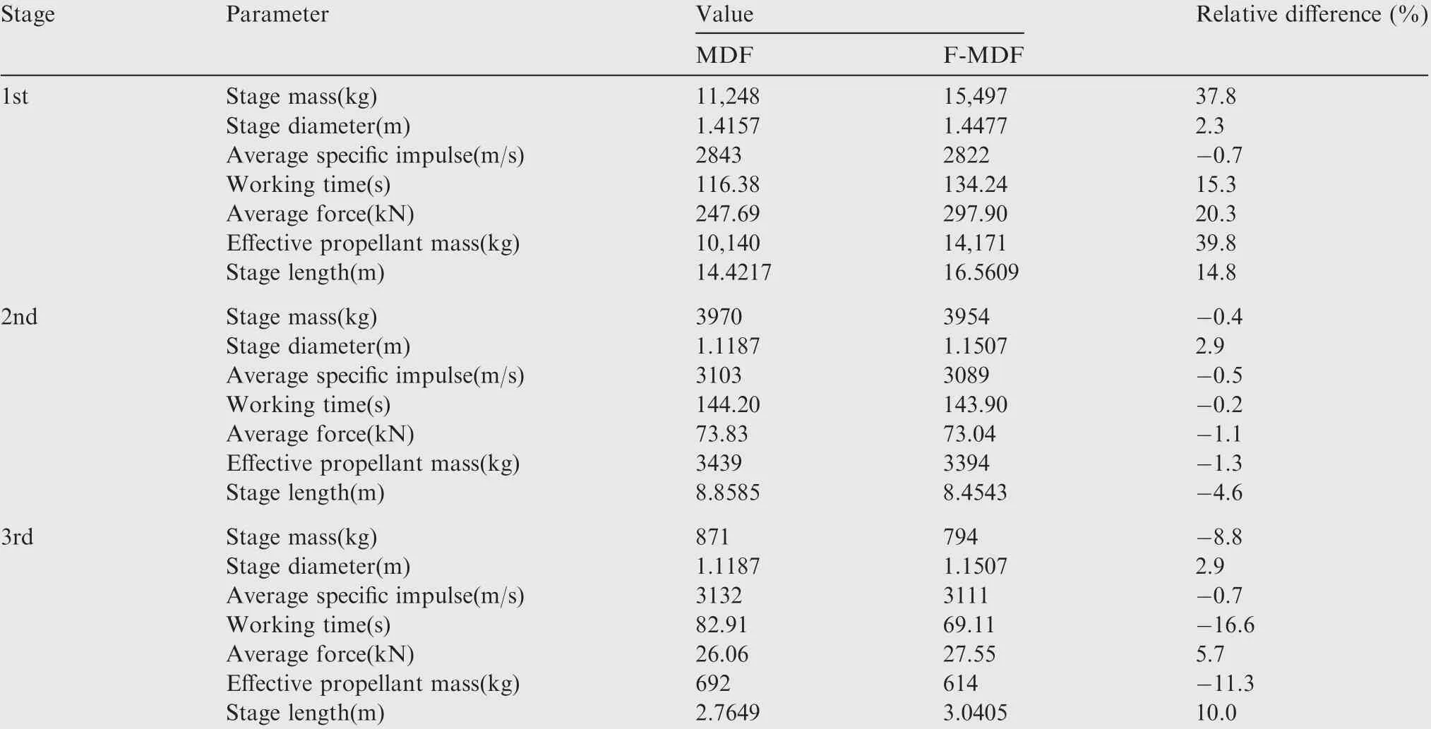
Table 11 Main performance of LV stages.

Table 12 Results of trajectory in STV phase.
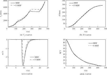
Fig. 10 Trajectory performance of MDF and F-MDF methods.
On the one hand,for remedying reduction of velocity increment in the 3rd stage caused by declination of effective propellant mass(-11.3%),at the 1st stage a significant improvement of velocity increment is needed to maintain the final velocity for scarifying the orbit index.On the other hand,the 1st stage HRM needs to improve its propulsion performance to resist uncertainty from velocity waste caused by air drag. Such change is helpful to improve reliability and robustness of the overall design.
The relative difference of average specific impulses of the three stages are respectively 0.7%,0.5%and 0.7%,which indicates that the optimal result of HRM propulsion performance is not significantly influenced by OFiand ε after the definition of grain type and propellant.
5.2. STV results
The main parameters of scheme trajectory of two LV designs are given in Table 12, where Vkis the velocity of shutdown point. Fig. 10 give the trajectory performance of two designs,where t is the flight time. The working time of both LV does not exceed 500 s (as shown in Fig. 10(a)) and each stage possesses reliable acceleration capability,while both Vkin Table 12 indicate that the designed LV can meet the required surround velocity at the payload release point. ΔH/Horband Eccorbin Table 12 prove that both designs can achieve predetermined height and the actual height H is less than 13 km away from mission height Horb.In actual engineering,ballistic parameters can be obtained in real time and autonomously modified through intelligent real-time control in order to ensure accuracy of the payload release orbit. The maximum of attack angle αmax1is not exceeding 3°. The structural instability caused by overlarge attack angle α is avoided,and a benign design dimension is left behind for attitude control system.The curves of tilt angle ϑkindicate that the LV powered by HRM possesses reliable performance,especially the 3rd stage HRM can access the orbit smoothly. The pitch angular velocity of the 3rd stage is small enough(as shown in Table 12)to modify attitude gently and enter the orbit accurately. Thus, HRM can be selected as the last stage of LV and can accurately arrive the predetermined orbit. Having the ability of force changing in wide range and long working time, HRM has great application prospects at the last stage for the small launch vehicle.
6. Conclusions
In this paper, a new approach based on the fuzzy theory and the MDF method has been proposed for UMDO, and is verified through a geometric programming problem.The rank correlation coefficient method and the quadratic RSM based on LHS are employed to appreciate the significant influencing factors of LV.A two-phase LV optimization method is proposed to reduce the calculation burden caused by trajectory calculation in each LV design scheme.
The design variables of grain geometric size (thickness and outer diameter)and burn parameter(regression rate coefficient and oxidizer mass flux exponent) in each stage directly decide HRM propulsion performance,and finally decide the LV conceptual design. With respect to both programming problem and LV design,the F-MDF method can obtain a more reliable and robust solution than the MDF method.However,a corresponding sacrifice of the objective function value is required for the improvement above. The increasing scale of the 1st stage HRM resists unreliability from estimated velocity waste and remedy shrink of the 3rd stage HRM. Both determinate and indeterminate LV designs possess a feasible scheme trajectory with good performance.
Compared with the MDF method,the calculation burden is significantly increased with the F-MDF method because of the fuzzy statistical experiment. Thus an effective approach needs to be introduced to solve the problem of computation costs in the UMDO. In addition, further study is needed to obtain appropriate velocity waste, which is too conservative to guarantee sufficient finial velocity.
Acknowledgement
This work was supported by National Natural Science Foundation of China (No. 51305014).
 CHINESE JOURNAL OF AERONAUTICS2020年5期
- CHINESE JOURNAL OF AERONAUTICS的其它文章
- Experimental of combustion instability in NTO/MMH impinging combustion chambers
- Three-line structured light vision system for non-cooperative satellites in proximity operations
- Remaining useful life prediction of aircraft lithium-ion batteries based on F-distribution particle filter and kernel smoothing algorithm
- Flow characteristics around airfoils near transonic buffet onset conditions
- Experimental investigation of flow and distortion mitigation by mechanical vortex generators in a coupled serpentine inlet-turbofan engine system
- An improved prediction model for corner stall in axial compressors with dihedral effect
