Study on effects of thickness on airfoil-stall at low Reynolds numbers by cusp-catastrophic model based on GA(W)-1 airfoil
Zhiping LI, Peng ZHANG, Tianyu PAN,*, Qiushi LI,d,Jian ZHANG
a National Key Laboratory of Science and Technology on Aero-Engine Aero-thermodynamics, Beihang University,Beijing 100083, China
b Collaborative Innovation Center for Advanced Aero-Engine, Beihang University, Beijing 100083, China
c School of Energy and Power Engineering, Beihang University, Beijing 100083, China
d Key Laboratory of Fluid and Power Machinery, Ministry of Education, Xihua University, Chengdu 610039, China
KEYWORDS Airfoil;Catastrophe theory;Low Reynolds number;Potential function;Thickness ratio
Abstract The phenomena of an airfoil stall present the behaviors of catastrophe and hysteresis at low Reynolds numbers. Numerical simulation results of two-dimensional airfoil GA(W)-1 show that the width of the hysteresis loop of airfoil stall will gradually decrease and even disappear with the decrease of thickness ratio. These nonlinear characteristics are in accordance with the topological features of the cusp catastrophic model. According to the topological invariant principle, a novel topological mapping method is developed to establish the mapping relationship between cusp catastrophic model and stall characteristics of the airfoil,then the effect of thickness ratio on airfoil stall is successfully described quantitatively by cusp catastrophic model. Further, based on the established topological mapping relationship,combined with the mean flow field of the airfoil stall,potential function approach of cusp catastrophic model is first introduced to interpret the catastrophe and hysteresis of the airfoil stall, and it is found that as the thickness ratio decreases, the system’s maximal potential energy gradually disappears,and the short separation bubble at the leading edge of the airfoil changes to long separation bubble,so the airfoil stall changes from a bistable system to a monostable system.
1. Introduction
In recent years, the aerodynamics of airfoil at low Reynolds numbers has obtained much attention as a result of the rise of unmanned aerial vehicles and micro air vehicles.It is found that airfoil stall at low Reynolds numbers has the characteristics of a catastrophe and hysteresis. Stall hysteresis was found on a square plate in the early 1930s.1Subsequently,researchers conducted a large number of studies on this phenomenon through experiments and computational simulations.Through studying the aerodynamic characteristics of Miley M06-13-128 and Lissaman 7769 airfoils at Reynolds numbers below about 3.0×10⁵, Mueller and Pohlen2,3found that stall hysteresis is common for thick airfoils,and the width of the hysteresis loop is influenced by the Reynolds number. The lift characteristics of the FX 63-137 airfoil4at low Reynolds numbers also showed the effect of Reynolds number on the size of the hysteresis loop. Mizoguchi et al.5studied the lift characteristics of wings with different thickness ratios at low Reynolds numbers and found the decrease and elimination of hysteresis with an increase in the thickness ratio. However, according to the research of Ananda6and Torres7et al., the hysteresis was shown to have an opposite dependency on the thickness ratio,and the stall hysteresis was not observed for thin airfoils. The research of Marchman et al.8,9also indicated that the width of the hysteresis loop is closely related to the aspect ratio, acoustic disturbance, and turbulence intensity. These researches show that the hysteresis of airfoil stall at low Reynolds numbers significantly depends on the operational environment and shape of the airfoil.
During the stall of an airfoil at low Reynolds numbers,catastrophe and hysteresis lead to discontinuous changes in the lift and drag characteristics of the airfoil, i.e., the aerodynamic performance may suddenly change when the angle of attack exceeds the critical value, which will bring great threat to the safety of the aircraft. So it’s crucial to understand the relationship between the nonlinear characteristics of the airfoil stall and the profile or the operational environment of the airfoil. However, strong nonlinearities such as discontinuous changes make it difficult to quantitatively describe the nonlinear characteristics of airfoil stall through traditional calculus method.
In mathematics, the hysteresis and catastrophe are associated with the concept of bifurcation10-15.Liu et al.16conducted bifurcation studies for the NACA 0012 airfoil at the Reynolds number of Re=1×10³, and found a saddle-node bifurcation of the system at the time of static stall. To understand the bifurcation phenomenon, Thom17first established the catastrophe theory, which has been applied broadly in the area of nonlinear dynamics to describe the effects of system parameters on the stability of a system.18-23The authors24recently investigated the effect of Reynolds number (based on the chord length) on the catastrophe and hysteresis during airfoil stall and developed an effective modeling method based on the catastrophe theory to describe the stall boundary of an airfoil at different Reynolds numbers. Noting that the thickness of airfoil also has an important influence on airfoil stall,based on the stall characteristics of GA(W)-1 acquired by numerical simulation, this paper also develops a model to describe the effect of thickness on the characteristics of airfoil stall and interpret the catastrophe and hysteresis of airfoil stall based on the catastrophe theory.
In this paper, first, the stall characteristics of airfoils with different thickness ratios are acquired through computational simulations and this provides the reference points for subsequent model description in Section 2. Then in Section 3, the cusp catastrophic model is introduced to relate the thickness ratio of the airfoil to airfoil stall.A topological transformation relationship is established between the cusp catastrophic model and the airfoil stall, then the effect of airfoil thickness on the characteristics of airfoil stall can be described by the cusp catastrophic model. Finally, the potential function approach of catastrophe theory is introduced to interpret the nonlinear characteristics of airfoil stall for different thickness ratios in Section 4, which is then followed by conclusions (Section 5).
2. Stall characteristics of airfoils with different thickness ratios
2.1. Airfoils with different thickness ratios
To explore the effects of airfoil thickness on airfoil stall at low Reynolds numbers,the stall characteristics of airfoils with different thickness ratios are first simulated computationally.Based on the GA(W)-1 airfoil, multiple airfoils with different thicknesses and similar profiles to the GA(W)-1 airfoil are obtained by scaling up or down the vertical dimensions of the GA(W)-1 airfoil,as shown in Fig.1(C is the chord length).For convenience, the relative thickness ratio is defined as

where Tcis the relative thickness ratio,Tris the thickness ratio,and Tr0is the thickness ratio of the GA(W)-1 airfoil.
2.2. Computational method
The airfoil stall at low Reynolds numbers is accompanied by a separation bubble and flow transition. Direct Numerical Simulations (DNS) can bring ideal precision to the study of transition phenomena.However,the extremely high computational cost still limits its applications in engineering applications.Compared with DNS, Large Eddy Simulations (LES) reduces the computational cost through partial simplification, but the cost of LES is still high for parameter studies and optimization. Therefore, Reynolds-Averaged Navier-Stokes (RANS)simulation seems to be the most suitable method for this work.The commercial software ICEM and FLUENT are used for mesh generation and computational simulation. Details of the computational method used to simulate the airfoil stall at low Reynolds numbers were introduced in Ref. 24 and is briefly summarized as follows.
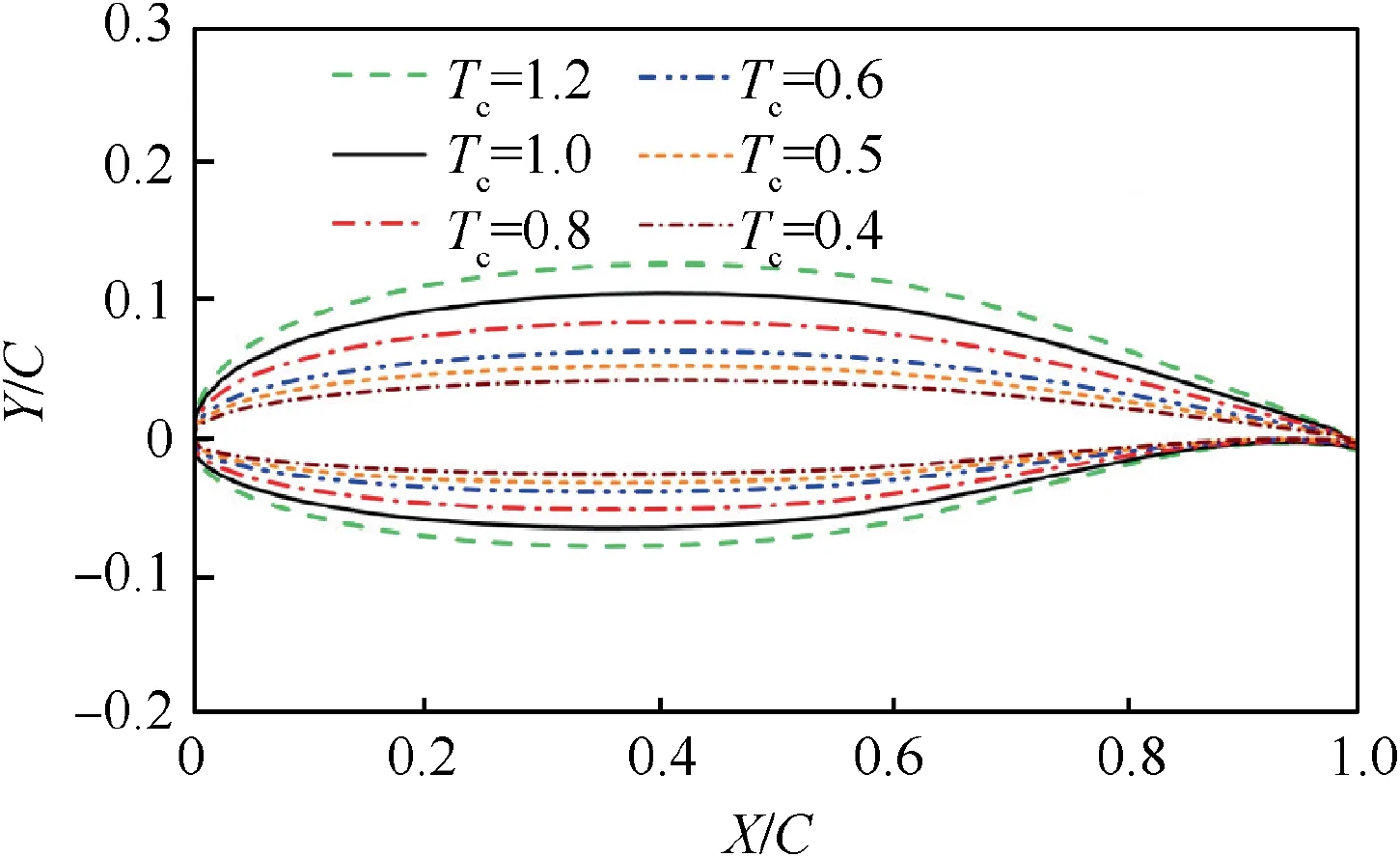
Fig.1 Airfoils with different thickness ratios based on profile of GA(W)-1 airfoil.
A C-type mesh is introduced to discrete the computational domain of the two-dimensional airfoil. In the computational domain, the upstream and downstream boundaries are placed 10 and 20 chord lengths from the airfoil,respectively.The partial mesh of the computational domains can be shown in Fig. 2. For all simulations, incompressible, two-dimensional,RANS equations, in conjunction with the γ-Reθmodel, are solved through the second-order upwind finite-volume technique, and a pressure-based double precision solver is applied with the SIMPLE scheme for pressure-velocity coupling. The γ-Reθmodel has been proven to be effective in predicting the lift characteristic of the airfoil and the onset of transition.25,26The domain inflow boundary is set to be uniform velocity inlet,and the no-slip condition is applied to the airfoil surface. The Reynolds number is defined by the free-stream velocity, the chord length of the airfoil, and the viscosity of the fluid. The free-stream turbulence intensity is less than 1%.
The resolution of the generated mesh is evaluated for three different levels of mesh refinement: fine (174600 nodes), medium (77400 nodes) and coarse (14960 nodes), and the medium mesh size is selected based on a comparison of the results with the experimental result,27as shown in Fig.3.The surface pressure of the airfoil (Tc=1) simulated using medium-size grids when α=12° (α is the angle of attack) is consistent with the experimental result and the onset of transition can be predicted accurately. Although some discrepancies in the lift and drag coefficients are found in Fig.4,both computational and experimental results have similar trends and the width of hysteresis loop predicted by the CFD simulation is close to the experimental result. Hence the computational method used in this paper is considered meeting the required accuracy of simulating the airfoil flow field at low Reynolds numbers. This method is also used to compute the lift characteristics of all the airfoils with different thickness ratios in this paper.
2.3. Results and discussions
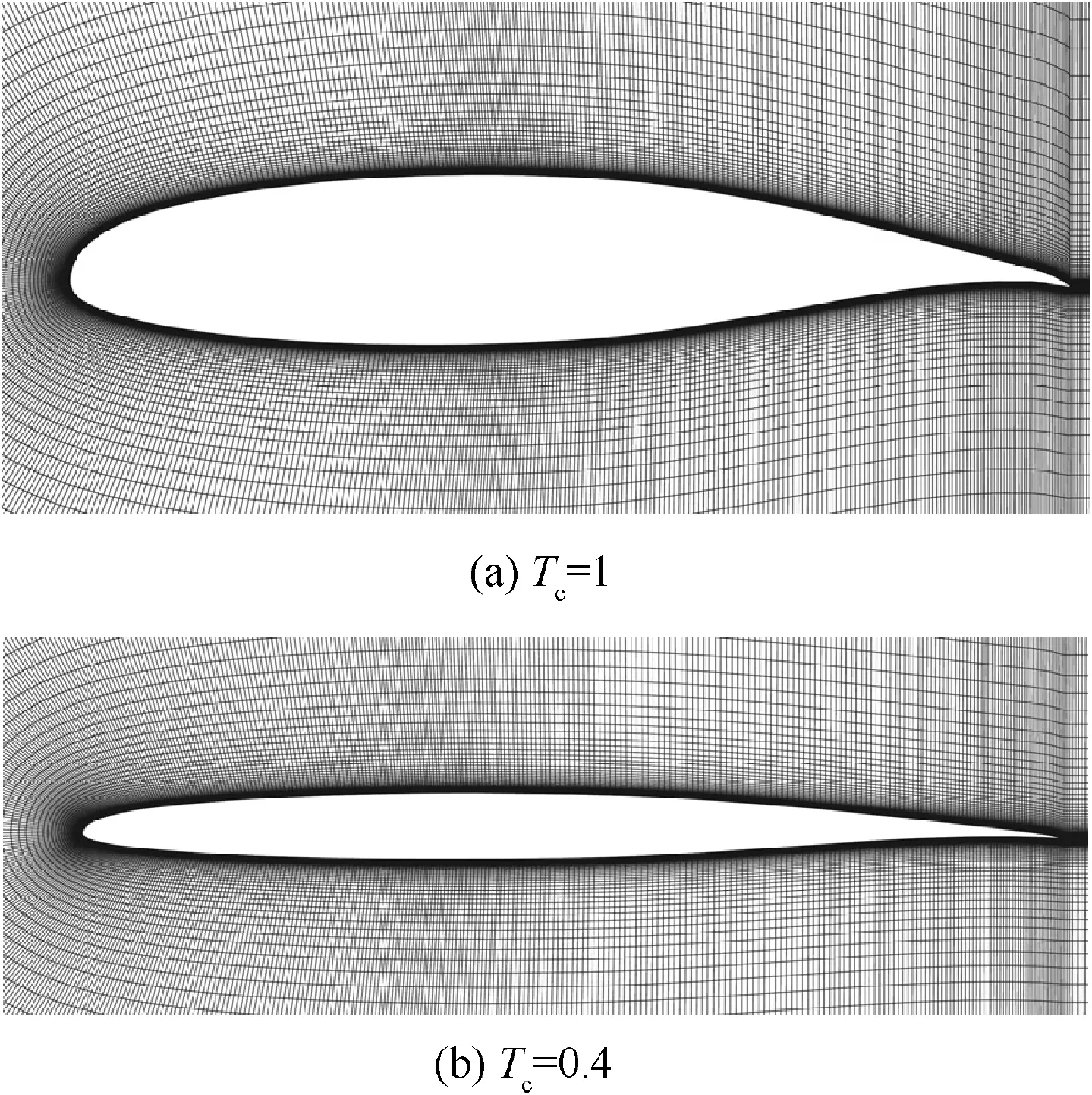
Fig. 2 Partial mesh of computational domains.
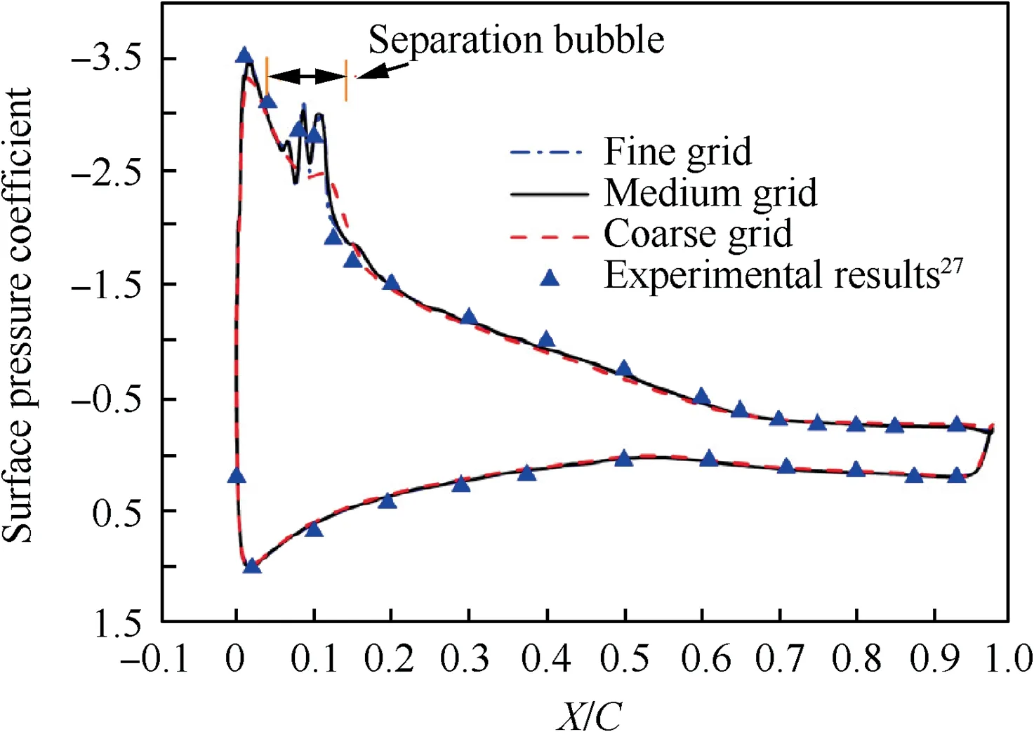
Fig. 3 Surface pressure distribution of airfoil (Tc =1) for α=12° and Re=1·6×105.
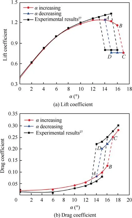
Fig. 4 Lift and drag coefficients of airfoil (Tc =1) at Re=1·6×105 and comparison with experimental results.
Previous research24has indicated that the airfoil stall exhibits a stronger hysteresis at Re=6×10⁵. Therefore, based on the computational method described above,the lift characteristics of airfoils with different thickness ratios are calculated at Re=6×10⁵to further study the effect of thickness on aerodynamic hysteresis.The results of the computational simulations are shown in Fig.5.The lift coefficient(CL)of the airfoil gradually decreases with a decrease of thickness ratio(Tc),and the peak lift coefficient is decreased by 46% as the relative thickness ratio varies from 1.2 to 0.4. When the thickness ratio is large, the airfoil stall shows the characteristics of hysteresis and catastrophe. With a decrease of the thickness ratio, the width of hysteresis loop gradually decreases until the relative thickness ratio reaches 0.4. When Tc=0·4, the lift coefficient changes continuously with the change of the angle of attack(α).As shown in Fig.5,projecting the stall and recovery points onto a control surface,which is consist of the relative thickness ratio and the angle of attack, it is found that the catastrophe boundary for all the thickness ratios falls onto two bifurcation lines called ‘‘bifurcation set”.
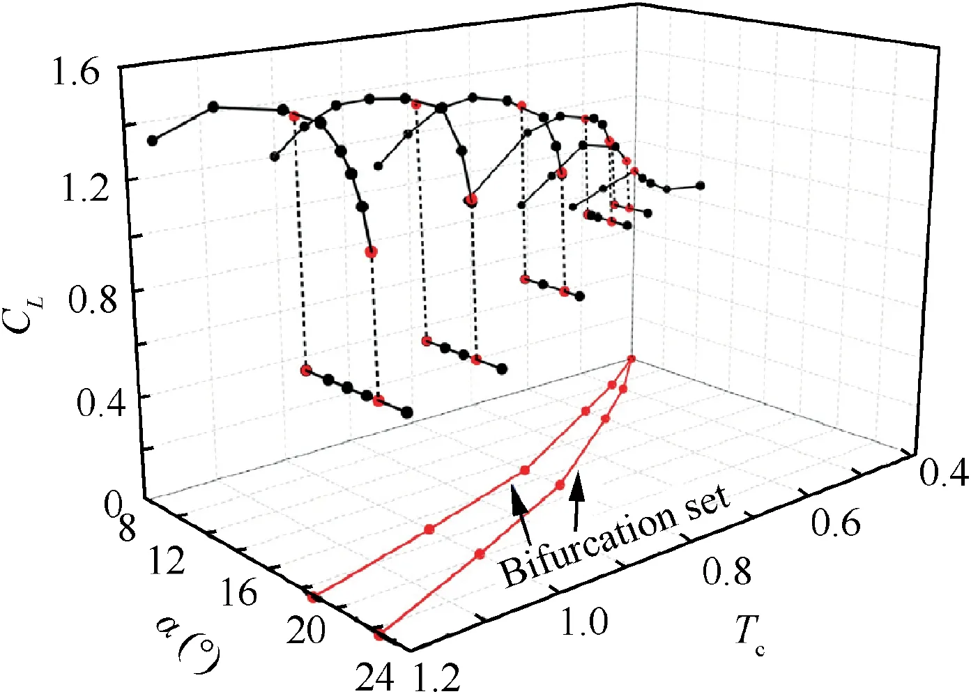
Fig. 5 Lift characteristics of airfoils with different thickness ratios at Re=6×10⁵.
Airfoil stall at low Reynolds numbers is a typical bistable system, i.e., stall state and normal working state are relatively stable and can be transformed into each other.The cusp catastrophe model of catastrophe theory is widely used to deal with related problems of the bistable system due to its simplicity and effectiveness.18-24The cusp catastrophic model described by the equilibrium surface is shown in Fig. 6, where the axes of the three-dimensional spatial topology consist of the control parameters u, v (horizontal) and state parameter x (vertical).The potential function equation and equilibrium surface equation are described by

and

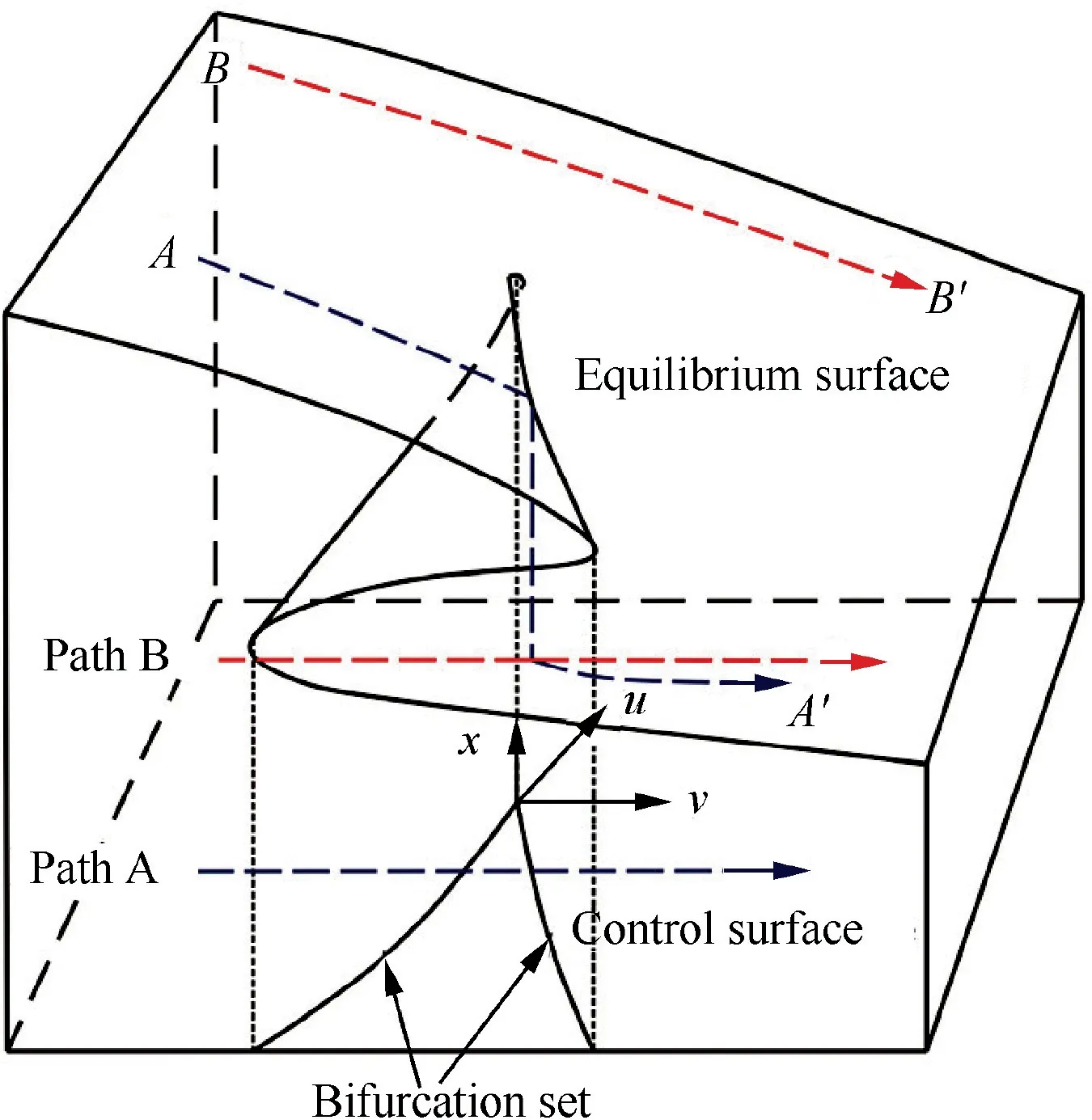
Fig. 6 Cusp catastrophic model.
where V(x) refers to the potential energy of the cusp catastrophic model. As shown in Fig. 6, the topological structure of the model shows the nonlinear characteristics of the model.When the control variable u is less than 0,as the other control variable v increases or decreases, the cusp catastrophic model shows the characteristics of catastrophe and hysteresis (such as Path A). As the value of u increases, the width of the hysteresis loop will gradually decrease until it finally disappears.When u is greater than 0, the model no longer demonstrates a catastrophe and hysteresis (such as Path B). The bifurcation set obtained by the projection of the model catastrophic points is found to be also two bifurcation lines.A more detailed introduction to the model can be found in the Refs.17-24Through analyzing the topological properties of the two systems, it can be found that the stall process (Fig. 5) of airfoils with different thickness ratios has similar spatial topology to the cusp catastrophe model (Fig. 6). According to the ‘‘topological invariant rules”,28the topological mapping relationship between two systems with similar spatial topology can be established through developing the topological mapping method. Thus, the cusp catastrophic model is introduced to describe the effect of thickness ratio on airfoil stall and interpret the physical mechanism of airfoil stall hysteresis.
3.Model description of thickness effects on airfoil stall based on catastrophe theory
3.1. Establishment of topological transformation relationship
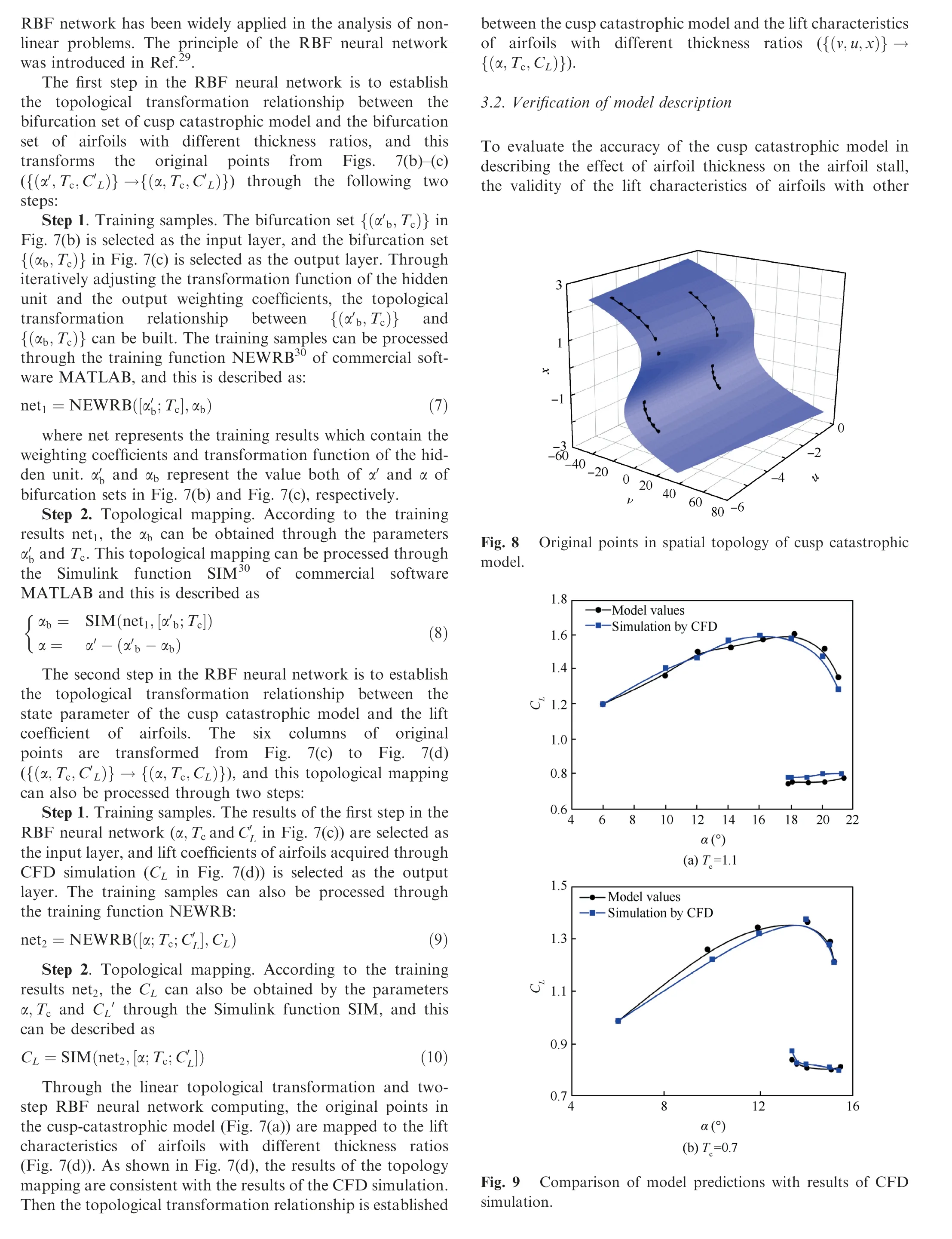
Stall and recovery points refer to the singular points under the theory of nonlinear dynamic systems.By studying the distribution rules of singular points, Whitney28presented the ‘‘topological invariant principle”, that is, topology mapping will not change the topological properties of singular points.According to the topological invariant principle, if the topological transformation relationship between the cusp catastrophic model (Fig. 6) and the stall characteristics of airfoils with different thickness ratios (Fig. 5) can be built (that is,{( v ,u,x)}→ {( α ,Tc,CL)}), then the effect of airfoil thickness on the characteristics of airfoil stall can be described by the cusp catastrophic model.The topological transformation relationship can be built through developing a novel effective topology mapping method. The topology mapping method mainly includes two parts: the linear topological transformation and two-step RBF (Radial Basis Function) neural network.
3.1.1. Linear topological transformation
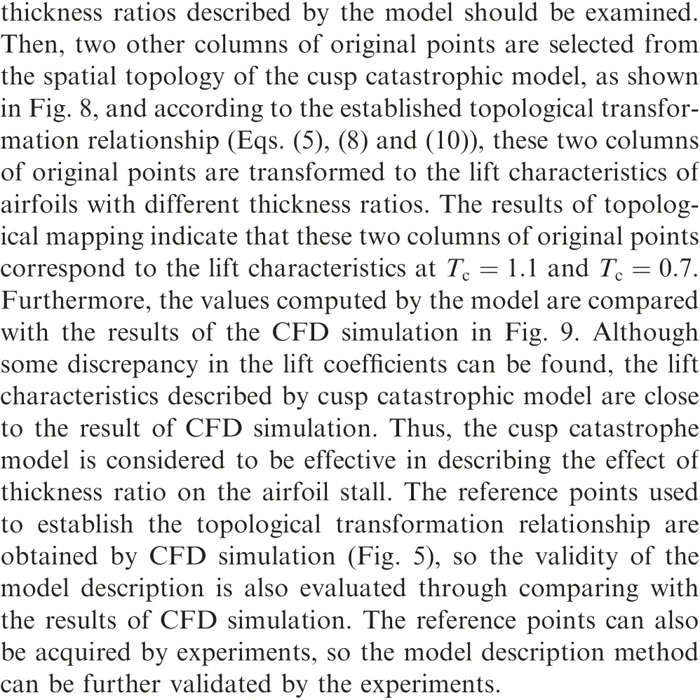
Before the linear topological transformation, six columns of points selected from the spatial topology of the cusp catastrophic model are considered as the original points, as shown in Fig. 7(a). These six columns of original points are selected according to the following rule:
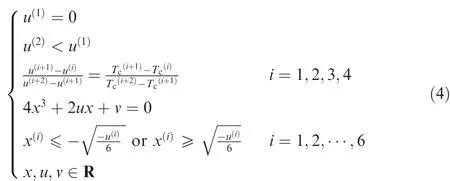
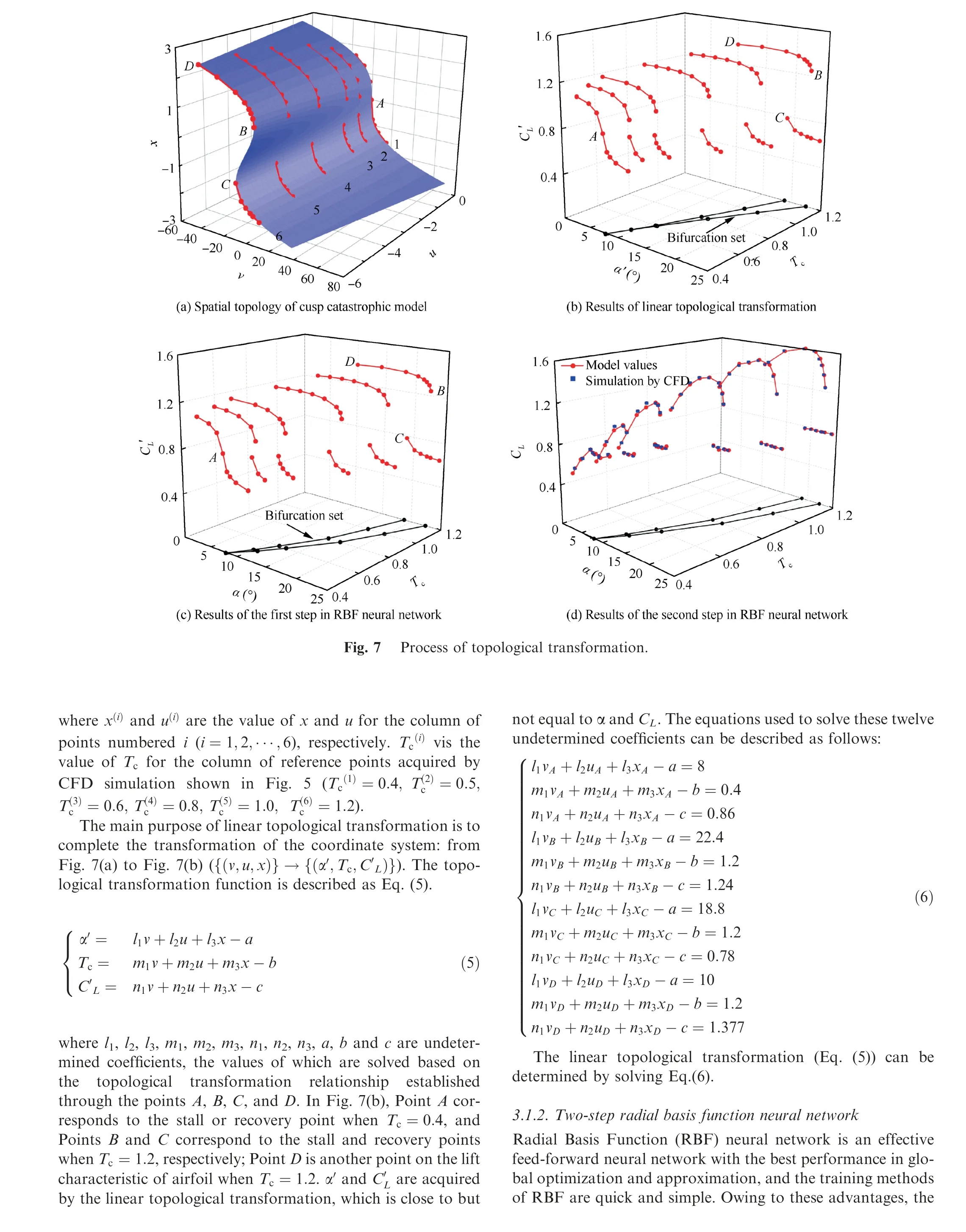
4. Physical mechanism analysis of airfoil stall hysteresis based on catastrophe theory
Based on the stall characteristics of GA(W)-1 and its affined family acquired by numerical simulation, a model method is developed to describe the effects of thickness on the stall of these airfoils. Based on the topological invariant principle,combined with the mean flow field of the airfoil stall,the cusp catastrophic model can also be used to interpret the catastrophe and hysteresis of the stall for these airfoils.
4.1. Hysteresis interpretation of airfoil stall based on potential function approach
The catastrophe theory reveals the law that the potential energy of the system changes with the control variables by constructing different potential functions, which further determines the stability of the system. For GA(W)-1 airfoil and its affined family, through the topology mapping method developed in Section 3, the topological transformation relationship between the cusp catastrophic model and the airfoil stall has been established. Thus, the potential function approach of cusp catastrophic model is introduced to interpret the catastrophe and hysteresis of the stall for these airfoils.
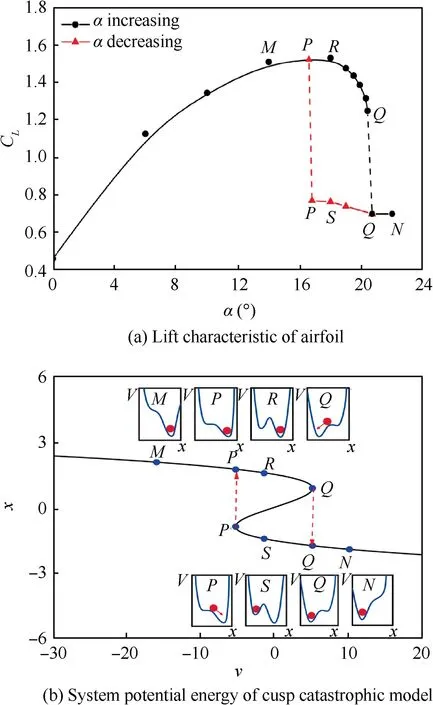
Fig. 10 Potential function approach interpreting hysteresis of airfoil stall (Tc =1·0, u=-4·5).
According to the topological transformation relationship,Tc=1·0 corresponds to α, and the hysteresis loop consists of line M-P-R-Q and line N-Q-S-P in Fig. 10(a) can be mapped to Fig.10(b).According to potential function equation of cusp catastrophic model (Eq.(2)), the potential energy (V) of cusp catastrophic model at different state points can be calculated,as shown in Fig. 10(b)(the ball represents the state of the system),which also reflects the variation of the potential energy of the airfoil stall process. When the angle of attack is small, the state point corresponds to Point M,and only minimum potential energy can be found in the system,so the airfoil stays in the normal-working state and will not switch to the stall state despite a disturbance. As the angle of attack increases and when the state point reaches Point R, the system generates another minimal potential energy(two different working states at the same angle of attack). Due to the barrier (a maximal potential energy point) between the two states, the airfoil will always be in the normal working condition under the minor disturbance, but it will transform from the normal working condition to the stall state due to large disturbances. When the state point moves to Point Q,the barrier has gradually disappeared,so even a small perturbation may cause the airfoil to transform from the normal-working state to the stall state because of a positive feedback effect. At this time, if the angle of attack decreases and the state point reaches S, the other minimum potential energy appears again.For the same reason,the airfoil will remain in the stall state under small disturbances and switch to the normal-working state due to large disturbances. As the angle of attack is further decreased, the barrier between the two states will disappear again, and the airfoil will recover to the normal operating state due to minor disturbances because of a positive feedback effect,as shown by Point P.
According to the topological transformation relationship,Tc=0·4 corresponds to u=0, and the characteristic curve of the airfoil (line M-Q-N) in Fig. 11(a) can be mapped to Fig. 11(b). According to the potential function equation, the potential energy (V) of cusp catastrophic model at different state points can also be calculated, as shown in Fig. 11(b).As the angle of attack increases (from M to N), the system always has only one minimum potential energy. Therefore,the system can maintain its original state under all disturbances.The whole process does not show the salient characteristics of catastrophe and hysteresis.
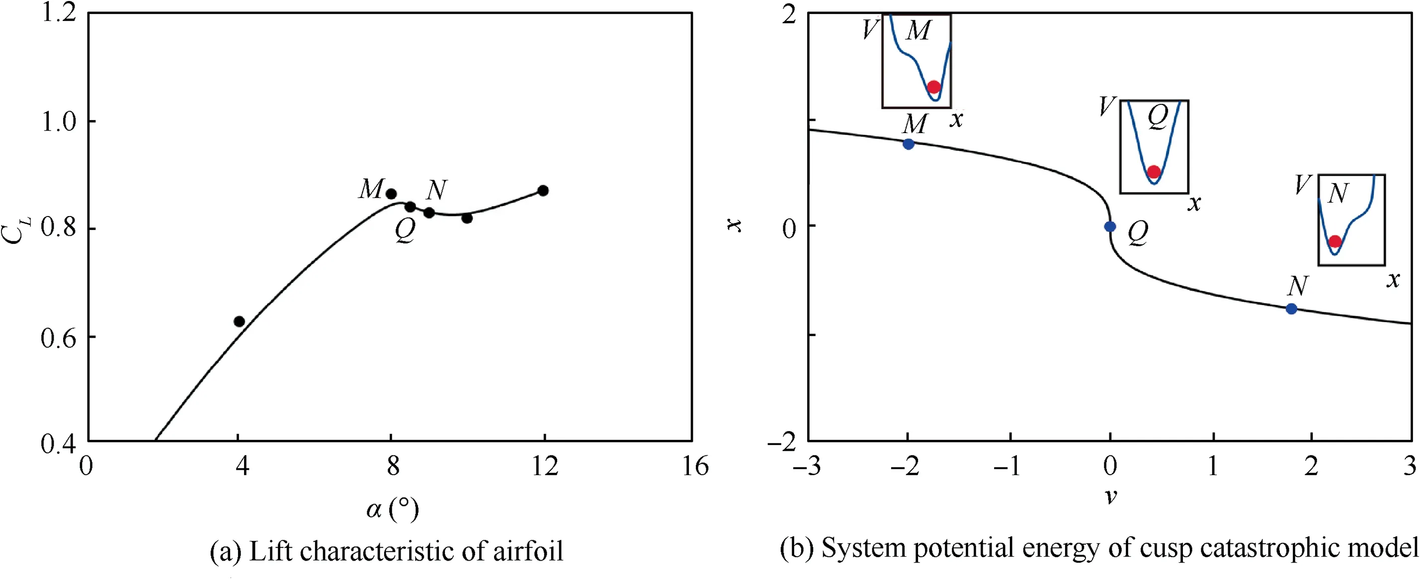
Fig. 11 Potential function approach interpreting hysteresis of airfoil stall (Tc =0·4, u=0).
According to the above analysis,the presence of a maximal potential energy point allows the airfoil to remain relatively stable in two states. It is difficult for an airfoil to transition from one state to another without sufficient energy, and this leads to stall hysteresis. When the system is at the maximal potential energy point, the airfoil quickly changes from one state to another under the influence of positive feedback, and this leads to stall catastrophe.As the thickness ratio decreases,the maximal potential energy point gradually disappears and the airfoil stall changes from a bistable system to a monostable system.
4.2. Streamlines of mean flow fields at various angles of attack(Tc =1 and Tc =0·4)
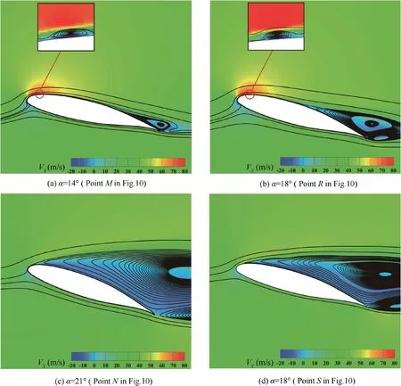
Fig. 12 VX distributions and streamlines of mean flow field of airfoil for Tc =1.
To further study the physical mechanism of airfoil stall hysteresis, the near-stall streamlines of the mean flow field of airfoils with different thickness ratios are analyzed.Fig.12 shows the stall process of the thick airfoil(Tc=1),VXis the velocity in X direction. When α=14°, corresponds to Point M in Fig.10,a short separation bubble is found at the leading edge of the airfoil and trailing edge separation can also be observed.As α increases from 14°to 18°(Point R in Fig.10),The size of the leading-edge separation bubble is gradually reduced, and the laminar boundary layer is tripped to become turbulent.The trailing edge separation on the upper surface of airfoil gradually develops toward the leading edge of the airfoil.When the angle of attack increases to a critical value (Point Q in Fig. 10), before the trailing-edge separation reaches the separation bubble, the bubble bursts and this leads to separation on the entire upper surface of the airfoil(α=21°,Point N in Fig.10). At this time,when α decreases from this value,the flow remains separation on the entire upper surface (Fig. 12(d)) until α reaches another critical value. As the angle of attack is further decreased, the airfoil will exit the stall state,and the separation bubble will be found again at the leading edge of the airfoil.

Fig. 13 VX distributions and streamlines of mean flow field of airfoil for Tc =0·4.
Fig.13 shows the stall process of the thin airfoil(Tc=0·4).When α=8°, corresponds to Point M in Fig. 11, a separation bubble is found at the leading edge of the airfoil and trailingedge separation is not observed. As α changes from 8°to 8·5°(Point Q in Fig. 11), the reattachment point of bubble develops from upstream to downstream and the size of the separation bubble increases as the angle of attack increases. Such a separation bubble can be categorized as a long bubble. As the angle of attack further increases, the separated flow will no longer reattach and leading-edge separation can be found(α=9°, Point N in Fig. 11). Reflecting on the overall characteristics, the lift coefficient progressively changes as the angle of attack increases or decreases. Thus, the difference in the development of separation leads to the difference between the stall characteristics of thick and thin airfoils.
Combined with potential function method and flow field analysis, it can be seen that the short separation bubble at the leading edge of the airfoil causes the system to have a maximal potential energy point,which allows the airfoil to remain relatively stable in both states, and on the other hand, it can also cause the airfoil to quickly transform from one state to another state as a positive feedback. As the thickness ratio decreases,the short separation bubble changes to long separation bubble and the airfoil stall changes from a bistable system to a monostable system.
The static stall at low Reynolds numbers is studied from the viewpoint of nonlinear dynamics. The model method presented in this paper is based on the stall characteristics of GA(W)-1 and its affined family acquired by numerical simulation, so it is not appropriate to apply it to all kinds of airfoils due to the complexity of the airfoil stall at low Reynolds number. The method presented in this paper is considered to be effective for the GA(w)-1 airfoil and similar airfoils, such as the NACA00 series.Through further research,the method also has the potential to be applied to other shapes of airfoils.
5. Conclusions
This paper focuses on the effect of airfoil thickness on the characteristics of the airfoil stall at low Reynolds numbers.Taking the GA(W)-1 airfoil as the research object, the lift characteristics of airfoils with different thickness ratios are acquired through computational simulations. Based on topological invariant rules, the cusp catastrophic model is introduced to describe the effect of thickness ratio on airfoil stall and interpret the physical mechanism of airfoil stall hysteresis.Three conclusions are deduced as follows.
(1) The whole process of airfoil stall at low Reynolds numbers displays salient characteristics of catastrophe and hysteresis. The width of the hysteresis loop is influenced by the thickness ratio,an important design parameter of the airfoil.For GA(W)-1 airfoil and its affined family,at a certain Reynolds number, the width of the hysteresis loop will decrease as the thickness ratio decreases, and when the thickness ratio is smaller than the critical value, the process of airfoil stall will no longer show catastrophe and hysteresis.
(2) Based on topological invariant rules, the topological transformation relationship between the cusp catastrophic model and the airfoil stall is established through a developed topological mapping method, and the stall characteristics of airfoils with different thickness ratios can be described quantitatively by the cusp catastrophic model.This modeling method is examined by comparing the model results with the simulated values.
(3) Combined with the mean flow field of the airfoil stall,the potential function approach of cusp catastrophic model is introduced to interpret the nonlinear characteristics of the stall for GA(W)-1 airfoil. The short separation bubble at the leading edge of the airfoil causes the system to have a maximal potential energy point,which further leads to the catastrophe and hysteresis of airfoil stall. As the thickness ratio decreases, the short separation bubble changes to long separation bubble and the airfoil stall changes from a bistable system to a monostable system.
Acknowledgements
This research was supported by the National Natural Science Foundation of China (Nos. 51676006, 51636001 and 51706008), Aeronautics Power Foundation of China(No.6141B090315), and National Science and Technology Major Project, China (No. 2017-Ⅱ-0005-0018).
 CHINESE JOURNAL OF AERONAUTICS2020年5期
- CHINESE JOURNAL OF AERONAUTICS的其它文章
- Experimental of combustion instability in NTO/MMH impinging combustion chambers
- Three-line structured light vision system for non-cooperative satellites in proximity operations
- Remaining useful life prediction of aircraft lithium-ion batteries based on F-distribution particle filter and kernel smoothing algorithm
- Flow characteristics around airfoils near transonic buffet onset conditions
- Experimental investigation of flow and distortion mitigation by mechanical vortex generators in a coupled serpentine inlet-turbofan engine system
- An improved prediction model for corner stall in axial compressors with dihedral effect
