Dynamics modeling and pressure control of composites tape winding system based on LQSMC
Qi HONG, Yaoyao SHI, Danni LU
The Key Laboratory of Contemporary Design and Integrated Manufacturing Technology Ministry of Education,Northwestern Polytechnical University, Xi’an 710072, China
KEYWORDS Composites tape winding;Dynamics modeling;Kalman filter;LQSMC;Pressure control
Abstract Pressure fluctuations during the composite fiber winding process seriously affect the product’s compactness strength, fatigue resistance, stress uniformity, and resin content. The accuracy of pressure control systems is affected by nonlinear disturbances,such as friction,parameter perturbation,and measurement noise.A robust control algorithm based on linear quadratic optimal control and sliding mode control (LQSMC) is proposed to overcome these problems. The method is based on the system state space expression and linear quadratic optimal control. The state space model of the system is improved by using a Kalman filter and control input for state estimation,and a new sliding surface equation is defined.The ameliorated control algorithm exhibits good performance and can effectively suppress sliding mode control (SMC) chattering. Simulation and experimental results show that LQSMC offers high control precision, much stronger antiinterference, and robustness, which can effectively improve the positioning and tracking accuracy of a pressure control system compared with linear quadratic optimal control (LQC). The winding pressure control precision is improved by 45%to 50%.The results show that the porosity of composite fiber tape winding products decreased thanks to our method.
1. Introduction
Composite materials are different from traditional materials.They are formed from two or more materials under certain conditions. Composite materials have advantages of high specific strength, low weight, high specific stiffness, fatigue resistance, and flexibility in design.1,2Therefore, composite materials have been widely used in high speed rail,new energy materials, aerospace vehicles, launch vehicles, yachts, and in other industries, and they were also considered to be the best choice for design of future aerospace structures.3,4Fiber tape winding molding is one common method used in the composite molding process.Many prior studied have focused on optimizing the process parameters used for composite winding forming.5-7The effects of pressure, tension, temperature, and winding speed on the product performance were discussed in prior publications.8-14Winding pressure is one of the primary factors affecting the quality of composite products.Applying a certain value of pressure could remove bubbles from the wound layer, improving the compactness and reducing the porosity of the product.15,16During a practical manufacturing process, the pressure control of our winding machine equipment is unstable, which reduces the performance of our composite products.
From the perspective of control, winding pressure control systems for composite materials are complex, uncertain, and nonlinear systems, which poses some challenges for feedback controllers and system modeling. Some scholars, proposed corresponding control strategies for solving this problem. In literature,17a pressure control system based on a pneumatic proportional valve for composite belt placement molding was designed. In literature,18winding pressure was regulated using a proportional valve. A sliding mode controller was designed to compensate nonlinear disturbances in the valve port flow and gas leakage in a pneumatic system, allowing the force to be controlled with a pneumatic servo valve.19In literature,20a fuzzy controller was used to control a mechanical arm with a high speed pneumatic on-off valve. In literature,21a fuzzy sliding mode variable structure controller was used to provide constant pressure control based on a suspension system with a pneumatic servo valve. In literature,22an adaptive sliding mode control algorithm was adopted to realize the precise control of the A-axis for high-efficiency and powerful compound milling machine.In literature,23an adaptive terminal sliding mode finite time control method was proposed to improving the robustness of spacecraft system and avoid the chattering of the controller.
Fuzzy control and sliding mode control are always used to eliminate the negative effects of nonlinear factors in pneumatic systems.This paper analyzes the dynamic and static characteristics of a pressure control system for a large-scale NC fiber tape winding machine. A nonlinear dynamic model of the winding pressure pneumatic control system is also presented.A robust control algorithm based on linear quadratic optimal control and sliding mode control is proposed in this paper.The method is based on the system state space expression and linear quadratic optimal control.By introducing the state estimation based on control input and Kalman filter, a new sliding surface equation is defined and the system state space model is improved. The proposed control algorithm provides good performance and can effectively suppress chattering in SMC.The simulation results agree well with the experimental results,indicating the reliability of the algorithm and applicability of the mathematical model.
2. Mathematical modeling of a pneumatic winding pressure control system
The pneumatic winding pressure control system is includes a proportional pressure reduction valve, electromagnetic valve,air compressor, power cylinder, pressure sensor, A/D and D/A converters, industrial control machine, servo driver, and power amplifier. Fig. 1 shows the structure of the pneumatic pressure control system. The proportional pressure reducing valve converts the control signal into a pressure signal and controls piston motion in real time by controlling the flow of gas into the cylinder. A precise mathematical model for the pressure control system can be developed for this process.The industrial computer is the core of the pressure control system, which is used to collect, process, and send the winding pressure feedback signal. The computer also provides realtime analysis and processing.
The theoretical output thrust of piston can be derived from Fig. 2 as follows:

where Ftis thrust of piston,P1,A1,P2,and A2are the pressure and piston area in the left and right chambers, respectively.
In practice,the actual output thrust force on the piston rod is smaller than the theoretical thrust due to mechanical frictional on the cylinder wall,the piston seal ring,and the inertial force of the moving cylinder. If friction is taken into account.Newton’s second law can be used to derive the following equation of motion for the cylinder:

where Rfis the sum of all frictional forces in the cylinder assembly, m is the mass of the moving parts, b is the viscous damping coefficient of the piston and load,and xpis the piston displacement.
The mass flow of gas into the chamber can be written as follows:

where qmis the gas mass flow rate,ρ is the gas density,and V1and m1are the volume and mass of the gas in the chamber,respectively.
From the foregoing assumptions, the equation of state for ideal gas can be expressed as follows:

The total derivative of Eq. (4) is

where k is the gas adiabatic exponent, T is absolute temperature, R is the universal constant of gas.
Eq. (6) can be derived from Eqs. (3) and (5):

The following can be obtained by further derivation and applying a Laplace transform:

The nonlinear mass flow equation of gas through a one dimensional orifice can be expressed as follows:

where xvis displacement of the proportional valve spool, w is the gradient of the proportional valve orifice area,kvis the displacement coefficient of proportional valve spool, A3is the pressure area of the cone valve on the valve seat, and Piand Poare input pressure and output pressure at the reduction valve, respectively.
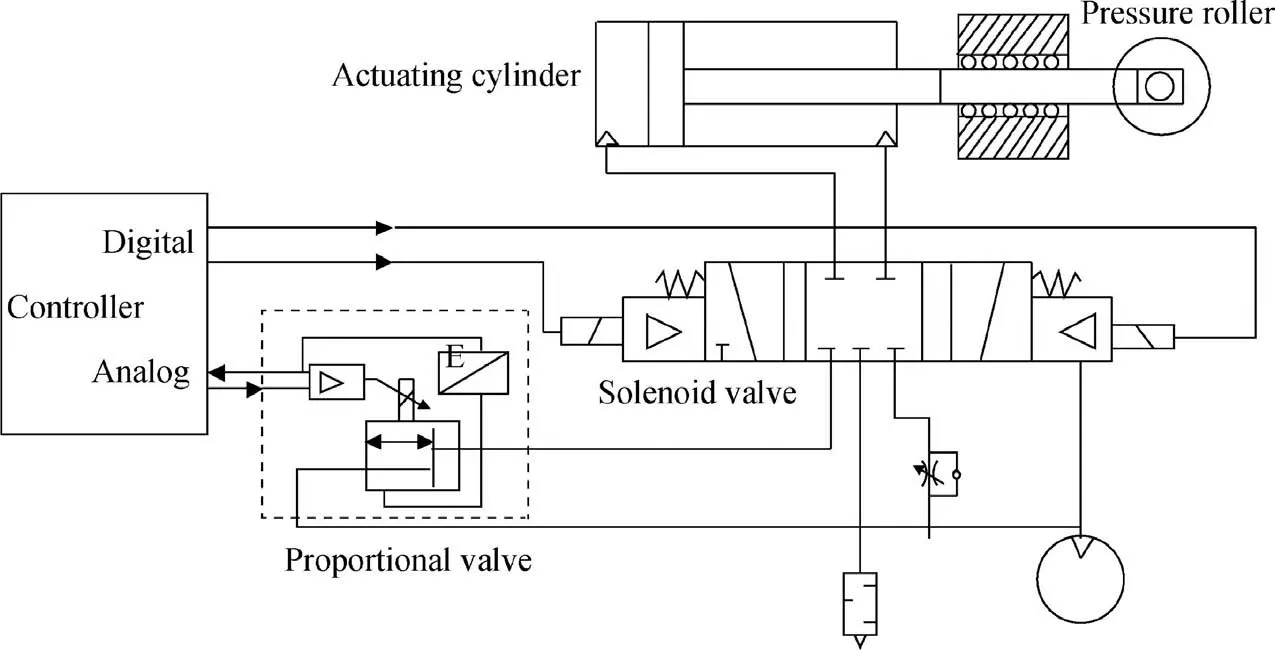
Fig. 1 Schematic of pneumatic pressure control system.

Fig. 2 Sketch map of pneumatic cylinder thrust.
Through further derivation and applying specific parameter values of pressure control system shown in Table 1, the transfer function for the pressure control system can be expressed as follows:

3.Design of the SMC based on linear quadratic optimal control
3.1. Linear quadratic optimal control
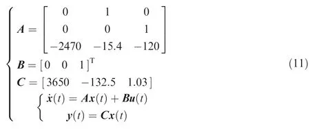
where A is the system matrix, B is the input matrix, C is the output matrix,x(t)∈Rnis the system state,u(t)∈Rmis the control input, and y(t) ∈Rris the control output.
The optimal feedback gain of the quadratic objective function and the system state space can be obtained through the linear quadratic regulator.One can obtain the following mathematical model that is closer to the real system by adding an external interference to improve the system state space equation:

where W is the process noise, G is a process noise coefficient matrix,and V is the measurement noise.The objective function can be written as follows:25

where R ∈Rm×mRm×mand Q ∈Rn×nRn×nare symmetric positive definite weight matrices
Ricotta’s matrix algebraic equation can be expressed as follows:
After looking at her he said, in a tone that might have struck terror into the boldest heart, though he did not seem to be angry: Good-evening, old man

where S is the only solution of Ricotta’s matrix algebraic equation.
A feedback controller based on a linear quadratic form in Eq.(15)can be used to solve the minimum value of the objective function.

Table 1 Parameter values and description of pressure control system.

where K is feedback controller gain.26
3.2. SMC based on linear quadratic optimal control
State feedback control requires feedback from all state variables. However, not all system state variables in Eq. (13) can be measured.Therefore,the value of a state variable in the system can be estimated using a Kalman filter. The state variable expression can be written as follows:

where L is the Kalman filter gain and ^x(t)is the state estimate of x(t).
In traditional sliding mode control, parametric perturbations and small external disturbances will generate chattering.27Reducing the effects of uncertainties and external disturbances on the control performance of the system requires large switching gain. The improved algorithm estimates the state variable value of the system using a Kalman filter.In this method, the difference between the actual system output and the nominal model output caused by backlash,parametric perturbation,friction,and noise is equivalent to the control input.The Kalman filter smooths the control signal and reduces chatter to some extent. Introducing equivalent compensation to suppress interference can effectively suppress chattering in sliding mode control.
The control input u(t)is introduced to construct a new state variable. The new state variables and control inputs can be defined as follows:

The state space equation can be written as follows:
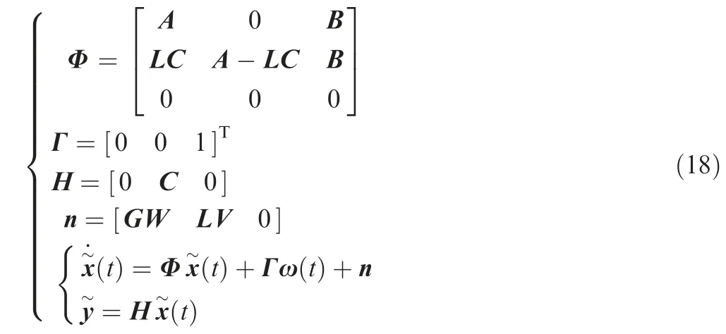
A robust control algorithm based on sliding mode control and linear quadratic optimal control is proposed to improve the system state space model.

From Eqs. (18) and (19), the following equation for the sliding surface can be defined:

The objective function in Eq.(21)can be minimized using a feedback controller based on a linear quadratic form:


According to the reaching condition for sliding mode control σ(˙x)˙σ(x~)<0, a feedback controller based on a linear quadratic form can be obtained as follows:

where μ is the switching gain and sat(·) is the saturation function.
4. Simulation analysis
The mathematical model of the pressure control system is used to verify the performance of the designed control algorithm.LQC and LQSMC are used to simulate position and tracking control of the output pressure. A step signal (r1(t)=1500 N)is used for positioning control and a sinusoidal signal (r2(t)=1500sin(πt) N) is used for tracking control.
First, process and measurement noise with 10 N amplitude were applied to the system to verify the anti-jamming performance of the control algorithm. Step responses based on LQC and LQSMC in the presence of noise interference are shown in Fig. 3(a) and (b), and the sinusoidal tracking responses are shown in Fig. 4(a) and (b). Second, parameter perturbations were applied to the system to verify the robustness of the control algorithm.The parameter perturbations are Δi=10-3sin(πt)i, (i=A, B, C), and the resulting step responses based on LQC and LQSMC are shown in Fig. 5(a) and (b), respectively. The corresponding sinusoidal tracking responses are shown in Fig. 6(a) and (b), respectively. A comparison of simulation control errors are shown in Table 2.
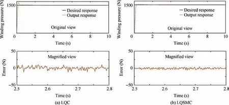
Fig. 3 Step response under an external disturbance.
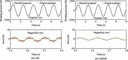
Fig. 4 Sinusoidal response under an external disturbance.
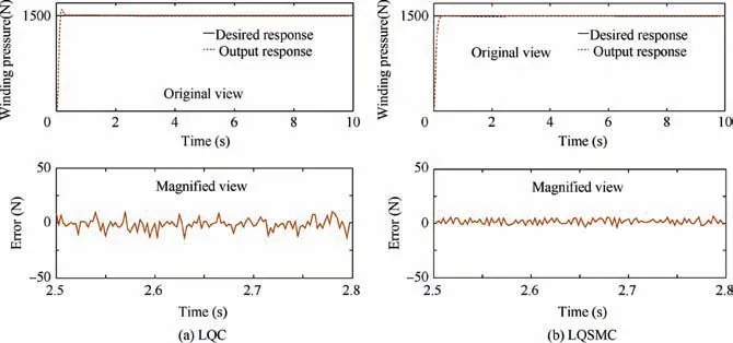
Fig. 5 Step response under parameter perturbations.
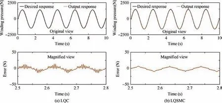
Fig. 6 Sinusoidal response under external disturbance.

Table 2 Comparison of simulation control errors.
Table 2 shows that the step response control error is 12.83 N using LQC due to the external disturbance.The corresponding step response control error is 5.86 N using LQSMC.the system control error is more complex. In literature,24experiments were required to further verify the performance of the control algorithm. The stability of the LQC algorithm was proven using lyapunov stability theory. In literature,28the stability of SMC was analyzed. The simulation results show that the LQSMC algorithm improves the control accuracy and provides good stability.
5. Experimental verification
Compared with the LQC algorithm, the pressure control precision is enhanced by 55.7%. The sinusoidal response control error is 11.59 N with LQC and the control error is 5.24 N with LQSMC. The pressure control precision is enhanced by 54.8%. The step response control error is 13.01 N due to parameter perturbations with LQC and the step response control error is 6.36 N with LQSMC.Compared to the LQC algorithm, the pressure control precision is enhanced by 51.1%.The sinusoidal response control error is 12.17 N with LQC and 5.73 N with LQSMC. The pressure control precision is enhanced by 52.9%.
An actual system is affected by various external disturbances and parameter perturbations, and their influence on An advantech IPC-620-L was used as the controller carrier in our experiments. The LQC and LQSMC control programs were written in C++. The control programs include digital and analog signal conversion, sampling, and pressure sensor measurement functionality. An advantech PCL732 digital I/O card, PCL820L data acquisition card, and PCL728 analog output card were used to convert, acquire, and export data.Lab windows/CVI was used to display, analyze, and process the collected data.The IPC sends instruction signals to control the pneumatic servo system, providing real-time control.
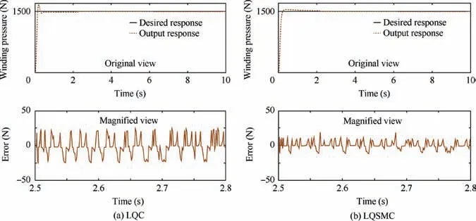
Fig. 7 Step response results.
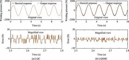
Fig. 8 Sinusoidal response results.

Table 3 Experimental control error comparison.
The experimental process involves winding composite tape material in parallel on a round bar and measuring the change in winding pressure when different control algorithms were used.An SD#1 winding machine was used as the experimental platform.The SD#1 winding machine could rotate the spindle at a constant speed.The maximum linear speed of spindle was 24 m/min, the rotation speed ranged from 0 to 60 r/min, the feed resolution was 0.001 mm,and the maximum feed per revolution was 125 mm.
First, step(Fsv1)and sinusoidal(Fsv2)response signals with amplitudes of 1500 N were used to verify the accuracy of the two different control algorithms. The experimental results from step and sinusoidal responses based on LQC and LQSMC control are shown in Figs. 7 and 8.
The experimental step response results are shown in Table 3.Under the condition that the rise and adjustment times are similar, the steady-state error in the step response with LQSMC is reduced by 50.6%compared to LQC.For the sinusoidal response,the steady-state error with LQSMC is reduced by 51.4% compared to LQC. It can be seen that the experimental results and simulation results are consistent.
The effectiveness and feasibility of the proposed LQSMC scheme was verified further. Porosity changes were examined with different pressure control strategies. The spindle was wound at a constant linear speed, the winding speed was set to 16 m/min, the tension was set to 1200 N, the pressure was set to 1000 N, and the hot air temperature was set to 80°C.The prepreg winding process and curing process for composite products were examined in our experiments. A circular steel mandrel with an external diameter of 150 mm was used in the winding process. In Fig. 9, the experimental pieces were made with layered superimposed circular winding, and a high precision deviation correction control system was used to ensure winding accuracy.The heating rate and curing pressure were 2.5°C/min and 0.15 MPa, respectively. The product was allowed to cure for 150 min at 150°C. The experiment was conducted at ambient temperature (20±2) °C and relative humidity of(25±2)%. A carbon fiber/epoxy resin composite prepreg tape produced by GLOWAY composite material Co.,Ltd.(Weihai,China)was used in the experiment.Carbon fiber T-300 was used as a reinforcing material in the prepreg tape.The matrix was epoxy resin YH-69, and the prepreg tape had a woven structure with a braided angle 0°/90°.The volume fraction of fiber was (56±2)%, the width of the tape was 80 mm, and the thickness of the tape was 0.25 mm.
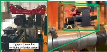
Fig. 9 Composite prepreg tape winding experiment.
The wound product was cured and sampled at the marked position shown in Fig. 10. The metallographic verification method specified in GB/T3365-200829provides the highest porosity detection accuracy. The percentage of the total pore area was measured with an optical microscope. Since the prepreg tape used in the experiment was an orthorhombic braid,specimens with 20 mm length,10 mm width and 10 mm height were obtained along the section perpendicular to the fiber axis.The sample was embedded with an embedding material, and the embedding material was wetted by grinding abrasive paper under flowing water. The polished specimen was placed under a microscope, and the pore number and size were calculated.The process used to measure the porosity of the composite tape winding products was shown in Fig. 11.

Porosity can be calculated using the following equation:where X is the porosity, Svis the total void area, and Stis the cross-sectional area of the specimen.
The measured porosity of the winding products is shown in Table 4.The LQSMC control strategy yields winding products with decreased porosity. The decreased porosity reflects the improved accuracy of the pressure control system.
6. Conclusion
(1) An analysis of the guiding mechanism and a mathematical model for a pneumatic pressure control system are presented in this paper. A robust control algorithm based on linear quadratic optimal control and sliding mode control is proposed for improving the precision of the pneumatic pressure control system. The method is based on a system state space expression and linear quadratic optimal control. The equation of motion for a sliding surface is defined and the system state space model is improved by introducing the control input and state estimation based on a Kalman filter. The proposed control algorithm provides good performance and can effectively suppress SMC chattering.
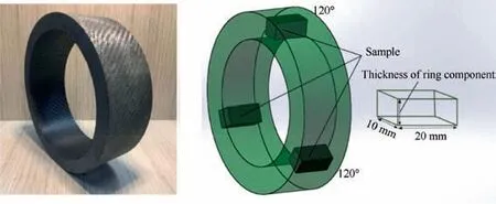
Fig. 10 Photograph and sketch of the samples for testing void content.
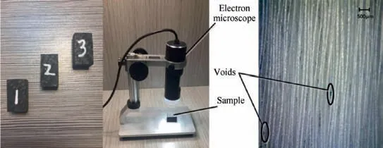
Fig. 11 Process for measuring porosity of composite tape winding products.

Table 4 Comparison of simulation control errors.
(2) The experimental and simulation results show that the LQSMC control scheme provides stronger interference suppression, smaller steady-state error, and robustness compared to LQC. This algorithm can effectively improve the stability and control precision of the pressure control system for composite fiber tape winding molding.The LQSMC algorithm is used to significantly reduce the porosity of composite wound products compared to those produced with the LQC algorithm.
Acknowledgement
This study was supported by the National Natural Science Foundation of China (No.51505356).
 CHINESE JOURNAL OF AERONAUTICS2020年2期
- CHINESE JOURNAL OF AERONAUTICS的其它文章
- Delaying stall of morphing wing by periodic trailing-edge deflection
- Optimization and verification of free flight separation similarity law in high-speed wind tunnel
- Non-intrusive reduced-order model for predicting transonic flow with varying geometries
- Consideration on aircraft tire spray when running on wet runways
- Aeroelastic simulation of the first 1.5-stage aeroengine fan at rotating stall
- Experimental study on NOx emission correlation of fuel staged combustion in a LPP combustor at high pressure based on NO-chemiluminescence
