Delaying stall of morphing wing by periodic trailing-edge deflection
Zi KAN, Daochun LI, Jinwu XIANG, Chunxiao CHENG
School of Aeronautic Science and Engineering, Beihang University, Beijing 100083, China
KEYWORDS Aerodynamics;Computational fluid dynamics;Flexible structures;Morphing wings;Stall angle
Abstract Morphing wings can improve aircraft performance during different flight phases.Recently research has focused on steady aerodynamic characteristics of the morphing wing with a flexible trailing-edge,and the unsteady aerodynamic and stall characteristics in the deflection process of the morphing wing are worthy further investigation. The effects of the angle of attack and deflection rate on aerodynamic characteristics were examined,and based on the aerodynamic characteristics of the morphing wing, a method was developed to delay stall by using the flexible periodic trailing-edge deflection. The numerical results show that the lift coefficients in the deflection process are smaller than those in the static situation at small angles of attack, and that the higher the deflection rate is, the smaller the lift coefficients will be. On the contrary, at large angles of attack, the lift coefficients are higher than those in the static case, and they become larger with the increase of the deflection rate. Further, the periodic deflection of the flexible trailing-edge with a small deflection amplitude and high deflection rate can increase lift coefficients at the critical stall angle.
1. Introduction
Morphing wing aircraft can adapt its airfoil shapes to suit the mission conditions with high operating efficiency and better aerodynamic performance. The recent government-sponsored activities, historical perspectives and future challenges of morphing aircraft systems,1and the classification, performance benefits, and enabling technologies of the morphing wing2have been discussed.Recently, Li et al.3provided an overview about the most prominent examples of morphing wings, as well as the methods and tools commonly deployed for the design and analysis of these morphing wing concepts.
The flexible trailing-edge has become the most commonlyused method for the morphing wings design due to its significant benefits and convenient implementation.4-7A wind tunnel test was carried out to prove that the morphing wing with flexible trailing-edge had better aerodynamic characteristics than a traditional airfoil.8Li et al.9studied the aeroelastic response of a morphing flap showing that the morphing of airfoil can reduce critical flutter speed. A flexible trailing-edge with deformable ribs10and a morphing wing with a double corrugated variable camber11were designed to improve aerodynamic performance. A flexible variable camber trailing-edge flap was designed by Lu et al.12to improve flight efficiency during takeoff, cruise and landing states. Moreover,supported by governments, the American company FlexSys designed a mission adaptive compliant wing of high altitude endurance aircraft with a smooth and variable trailing-edge,and the test results showed that the lift-to-drag ratio could be increased by 3.3% under cruise conditions.13,14Boeing and NASA jointly designed a Variable Camber Continuous Trailing-edge Flap system which was found to potentially reduce nearly 10% drag in the cruise condition.15European Union supported the Smart Intelligent Aircraft Structures(SARISTU) project to accomplish the design of the morphing wing system and manufacture flexible morphing structures.16Morphing wings are used not only in fixed wing aircraft, but also in other devices and vehicles, such as wind turbine17,18and rotor craft.19-22
Aerodynamic analysis plays an important role in the process of translating morphing concepts into designs. Due to the high computational efficiency, the extension of Weissinger’s method23and the vortex lattice method24are often used to obtain steady aerodynamics of the morphing wing.Considering the flexibility of morphing wings, the unsteady vortex lattice method,25,26the doublet lattice method27,28and the CFD method are adopted to estimate the unsteady aerodynamics. By solving the Reynolds-Averaged Navier-Stokes(RANS)equations,the flow transition over the morphing wing surface was predicted,and the numerical results were found in good agreement with the wind tunnel experimental results for the pressure distribution.29.The wind tunnel experimental data and numerical simulation results were compared to prove that the CFD method could be successfully used to perform optimization of the morphing wing.30The CFD method exhibits an adequate application in the cases with large angles of attack and strong viscous flow.
Some studies have researched the aerodynamic and stall characteristics of morphing wings with CFD method. Lyu and Martins31adopted the RANS equations to study adaptive morphing trailing-edge wings,observing 1%drag reduction in on-design conditions, and 5% drag reduction near off-design conditions.Abdessemed et al.32used the CFD method to analyze a NACA0012 airfoil with a morphing trailing-edge; the results revealed that the lift-drag ratio increased by 6.5%and that the local flow field was influenced by the morphing motion. The stall and aerodynamic performance of a NACA0012 airfoil fitted with flexible trailing-edge was investigated by RANS numerical simulations,showing that the morphing surface could delay the onset of flow separation to achieve optimal aerodynamic performance.33,34In addition,Wolff et al.17,35solved the RANS equations to investigate the aerodynamic and stall characteristics of a deformable trailing-edge of wind turbine blade airfoil. The results showed that while deflecting the trailing-edge at angles of attack near stall, the transient lift is higher than the steady lift. Ahaus investigated the dynamic stall behavior of a pitching airfoil with a morphing trailing-edge of helicopters.20-22
In this study, a method for delaying stall by periodic trailing-edge deflection is proposed based on the unsteady aerodynamics of a morphing wing in the deflection process using the CFD method with dynamic mesh.
2. Model and method
A flexible trailing-edge can achieve a chord-wise and span-wise differential camber variation with the same structural system,providing a smooth contour with no additional gap. In this research, the NACA0012 airfoil with a flexible trailing-edge was modeled for the numerical simulation of aerodynamics.To study the aerodynamic characteristics of the morphing wing, the CFD method with dynamic mesh and User-Defined Functions (UDFs) were adopted.
2.1. Model
A model based on the NACA0012 airfoil with a flexible trailing-edge was designed to numerically simulate the aerodynamics of morphing wings. A morphing wing and a conventional wing with a flap are shown in Fig. 1. The morphing section of the morphing wing is in the 60%-100% chord of the airfoil, and the fixed section is in the 0-60% chord of the airfoil.The angle between the chord line and the line connecting the deflection axis to the trailing-edge is the morphing trailing-edge at the deflection angle β which varies in a range of ±20°, with the downward direction as the positive direction. V∞represents the free-stream velocity, and the angle between the chord line and the direction of V∞is the angle of attack α.
2.2. Modeling method and morphing method
Based on Refs. 36,37, this study adopts the parabolic form of morphing. Given its constant thickness, the morphing wing with a flexible trailing-edge can be modeled according to the distribution of the airfoil thickness as long as the morphing form of the mean camber line is known.
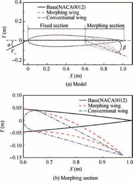
Fig. 1 Comparison between morphing wing and conventional wing.
2.2.1. Modeling method
As shown in Fig.2,the initial deflection point is set as the origin of coordinates(0,0),and coordinate value of the morphing trailing-edge endpoint is (l, Δz). According to the geometric relationship in this figure, the deflection angle and coordinate value of the trailing-edge endpoint can be expressed as tanβ=Δz/l.Then the trajectory equation of the mean camber line is


According to Eqs. (1) and (2), the relationship between deflection angle and coordinate value of the morphing trailing-edge endpoint is obtained. If the deflection angle is determined, (l, Δz) can be determined, and then the equation of the mean camber line can be obtained. According to the thickness distribution of the NACA0012 airfoil, the morphing airfoil shape is obtained on the basis of the mean camber line trajectory. The equations of the upper and lower surfaces of the morphing wing can also be obtained. Then the morphing wing with a flexible trailing-edge is modeled.
2.2.2. Morphing method
In this research, the dynamic deflection of a flexible trailingedge needs to be simulated to study the unsteady aerodynamic characteristics of the morphing wing. The user-defined functions were adopted to achieve the morphing of the flexible trailing-edge by controlling the position of grid nodes. For example, the deflection angle varies in the form β(t)=β0×sin(2πft) with f representing the deflection rate (cycles per second)and β0the maximum deflection angle of the trailing-edge.In the deflection process, the region of 0-60% airfoil chord is unchanged.The equation of the mean camber line of the morphing section is
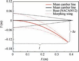
Fig. 2 Trajectory of mean camber line.

and the position of grid nodes of the morphing wing(x(t),y(t))can be obtained at each moment.Finally,the trailing-edge can continuously deflect with the updating position of grid nodes.It should be noted that during the continuous deflection of the trailing-edge, the α remains unchanged.
2.3. Numerical method and validation
In the numerical calculation, the unsteady incompressible RANS equations with the Spalart-Allmaras turbulence model are discretized with the finite volume method. A second-order upwind scheme,a second-order central difference scheme,and the SIMPLE algorithm are used for the convection terms, diffusion terms, and pressure-velocity coupling, respectively. The computational domain sketch and unstructured mesh layout are shown in Fig. 3. The radius of the computational domain is 30 times the chord length c of the airfoil,the boundary of the computational domain is set as a pressure-far-field, and the airfoil is set as a no-slip static wall. As shown in Fig. 3(b),the grid is refined near the airfoil for more accurate results.To validate the accuracy of the numerical simulation, this study compared the lift and moment coefficients of the airfoil NACA0012, using the experimental data and results of the extended-ONERA method.38,39Although the model does not have a flexible trailing-edge, this airfoil experienced the harmonic pitching motion about the quarter-chord. The form of the AoA is

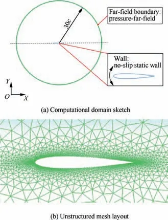
Fig. 3 Computational domain and unstructured mesh layout.
with the Mach number, Reynolds number, and deflection rate f being 0.302,3.78×106and 8.459 Hz,respectively. The comparison between the lift and moment coefficients of the airfoil verified the accuracy of the CFD method with dynamic mesh.
Fig.4 shows that the lift coefficients CLobtained from both the CFD method and extended-ONERA method are slightly different from the experimental data, but trend along similar lines, especially during the increase of the α. A comparison of the moment coefficients Cmof the CFD, extended-ONERA method and experimental data, shows some differences. However, the moment coefficients of the CFD results are closer to those of the experimental data, compared with those of the extended-ONERA method. Therefore, the CFD method is sufficiently accurate in simulating the unsteady aerodynamics.
3. Results and discussion
In this section,the transient aerodynamic characteristics of the morphing wing with a flexible trailing-edge in the deflection process are provided, and then a method for delaying stall of the morphing wing is introduced.
3.1. Unsteady aerodynamic characteristics of morphing wing in deflection
The aerodynamic characteristics of the morphing wing in the deflection process were studied. The trailing-edge of the wing begins to deflect downward at the fourth second until the angle of the morphing trailing-edge increases to the maximum deflection angle 20°,and then remains constant.Meanwhile,the α is fixed in the deflection process. The Mach number is 0.1 and Reynolds number is 2.3×10⁶. The deflection angle varies in the form β(t)=β0×sin(2πft).
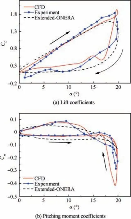
Fig. 4 Comparison among CFD results, experimental data and extended-ONERA method.
3.1.1. Effects of α and deflection rate on unsteady aerodynamic characteristics
The effects of the α and deflection rate on the aerodynamics of the morphing wing are discussed as below.The lift coefficients of the static and dynamic cases are shown in Fig.5.The static case means that the trailing-edge deflection angle is always β0,and the dynamic one means that the initial deflection angle is 0°,and finally remains being β0after the downward deflection.
In Fig.5,for both β0=20°and 15°,the transient lift coefficients are smaller than those of the static case at small α.Higher deflection rate leads to smaller transient lift coefficients. On the contrary, the transient coefficients are higher than those of the static case at large α;transient lift coefficients are larger with the increase of deflection rate.Furthermore,the transient lift coefficients decrease slowly in the stall stage,whereas lift coefficients of the static case drop rapidly. Therefore, the dynamic cases have wider range of effective α.

Fig. 5 Static and transient lift coefficients at different deflection rates.
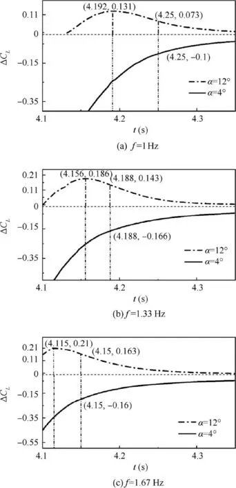
Fig. 6 Differences between transient and static lift coefficients versus time for α=4° and 12° at different deflection rates.
To illustrate the effects of the α and deflection rate in detail,the transient lift coefficients are extracted in the deflection process. Fig. 6 shows the curves of the lift coefficients differences(ΔCL=CLtransient-CLstatic) versus time for α=4° and 12°at three different deflection rates. In Fig. 6(a), the trailingedge deflection rate is 1 Hz, the deflection angle varies in the form β(t)=20°×sin(2πft), and the static lift coefficient is 2.15 at α=4°, and 2.09 at α=12°. As the trailing-edge reaches the maximum angle 20° at t=4.25 s, ΔCLis 0.073 at α=12°,and-0.1 at α=4°.In addition,there is a peak difference 0.131 at α=12° and t=4.192 s. In Fig. 6(b), the trailing-edge deflection rate is 1.33 Hz. The deflection angle varies in the form β(t)=20°×sin(2×1.33πt). As β is 20° at t=4.188 s, the transient difference ΔCLis 0.143 at α=12°,and ΔCLis -0.166 at α=4°. The peak difference is 0.186 at α=12°.In Fig.6(c),the deflection rate is 1.67 Hz.The deflection angle varies in the form β(t)=20°×sin(2×1.67πt).As β reaches 20° at t=4.15 s, the transient difference ΔCLis 0.163 at α=12°,and ΔCLis-0.16 at α=4°.The peak difference is 0.21 at α=12°. Therefore, the transient lift coefficient first increases up to the peak and then decreases slightly to a stable value during the process of the downward trailing-edge deflection, and the difference of the lift coefficient is always larger than 0 at α=12°,and smaller than 0 at α=4°.Furthermore,compared with the static lift coefficients with α=12°, the transient lift coefficient at β0=20° increases by 3.5%, 6.8%and 7.8% when the deflection rates are 1 Hz, 1.33 Hz and 1.67 Hz, respectively. Obviously the higher the deflection rate is, the larger the transient lift coefficients will be. On the contrary, for α=4°, the transient lift coefficient at β0=20°decreases by 4.6%, 7.7% and 9.3% when the deflection rates are 1 Hz,1.33 Hz and 1.67 Hz,respectively.Therefore,at large α, especially at the critical stall angle, the downward flexible trailing-edge deflection improves unsteady aerodynamic characteristics of morphing wings.
3.1.2. Flow field of morphing wing in deflection process
To explain the results in Section 3.1.1, a more detailed study about flow separation and pressure changes was conducted.The α of the static and dynamic cases are both 12°, the maximum deflection angle is 20°,and the deflection rate is 1.33 Hz.As shown in Fig. 7, compared with the dynamic cases, the static case shows a larger vortex attached to the upper surface of the trailing-edge, which indicates a larger flow separation.Thus,the lift coefficients of the static case are lower than those of the dynamic one. Fig. 7(b) and (c) display the streamlines and pressure contours when the deflection angles increase to 19.3° and 20°, respectively. When the separation near the trailing-edge occurs and begins to expand forward, the trailing-edge has already reached another position due to the continuous morphing. Thus, the evolution of the flow field always lags behind the trailing-edge morphing. In addition,the separation in Fig. 7(b) is smaller than that in Fig. 7 (c),which can explain the phenomenon in Fig.6 that the transient lift coefficient increases up to the peak and then decreases to a stable value.These results show that,during the deflection,the morphing wing has better stall and aerodynamic characteristics at the critical stall angle.
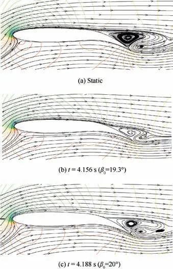
Fig. 7 Flow field and pressure contours of static and dynamic cases at f=1.33 Hz, and α=12°.
3.2. Delaying stall by periodic trailing-edge deflection
The analysis so far has shown that the morphing wing with a flexible trailing-edge has a larger lift coefficient than that of the static case at large α in the deflection process. Thus, we conducted further research to apply this property.This subsection introduces a method for improving stall characteristics with periodic flexible trailing-edge deflection. In the trailing-edge deflection process, the α remains constant.
In this part, this deflection is in the form β(t)=20°+β1-×sin(2πft); the static case means that f=0, and the trailingedge deflection angle is fixed as 15°. The dynamic case means that the flexible trailing-edge deflects periodically with 15° as an equilibrium position. The mean lift coefficients of those cases are shown in Fig. 8. It can be seen that the critical stall angles of the static case are about 13°, and in the dynamic cases, the lift coefficient has still no obvious change when the α reaches to 16°.The mean dynamic lift coefficient of the periodic trailing-edge deflection is larger than that of the static case in the stall stage, and the stall angle increases. Then, a more detailed study was conducted, as shown in Fig. 8 (b). The lift coefficients at α=14°and 16°correspond to the left and right Y-axes, respectively. The result shows that the smaller the deflection amplitude is and the higher the deflection rate is,the larger the dynamic mean lift coefficient will be. Thus, the trailing-edge periodic deflection with a small deflection amplitude and high deflection rate can improve the performance of morphing wings in the critical stall stage.
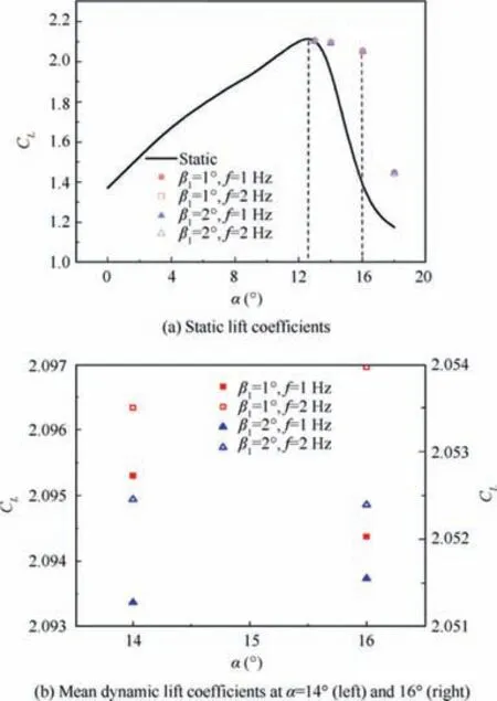
Fig. 8 Static and mean dynamic lift coefficients.
The case of α=16° will be used as an example to analyze the effect of the periodic trailing-edge deflection on lift coefficients.As shown in Fig.9(a),the static lift coefficient begins to decrease when the deflection angle is 10°, while the lift coefficient of the periodic trailing-edge morphing is still increasing.The dynamic lift coefficients changing with the deflection angle present a hysteresis loop,which moves in a clockwise direction and can be seen in Fig. 9(b). Furthermore, the higher the deflection rate is, the more sharply the hysteresis loop slopes;the smaller the deflection amplitude is, the narrower the hysteresis loop is.
This phenomenon can be briefly explained in terms of flow separation.The flow of the static case begins to separate at the deflection angle of 10°, so the lift coefficients are smaller than those of the dynamic cases. For the dynamic cases, during the downward process of the periodic deflection, the higher the deflection rate is,the more slowly the separation expands,leading to a large lift coefficient at the maximum deflection angle.However,during the upward process of the periodic deflection,the reattachment is more difficult with high deflection rate,resulting in a small lift coefficient at the minimum deflection angle. So a sharp slope of the hysteresis loop is generated. In addition,the small deflection amplitude causes a more insignificant difference of the lift coefficients during periodic deflection of the trailing-edge, and a narrower hysteresis loop.
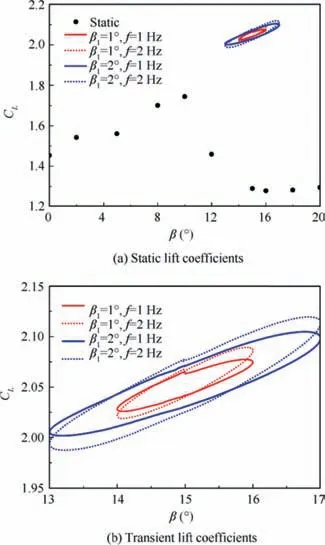
Fig. 9 Static and periodic lift coefficients of trailing-edge deflection at α=16°.
4. Conclusions
The aerodynamic characteristics of the morphing wing with a flexible trailing-edge are investigated numerically in this study.The unsteady aerodynamics in trailing-edge deflection process with different α and deflection rates are investigated.A method is proposed to delay the stall of the morphing wing by periodic trailing-edge deflection.
(1) During the downward deflection of the flexible trailingedge,the transient lift coefficients are smaller than those of the static case at small α. Higher deflection rate leads to smaller transient lift coefficients.However,at large α,especially in the critical stall stage,the transient lift coefficients are larger than those of the static case, and higher deflection rate results in larger transient lift coefficients.
(2) By periodic deflection of the trailing-edge, the airfoil stall can be delayed. The results show that the periodic deflection of the trailing-edge can increase the lift coefficients. Furthermore, a higher lift coefficient will be obtained with a small deflection amplitude and high deflection rate. The lift coefficients present a hysteresis loop, moving in a clockwise direction.
Acknowledgments
The authors are grateful to the anonymous reviewers for their critical and constructive review of the manuscript. This study was supported by the National Natural Science Foundation of China (Nos. 11402014 and 11572023).
 CHINESE JOURNAL OF AERONAUTICS2020年2期
- CHINESE JOURNAL OF AERONAUTICS的其它文章
- Optimization and verification of free flight separation similarity law in high-speed wind tunnel
- Non-intrusive reduced-order model for predicting transonic flow with varying geometries
- Consideration on aircraft tire spray when running on wet runways
- Aeroelastic simulation of the first 1.5-stage aeroengine fan at rotating stall
- Experimental study on NOx emission correlation of fuel staged combustion in a LPP combustor at high pressure based on NO-chemiluminescence
- Research on nonlinear model predictive control for turboshaft engines based on double engines torques matching
