Aeroelastic simulation of the first 1.5-stage aeroengine fan at rotating stall
Feng LIANG, Zhifeng XIE,*, Aiguo XIA,b, Ming ZHOU
a School of Aerospace Engineering, Tsinghua University, Beijing 100084, China
b Beijing Aeronautical Technology Research Center, Beijing 100076, China
KEYWORDS Aeroelasticity;Computational Fluid Dynamics;Midspan shrouds;Rotating stall;Turbomachine blades
Abstract A massive parallel aeroelastic simulation platform has been built to investigate the first 1.5-stage fan of an aeroengine at rotating stall. The Computational Fluid Dynamics (CFD) solver and Computational Structural Dynamics(CSD)solver are coupled directly by non-matching mesh interfaces. The unsteady rotor/stator interaction is solved by the Sliding Mesh Interface method.The original rotor blades are shrouded by the midspan shrouds.An unshrouded fan is also created to investigate the effects of the midspan shrouds. Both the shrouded fan and unshrouded fan have stable aeroelasticity at the designed state. At rotating stall, the stalled region rotates at 30% of the rotor speed on the absolute reference frame.The energy spectrum of the rotating stalled flow is measured quantitatively.It shows that the first two order excitations are much stronger than the higher order excitations.In the flow of rotating stall,the fifth backward travelling wave mode of shrouded fan is resonated by the fifth excitation of the rotational stalled flow because the rotational speed of the stalled region coincides with the modal rotational speed,while for the unshrouded fan,the first bending mode is resonated by the second excitation of the rotational stalled flow, forming two waves in the circumference of the annulus blades. At rotating stall, the vibration of the shrouded blades is still under control but the vibration of the unshrouded blades is diverged and out of control. A novel tool, i.e., resonance map, is proposed to predict the resonance.It provides a perspective to explain the effects of midspan shrouds at a theoretical level, and it would also be helpful in the structural design of blades.
1. Introduction
The high-cycle fatigue failures of compressor blades caused by forced vibration and flutter are always a significant issue for aeroengine. As the rotor speed of the aeroengine is increasing for a high thrust-to-weight ratio, the aerodynamic loads are improved significantly, but the blades of the compressor and the fan trend to use slender, unshrouded configurations with light and flexible composite material. Thus, the risk of excessive vibrations, such as flutter and forced vibration, is increased. The stability of the fluid/structure system is vitally important to the reliability of the aeroengine, and it becomes a key factor that limits the operating range of the engine.Accordingly, the aeroelastic analysis is conducted to solve the problem of Fluid/Structure Interactions (FSI). The FSI vibration of blades can be divided to several groups,including forced response caused by rotor/stator interaction, interactive response from structure-induced unsteady flow separation,and self-excited vibration(i.e.,flutter)caused by the negative aerodamping. All of these phenomena may appear on some offdesigned conditions of the compressor and the fan. For modern designs of aeroengine, the aeroelasticity must be carefully examined, and the flutter and resonance boundaries should be highlighted on the operation map.
Aeroelastic simulation based on high accuracy Computational Fluid Dynamics (CFD) has been used extensively due to the improvement of numerical computation technology.Some programs, such as FUN3D and CL3D released by NASA,are very powerful for the numerical analysis of aerodynamics and aeroelastics. Aeroelastic simulations consist of three parts, i.e., aerodynamics, structural dynamics, and the fluid/structure interface. There are several models that can be used to simulate the unsteady compressible flow of fluids,e.g., the inviscid model (or Euler model), viscous laminar model, Reynolds-Averaged Navier-Stokes (RANS) model,Large Eddy Simulation (LES) model, and the Direct Numerical Simulation (DNS) model. The newly-developed Reduced-Order Model(ROM)improves the efficiency of the aeroelastic computation by using a few CFD calculations and some structural modes.1Silva et al. evaluated the flutter prediction performances of various CFD models, including linear Computational Aeroelasticity Program-Transonic Small Disturbance (CAP-TSD), Euler, RANS, and ROM. The results demonstrated that all of the methods that have been developed have good agreement with the experimental results in subsonic inflow, but, in supersonic inflow, the deviations of the predicted flutter boundaries are significant for the major methods.2Computational Structural Dynamics (CSD) can be solved based on unreduced Degrees-Of-Freedoms (DOFs) of the Finite Element model or reduced structural modes. The former must conduct the data exchange and interpolation between the non-matching meshes of fluid/structure interfaces,3but it is a general method for all the linear/nonlinear and elastic/inelastic structures, and the stress of structure can be obtained directly. Contrarily, for the latter method,although the data exchange can be simplified and the structural dynamics’solver consumes less time,it is cannot simulate nonlinear and large deformed structures, and the local stress fields of structures are difficult to predict precisely.4In this paper,we used the former method,i.e.,unreduced DOFs with Fluid/Structure interfaces for more general applications.
The aeroelasticity of turbomachinery has been studied for decades, and some experiments have been conducted. The aeroelasticity of a series of axial-flow turbomachines was measured by the Advisory Group for Aerospace Research and Development (AGARD), and the results were presented in the literature.5A full engine test was conducted with a special facility in which the conditions of the inlet air could be adjusted. The transient stress of the blades was measured,and the flutter of the compressor blade was detected. One 1.5-stage transonic compressor test rig was designed to validate the aerodynamic performance,and self-excited vibrations of blades were found near the aerodynamic stability boundary of the compressor.6Aeroelastic simulations of turbomachinery also have been conducted by many researchers. In the early years,the aeroelastic analysis usually was conducted in the frequency domain, where the boundaries of aeroelastic stability were determined by the energy of unsteady aerodynamic forces imposed on separate structural modes, and this method is called Energy Method.7The Energy Method is very efficient for weakly-coupled problems with predetermined eigenmodes and natural frequencies, but the prediction of stronglycoupled fluid/structure interactions or complex nonlinear flow may be inaccurate. In recent years, the trend among researchers has been to use the governing equations of structural and fluid motion and integrating in time domain, and this is the approach that was used in this paper.
In the view of their computational complexity, simulated objects can be divided into single blade, full annulus blades,and full annulus stages. The simulations of a single blade usually are focused on the mechanism of blade flutter, such as proposing non-dimensional similarity parameters,8comparing the prediction ability of different CFD models,9developing different time marching methods,10optimizing the shape of the blade to improve the flutter margin,11investigating the effects of tip clearance on aerodynamic performance,12designing the tip clearance to avoid flutter,13and detecting the flutter in reversed flow conditions14and stall conditions.15Simulations of full annulus rotor blades are conducted mainly to investigate some non-axisymmetric effects,including the interaction among multiple blades,16mistuning the frequencies of the blades with aerodynamic asymmetry,17and the process of approaching the stall line.18The analysis of the full annulus stages is closer to the actual physical model of turbomachinery,but the computational costs are very expensive. Many stagescale phenomena can be investigated, such as the rotor/stator interaction,19the effects of intake on the fan flutter,20tip clearance flow among nonsynchronous blades,21and the application of the Generalized Grid Interface method.22
There is a type of flutter, i.e., stall flutter, in which the reversed flow and separation lead to a highly nonlinear performance of the fluid/structure interaction. Compressor stalls can be grouped into two categories, i.e., compressor surge(axisymmetric stall) and rotating stall. In this paper, we concentrated on rotating stall, which usually is the momentary intermediate state between steady state and the complete stall state, and it will end in one of the two states after several to dozens of revolutions. In the rotating stall state, the reverse flow region will appear at the tips of a few contiguous blades, and stalled region will rotate at a speed that is less than the rotor speed. There are two types of stall inception, modal inception and spike inception, related to the long lengthscale and short lengthscale disturbance respectively. Vo et al. numerically investigated the phenomenon of the rotating stall, and proposed some criteria to define the spike type of rotating stall inception.23Wang et al. utilized the energy method to investigate stall flutter, and they found that the shock wave and separation on the suction surface were important factors that induced flutter.24Hu et al. numerically investigated the intricate flow structures around the blade tip region of the multi-passage domain.The results indicated that the rotating instability phenomenon occurred at the tip of the blade and propagated along the circumference with the strong interaction between the tip leakage vortex and the shock wave.25The aeroelastic performance of the compressor at rotating stall was investigated by Zhang et al. and the results showed that the stalled region rotated at 35% of the rotor speed at the absolute reference frame, and the forced vibration caused by passing through the stalled region had a significant magnitude.26Hou et al. simulated the separation of the flow and the vibration of the blade in the rotating stall at 80% of the nominal rotor speed, and they found that the vibration of the blades at 80% of the nominal speed was more violent than the vibration at 100% of the nominal speed.27
Some fans and compressors use the midspan shrouds to reinforce the torsional stiffness, especially in many military turbofan engines with low bypass ratios. In this paper, fans with midspan shrouds are called shrouded fans, and the fans that do not have midspan shrouds are called unshrouded fans. Unshrouded fans have been installed extensively in high-bypass-ratio civil aeroengines with wide-chord blades,and now they are being used in some newly designed military aeroengines and gas turbines. For example, the first stage compressor of the famous marine gas turbine,LM2500, was designed with midspan shrouds in 1970s,but, when it was upgraded to LM2500+ in 1998, the design of the first stage compressor used wide-chord, unshrouded blades.28Therefore, the effects of the midspan shrouds on the structural dynamic behavior of blades should be investigated thoroughly, which will help the designers become acquainted with any problems that may occur after the midspan shrouds are removed. The midspan shrouds of all of the blades are not connected directly. Nicholas pointed out that the midspan shrouds can dissipate the vibration of the blades by the slippage and friction that occur on the inter-blade contact surfaces.29Shan et al. researched the damping performance of the midspan shrouds, and they concluded that the midspan shrouds greatly control the response of the first bending mode.30Hsu et al. used the energy method to predict the flutter and the forced response of a shrouded fan. They developed the approach of complex mode analysis, and this approach can be used successfully to analyze the self-excited flutter and forced response.31A fullscale experiment of a gas turbine engine was conducted by Vedeneev et al. to validate the prediction ability of simulation. The results showed that the midspan shrouds significantly improved the aeroelastic stability of the blades.32
The effects of rotating stall on the aeroelastic behavior have been studied by some researchers, but few of them are based on multiple-stage model and directly coupled fluid/structure simulation. The uncoupled or indirectly coupled results may show unpersuasive conclusion. Besides,how the midspan shrouds affects the aeroelastic behavior at designed and off-designed states has not been quantitatively checked. In this paper, the aeroelastic performances of the first 1.5-stage aeroengine fan were simulated by selfcoded program. A rotating stall was conducted to analyze the relation between the resonated structural modes and the energy spectrum of stalled flow. An unshrouded fan was created by removing the midspan shrouds from the original shrouded fan for comparison. The mechanism of the midspan shrouds affecting the resonance in the stalled flow was summarized on a theoretical level.
2. Method
We have coded an aeroelastic simulation program using C++that we named the CFSD-Platform (v1.0), which has the ability to conduct massive parallel computations and can run on both a personal computer and a multi-nodes super computer.This program consisted of five basic modules,i.e.,CFD,CSD,moving mesh, sliding mesh, and the fluid-structure interface.The fluid based on the Finite Volume Method(FVM)of Arbitrary Lagrangian-Eulerian (ALE) and the structure based on the Finite Element Method (FEM) were coupled directly with non-matching mesh interfaces and integrated in the time domain. The detailed methods are presented in the following sections.
2.1. CFD equations
The integral form of compressible unsteady RANS equation is:

where W is the conservative variable vector, Fnis the normal flux, H is the source term, V is the controlled volume, S is the surface of controlled volume. Shear Stress Transport(SST) turbulence model33is used, so the conservative variable is defined as:

where the ρ is the density of fluid,U is the flow speed vector,E is the total energy, k is the turbulent kinetic energy, ω is the turbulent frequency. The equation is solved based on Finite Volume method with the Arbitrary-Lagrange-Euler (ALE)view. The cell-averaged Partial Differential Equation (PDE)for each cell (or control volume) is

where Q is the total amount of conservative variable in each cell, t is the time, m is the number of cell faces, i is the index of cell face. The second order backward difference scheme is the most common method for time discretization, which is shown as:

or in other form:

This discretization is stable for most situation, while in some case, it is not stable for CFD integration. If the density ρ or pressure p steeply decrease from Step (n-1) to Step(n), the unphysical negative pressure or negative density may be generated at Step (n+1). This extreme situation usually happens when the strong shock or separation occurs and the local time integration step is not small enough to capture the rapidly changed filed. In this paper, a novel modification is made to enhance the robustness of the time discretization,which is shown as:

where ξ is order-control parameter, which can be different for each cell. The discretization will be the traditional second order backward difference scheme as ξ equals to one. If ξ is set to 0.5,the discretization degenerates to the commonly used one-order difference scheme.ξ is determined by the local timederivative magnitude of the pressure and density. When the density or pressure steeply changed, the time derivative term is usually dominant,the flux and source term can be neglected,and the equation is simplified as:

The local value of ξ should equal to 1 for second order accuracy when the time derivative is moderate, and approach to 0.5 for the severely changed region. Here, a suggested formulation is proposed to get the value of ξ, which is:

This modification can enhance the numeric stability, especially for aerodynamic simulation of the stalled compressor,where the shock and separation can be strong and complex around the blade tip region. This modified method is named Order-Variable Time Discretization (OVTD) method in this paper.
2.2. CSD equations
The general structural dynamic equation for small deformation is:

where M,C,and G are the global mass,damping and Coriolis matrix respectively. Vector q is the displacement. The stiffness term consists of three matrices:material stiffness Km,spin softening Kcand prestress stiffening Ks. The pin softening is usually insignificant compared with the centrifugal prestress stiffening for the aeroengine rotor. The damping matrix are estimated by a linear combination of mass and stiffness,which is known as Rayleigh damping. The structure is discretized by the Finite Element Method(FEM).The generalized α method,an implicit second-order method with adjustable numerical damping, is implemented to solve the transient response of structural system.
2.3. Moving mesh method
Fluid mesh needs flexible deformation to adopt the moving boundaries. In this paper, a block-element method is developed for multiple-blocks structured mesh of fluid. The fluid mesh is treated as a ‘‘elastic frame”, where each block of the fluid mesh is an element of the frame, so the block number of the fluid mesh is the element number of the frame,as shown in Fig.1.In this way,the problem of moving mesh changes to the statics problem of ‘‘elastic frame”, which can be solved by the Finite Element Method:

where Kmis the frame stiffness matrix,ΔXmis the displacement of the element nodes, Fmis the equivalent force of the mesh frame. The moving boundaries are regarded as the displacement constraints for the mesh frame, and the displacement of the nodes on these boundaries are predetermined. Other outer boundaries of the fluid field can be treated as free, fix or slip boundaries for the mesh frame.
The second-order element is used in the frame for better flexibility, thus each line of the frame has two corner nodes and one middle node. Once the movements of the frame are solved,the displacement of the fluid mesh blocks’ border lines can be interpolated by the three nodes of the frame line, as shown below:

where u represents the displacements of the block’s border line node, namely Δx, Δy and Δz; s is the node’s curvilinear coordinates ranges from 0 to 1.Point 0 and 1 are the corner nodes of the frame segment with s equals 0 and 1, point 1/2 is the middle nodes with s equals 1/2. Before this interpolation, the displacement of point 1/2 should be limited to prevent the large curvature:

Fig. 1 Samples for fluid multiple-blocks mesh and flexible mesh frame.

where ε is recommended to 0.25-0.4, by which the interpolated value u can be limited in the range of u0to u1.
After that, the displacement of blocks’ surface nodes and inner nodes can be interpolated by Infinite Interpolation method successively.It should be noted that the blocks border line and surface nodes must be set to the designated displacement if the lines or surfaces belong to a certain moving boundaries. The moving mesh speed can be calculated by the difference of the new generated mesh and the old mesh of the last step. The backward difference method can be used to obtain the second-order accuracy of the mesh speed.
2.4. Sliding mesh interface
For the simulation of unsteady flow between the rotor and stator domains, the rotor/stator interface is sliding. Data should be exchanged and interpolated through the interface at each time step.Schedules of sliding mesh interaction are:Projection,Overlap and Interpolation.
The Projection process is mapping the 3D sliding mesh interface to 2D mesh. The rotor/stator interface of axial stage is annulus, while in radial stage, it is usually a cylinder. As shown in Fig. 2(a), the annulus interface projects towards the axial direction, while the cylinder interface needs to be splitted along a generatrix and paved to a rectangle.
In the Overlap process,a pair of mapped 2D sliding meshes overlap each other,as shown in Fig.2(b).For each cell face i of the one mesh, the overlapped cell faces {j} of the other mesh can be identified, and the occupied area ratio φijcan be calculated.
The Interpolation is to calculate the cell-center field value of virtual grid outside the sliding mesh. Fig. 2(c) shows the sliding mesh interface SAand SBbetween Mesh 1 and 2. The virtual cell value of SAcan be interpolated by the area weight:

2.5. Fluid-structure interface
On the interface of the fluid and structure, the pressure and shear of fluid boundaries should be transferred to solid boundaries, while the displacement of the solid boundaries should be sent to the fluid boundaries.
Fluid force to structure:calculate the integral points’coordinates of structural surfaces and figure out the located fluid surfaces for each integration point, as shown in Fig. 3. The recommend number of integral points is 7 (Hammer integral points,5th order)for each triangle surfaces and 16(Gauss integral points,7th order)for each quadrilateral surfaces.Stress of integral point equals to that of the corresponding fluid surface.The fluid force fseof a structural surface (numbered s) can be integrated as:


where k is the node number, fkis the nodal force, Nskjis the interpolation function value of node k at the Gauss integral point of the surface s.
Structure displacement to fluid mesh: for each node of fluid mesh surfaces,find the nearest structural surface,and calculate the standardized coordinates of the fluid mesh node in the corresponding structural FSI surface. Then the displacement ΔX of the fluid node can be obtained by:

where Niis the interpolation function of structural surface node i, (ξ,η) is the standardized coordinates of the fluid mesh node in this structure surface, ΔXiis the displacement of the structure surface’s node i.
2.6. Coupled time integration

Fig. 2 Schedules of sliding mesh.

Fig. 3 Overlap of fluid-structure interface.

Fig. 4 Procedure of a complete aeroelastic simulation.
Fig. 4 shows the complete procedure of an aeroelastic simulation. Before the coupled simulation, the centrifugal deformation and pre-stress stiffness were calculated by CSD, and the steady fluid field also was simulated by CFD. Next, the static aeroelastic simulation was conducted, during which the static deformation of the blade and fluid field were solved by dozens of steady coupled iterations.Then,the static aeroelastic results were used as the initial state for the transient simulation. For faster convergence and less computation time, the transient coupled simulation was divided into two phases. The first phase was a short period of time after the start, when some artificial damping was added to dissipate the initiallyactivated natural frequencies as quickly as possible. The second phase was the official transient simulation of the aeroelastic simulation. The prediction-correction method was used for the time integration of the coupled Fluid-Structure system, in which the inner iterations were applied at each time step to converge the fluid force and structural displacement.
2.7. Validation
Two standard cases were simulated to validate the CFSDPlatform. The first is the AGARD wing 445.6 Flutter case,which was used to verify the ability to predict flutter.The second is the NASA Rotor 37 case,which showed the accuracy of the simulation of the turbomachine’s aerodynamic performance.
(1) AGARD wing 445.6 flutter case
This case was tested at the NASA Langley Research Center in 1961.34It has been used extensively to validate aeroelastic simulation programs. The AGARD 445.6 wing has a quarterchord sweep angle of 45°,an aspect ratio of 1.644,a taper ratio of 0.6592, and a wing semi-span of 762.0 mm. Its root chord and tip chord are 558.8 mm and 368.3 mm, respectively. The tested flutter boundaries were at the zero-inflow attack angle with Mach numbers of 0.499, 0.678, 0.901, 0.960, 1.072, and 1.141. Many programs and methods were compared with the experimental results. Most of them coincided well in the subsonic condition, but there were considerable deviations in the supersonic condition.2Fig. 5 shows the experimental and simulated non-dimensional flutter boundaries,where subplot(a)is the flutter boundaries and subplot(b)is the critical frequencies of the flutter.The Vfis the non-dimensional flow speed of inlet air, and ωfis the non-dimensional flutter frequency. SA is the abbreviation of Spalart-Allmaras turbulence model. The simulated results obtained in our research were compared with experimental data35and other researcher’s simulations of the inviscid Euler model36and the RANS model.2It should be noted that the relatively large deviations at the supersonic condition should not be ascribed to the accuracy of the program,but to the fact that the flutter boundary is very sensitive to the damping of the whole fluid-structure system at the supersonic flow. Any minor deviation of geometrical measurement or structural damping will lead to large deflection of flutter boundary. Therefore, the criterion of agreement should be moderately relaxed at supersonic condition, so in this prerequisite, the results of this paper are in good agreement with the results of others.

Fig. 5 Experimental and simulated non-dimensional flutter boundaries.
(2) NASA Rotor 37 case
Aerodynamic performance of NASA Rotor 37 was tested at the NASA Glenn Research Center in 1996.37Rotor 37 is an isolated axial impeller, so the rotor/stator interaction effects are avoided. The detailed geometry and aerodynamic performances were measured for code verification. Rotor 37 has 36 pieces of blades, and its designed rotational speed was 1800 rad/s with 20.19 kg/s of mass flow and 2.106 of total pressure ratio.In this paper,we conduct the simulation of the performances of Rotor 37 at its design speed,and the results were compared with the experimental results. The chocked mass flow was measured experimentally as 20.93 kg/s, and the simulated result from the other’s literature38is 20.56 kg/s. For comparison,we obtained 20.80 kg/s.Fig.6 shows comparisons of the experimental determination of the total pressure ratio and adiabatic efficiency among experiments, other’s simulations,38and our results, where q is the mass flow rate, qmaxis the blockage mass flow rate. The two simulated results coincided well, but both had a little but acceptable lower pressure ratio and efficiency than the experimental results.
3. Mesh and modes
Fig. 7 shows that the first 1.5-stage aeroengine fan consists of three annular cascades, i.e., the first stator, the first rotor (call‘‘the rotor” for short), and the second stator. The number of blades of these three cascades are 23, 37, and 54, respectively.The rotor is made by titanium alloy.The tangential velocity of tip of the rotor blade is about 1.4 Ma, and that of root of the blade is about 0.74 Ma. Thus, the fan is operating in a transonic condition. Only the rotor blades are treated as flexible structures;the stator blades are considered to be solid and static. The blades of the rotor cascade are strengthened by midspan shrouds, which are designed to increase the torsional stiffness of the blades and dissipate vibration energy.The midspan shrouds may impact and rub each other in a real situation, but it is too difficult for simulation. So, in this paper,the midspan shrouds are connected directly as a single part.The simplified model is reasonable,because the simulation discussed in this paper is at the highest rotor speed(i.e.,the highest rotor speed is the designed speed) where the midspan shrouds usually are clamped to each other.39In this paper,we present an unshrouded fan that was created by removing the midspan shrouds from the original shrouded fan to investigate the effects of the midspan shrouds.
The aeroelastic performance of the 1.5-stage fan was simulated by the CFSD-Platform.The blades of the stator were considered to be static, rigid bodies, while the rotor blades were modeled as flexible structures based on the linear-elastic,small-deformation principle. The moving mesh method was used for the fluid domain.The data exchange was implemented on the non-matching fluid/structure interface. Sliding meshes were built and used to connect the rotor with the two stators.
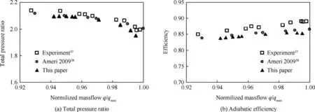
Fig. 6 Experimental and simulated performances of Rotor 37 at designed rotational speed mesh and modes.
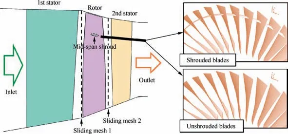
Fig. 7 Meridian view of the first 1.5 stage aeroengine fan.
3.1. Mesh information
The meshes in shrouded fan and unshrouded fan are almost the same except that the space of midspan belongs to fluid domain in the unshrouded fan or to solid domain in the shrouded fan. This paper only shows the meshes of the shrouded fan. Fig. 8 shows the surface of the fluid mesh.The mesh domains colored by red, black and blue represent the first stator domain,the rotor domain and the second stator domain. Each cascade has an independently structured mesh domain, and they are connected by the non-matching Sliding Mesh Interfaces. The cell numbers per passage are 1.2×105,5.4×105and 1.4×10⁵for the three cascades,i.e.,the first stator,the rotor,and the second stator.The total number of cells is approximately 30 million. The clearance of the tip of the rotor blade is filled by 16 layers of mesh. The y+of the first layer of mesh around the solid boundary is about 0.5 to 3,which is enough for the calculation of the boundary layer by the RANS model with a wall function. The rotor domain is solved by moving mesh, while the domains of the two stators use static mesh.
Blades and midspan shrouds are discretized by 20-node,second-order quadratic elements. The total number of elements of the full annulus blades is 2.9×10⁴, and the total number of nodes is 2.1×10⁵. The surfaces of the roots of the blades are set as fixed constraint boundaries,and other surfaces have fluid/structure interfaces.
The aeroelastic simulation of the 1.5-stage fan was run on the commercial supercomputer platform ParaGrid1. Ten 24-core nodes were used, and a complete transient aeroelastic simulation took about a week.
The fluid mesh moves as the structure moves. If the deformation of the structure is too large,the volumes of some of the fluid mesh cells will be negative,which will crash the CFD solver. The mesh deformation ability is determined by the initial quality of the mesh and the moving mesh solver.This ability is vital for the aeroelastic simulation at a rotating stall,where the vibration of the blade can be very violent. A quantitative definition of the mesh deformation ability is proposed in this paper.
The steady fluid force at designed state can be calculated by CFD. Multiply the force by the variable α (which can be negative), and then impose the enlarged force to the structure of the blade. As a result, the structure of the blade and the fluid mesh will be deformed. The variable, α,should be limited to a certain range to avoid negative-volume cells in the fluid mesh.The limitation range is set as [αn, αp], where αnand αpare the negative and positive limitation boundaries,respectively.If α is located out of the limitation range, negative-volume cells will appear in the fluid mesh.The limitation range of α can be used to represent the ability of the fluid mesh to deform. For the case used in this paper, the ability of the fluid mesh to deform was calculated as shown in Table 1.The fluid mesh can sustain the deformation caused by 4-5 times the force of the steady fluid,and the tip of the blade can move more than 5 mm.This mesh deformation ability is enough to simulate the large vibration of the blade at the off-designed state.
3.2. Structural modes
The modes and frequencies are important characteristics for structural dynamics. The modes are solved by the matrices:M,G and K.Due to the asymmetric matrix G,the solved eigenvalues can be complex. For a mode with complex eigenvalue,the local phases of all positions on the structure are different,so the mode behaves as a travelling wave.If the eigenvalue of a mode is real, the mode is performing as a standing wave.
The modes of the full annulus shrouded blades can be grouped as Torsional(T)modes,Bending(B)modes(or nodal circle modes,abbreviated as nT and nB,where n represents the nth order), and circumferential Travelling Wave (TW) modes(nodal diameter modes). Torsional modes usually trend to cause blade flutter, but, in the shrouded rotor, this is suppressed by the midspan shrouds. Fig. 9 presents the first two bending modes and the first six TW modes of the shrouded blades. The eigenvalues of bending modes are real, so it is standing wave and all the blades are in-phase. Because of the complex eigenvalue,a TW mode performs as a circumferentialwave propagating (or rotating) around the annulus. If the direction of the propagation of the TW mode is the same as the direction of the rotation of the rotor, the TW mode is called the Forward TW (FTW) mode; otherwise, it is called the Backward TW (BTW) mode.

Table 1 Limitation range of α,and blade displacements when α locates on limitation boundaries.
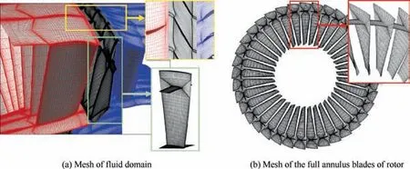
Fig. 8 Surface mesh of fluid and structure domain in shrouded fan.
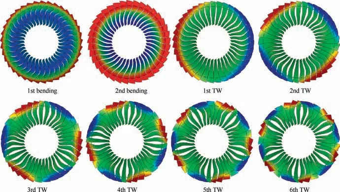
Fig. 9 Modal shapes of the full annulus shrouded rotor blades.
The Campbell maps of the bending modes and TW modes of the shrouded rotor is presented in Fig. 10. The frequencies of the modes are increased as speed of the rotor increases,which is due to the effect of the stiffening of the centrifugal stress. The frequency deviations of the forward and backward TW modes are caused by the Coriolis effect,which seemed not to be significant for this case.All of the modes are not crossed with the rotor speed, so the critical speed of the blades is avoided.
The blades in the unshrouded fan are independent, so the modal analysis only needs to be conducted for one blade.Fig.11 shows the frequencies and shapes of the first six modes of the unshrouded blade. There are two modal types, i.e.,Bending (B) mode and Torsion (T) mode. It should be noted that there are no TW modes for a single unshrouded blade,and all of the Bending and Torsion modes of the unshrouded blade do not bifurcate into Backward or Forward types as the TW modes do.
If the modal phases of the annulus blades rank as an arithmetic series in the circumferential direction, the mode will be shown to be rotating with a certain speed, just as the TW modes do. For annulus blades, a mode has three characteristics, i.e., shape, frequency, and modal rotational speed. The three characteristics of the unshrouded and shrouded annulus blades are listed in Table 2.Because of the independence of the unshrouded blades, the modal phases of all blades also are independent, which indicates that the rotational speed ratio of the unshrouded annulus blades can be any value. The first bending (1B) mode of the shrouded blades is marked as‘‘Infinite,” which is because all the blades in the 1B mode are in-phase, so the rotational speed ratio of the 1B mode is infinite. The TW mode of the shrouded blades has a definitive rotational speed, which is calculated by ΩTWn =±f/n, whereis the rotational speed of the nth order TW mode, f is the frequency,the forward type is positive,and backward type is negative.The BTW modes are very important because many excitation sources,such as stalled flow and inlet distortion,are rotating backward in the view of the rotational reference frame of the rotor, so they have a chance to be resonated.

Fig. 10 Campbell map: frequencies of the full annulus shrouded rotor blades at different rotor speed.
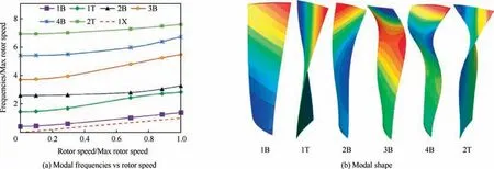
Fig. 11 Modes of unshrouded blade.

Table 2 Some important modes of unshrouded and shrouded annulus blades.
4. Results at non-stalled state
The aerodynamic and aeroelastic simulations are conducted at the non-stalled state for the shrouded fan and unshrouded fan.The non-stalled state is the operational range where the fan is operating steadily without any stall or surge.The results of the unshrouded fan are compared with those of the shrouded fan.
4.1. Effects of midspan shrouds on the aerodynamics
We first investigated the effects of midspan shrouds on the aerodynamic performance of the fan. The midspan shrouds occupy a small amount of the space of the flow passages of the cascades, so the aerodynamic performance will be improved after removing the midspan shrouds. The effects of midspan shrouds on the fluid field at designed state are shown in Fig. 12. A slice plane is placed in the inter-blade passage,where the pressure contour and streamlines are plotted on the rotor rotational reference frame. The shock wave in the passage is conspicuous, and it is split and distorted by the midspan shrouds.The streamlines around the midspan shrouds do not show any separation, so the design of the midspan shrouds successfully has avoided the extra separation loss.
To quantitatively present the influence region of the midspan shrouds, the distribution of the mass flow, total pressure ratio, and efficiency along the radial direction at the outlet of the rotor cascade (Sliding Mesh 2) were calculated, and they are shown in Fig. 13. The y axis is the radial position, which is defined as the relative position between hub (y=0) and the casing shroud (y=1). The non-dimensional mass flow rate, frin Fig. 13(a) is defined as: fr=∫
R=rρundθ/2πρ∞a∞,where ρ is density, unis the normal velocity, ρ∞is the stagnation density of the inlet, and the a∞is the stagnation sound speed of the inlet. It can be found that the deficit of aerodynamic performance in the shrouded rotor is concentrated only around the midspan shrouds,especially on their upper regions.The further region rarely is influenced.
Fig. 14 shows the aerodynamic map of the fan at the designed rotor speed. The mass flow rate, total pressure ratio,and adiabatic efficiency are varied with the change in the average static pressure of the outlet. The pressure ratio is the ratio of the pressure to the inlet total pressure. It was found that,after removing the midspan shrouds,the improvement of aerodynamic performance not significant; the mass flow rate only improved by 0.06%-0.12% (relative value), the pressure ratio only improved by 0.08%-0.22%(relative value),the efficiency increased by 0.09%-0.30% (absolute value), and the surge boundary was extended a little. Therefore, the midspan shrouds were well designed and had little influence on the macroscopic aerodynamic performance.
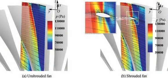
Fig. 12 Pressure contour and stream lines on inter-blade section at designed state.
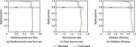
Fig. 13 Distribution of circumferential averaged aerodynamic performance along the radial direction at Sliding Mesh 2.
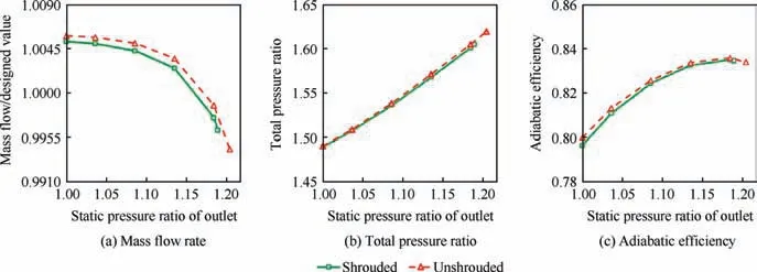
Fig. 14 Aerodynamic maps for unshrouded and shrouded fans at designed rotational speed.
4.2. Aeroelasticity at designed state
The designed state is a special non-stalled state where the fan is designed to operate. The fully coupled fluid/structure simulation of the unshrouded fan first was conducted at the designed state. The vibration of the blades can be extracted and compared with the results of the shrouded fan.
Fig. 15 is the vibration of a shrouded blade and an unshrouded blade, where the displacement and stress of a certain blade are extracted as the representatives. The axial displacements of the tips of both the shrouded and unshrouded blades have very low fluctuation magnitudes,i.e.,smaller than 30 μm near the end of the simulation, thus the dynamic displacement and stress are insignificant for the comparison at the designed state. The average values of the displacements and stresses of the shrouded and unshrouded blades are significantly different. The axial displacements of the tips of the shrouded and unshrouded blades are about 1.0 mm and about 1.8 mm, respectively. Although the axial displacement is increased after the midspan shroud is removed, the stress at the root of the blade decreased, especially at the trailing edge,where the stress was reduced from 430 MPa to 220 MPa.

Fig. 15 Transient results of a certain blade at designed state.
To determine why the stress is reduced so much for the unshrouded design, the stresses were calculated by considering only the centrifugal load and the condition that involved both the centrifugal and fluid loads, as presented in Fig. 16,where S is the equivalent stress. It shows that the large reduction of stress after removing the shrouds from the midspan is due to the absence of the centrifugal load from the midspan shrouds.
The comparison of two figures also indicates that although the stresses of the roots of blades are dominated by static centrifugal load, the stress at the trailing edges of the roots has more component of the fluid load.This suggests that the stress at the trailing edges of the roots is more sensitive to the unsteadiness of the fluid field and that its magnitude may vary to a greater extent at the rotating stall.
Consequentially, from the perspectives of both the structural strength and aerodynamic performance,the above results obtained from the non-surged designed state may indicate that the installation of midspan shrouds only leads to negative effects. Of course, it should be incorrect. Next, the effects of the midspan shrouds will be investigated further at the offdesigned state, and its benefits will be proved.
5. Results at rotating stall
The rotating stall is a stalled state that the reverse flow region appears at the tips of a few contiguous blades, and stalled region rotates at a speed that is less than the rotor speed.The aeroelastic simulation are conducted at rotating stall for the shrouded fan and unshrouded fan.
5.1. Fluid field at rotating stalled
The initial stalled flow was obtained by steady CFD calculation. The procedure is adjusting the outlet average pressure near the stall point until the surge and reversed flow appear around a few adjacent blades. We initialized the rotating stall state with the mass flow rate of 76%of the design value.At the state of the rotating stall in the shrouded fan,the total pressure ratio and the efficiency are 98%and 73%of the design values,respectively. Fig. 17 shows the axial flow velocity u at Sliding Mesh 1 (between the first stator and the rotor), where T is the period of the rotor’s revolution, and the plot view is at the absolute reference frame. The negative axial velocity area,colored blue,represents the reverse flow region(also called the surge or stalled region). It is found that the rotating stall is related to the surge of the tip of the blade,and it has influenced almost half of the annulus. The stalled region rotates in the same direction as the rotor, but its rotational speed is much slower than that of the rotor.
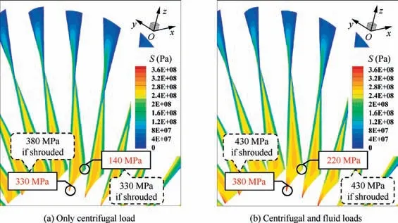
Fig. 16 Equivalent stress of unshrouded blades (red text) and shrouded blades (black text).
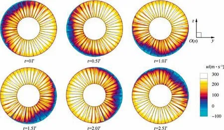
Fig. 17 Time-varied axial velocity contour at Sliding Mesh 1 based on absolute reference frame, where rotor is rotating in counterclockwise direction on this view.
In Fig. 18, the phenomena of the surge of the blades are clearer. The pressure contour and the streamline of the transient fluid field at t=2.5T are sliced by the radial isosurface near the tips and axial section at the middle of the rotor blades.The streamlines are plotted at absolute reference frame for the domains of two stators and at the rotational reference frame for the rotor domain. Subfigure (a) is the threedimensional radial iso-surface, Subfigure (b) shows the radial and spanwise flow, Subfigure (c) contains the twodimensional radial iso-surfaces at different radii R. The RtipRmidand Rrootare the radius of blade’s tip,mid-span and root respectively.It indicates that both the rotor and the stators are surging in the stalled region.The reversed flow crosses over the second stator and swarms into the rotor passage. A small amount of the flow even reaches the first stator and it indicates that surge and separation occur around the tip and midspan of the blades. The tip region is severely surged, and the tip leakage is enlarged, so complex three-dimensional vortices are induced. The surge near the midspan position is much milder,i.e.,a spanwise separation vortex spreads from the roots of the blades to the midspan shrouds.
The rotating stall phenomenon in unshrouded fan is very similar to that in the shrouded fan. To measure the rotational speed of the stalled region quantitatively, we calculated the mass flow focus at Sliding Mesh 1. The mass flow focus will deflect off the center of the axis because the stalled region is not axisymmetric. The focus will rotate with the same rotational speed as the stalled region. Fig. 19 shows the transient angular position of the mass flow focus at different rotational angles of the rotor. Viewed on the absolute reference frame,the ratio of the rotational speed of the stalled region to the rotational speed of the rotor was 0.313 for the unshrouded fan and 0.297 for the shrouded fan.If viewed on the rotational reference frame of rotor, the two values are -0.686 and-0.703,where the‘‘-”means the rotational direction is opposite to that of the rotor.The difference between the two values is very small, which supports the conclusion of the analysis of the aerodynamic performance, i.e., that that the midspan shrouds have little effect on the macroscopic aerodynamic behavior at either designed state or rotating stall state.
5.2. Decomposition of the rotating stalled flow
In order to quantitatively measure the energy spectrum of the stalled flow, the fluid field was decomposed to the frequency domain by Fast Fourier Transform (FFT). The transform of the all three dimensional fields would be too complicated,and it is also unnecessary, so, for our analysis, we only extracted the pressure field of the Sliding Mesh 1 interface.The FFT is based on the rotational reference frame of the rotor.
The major decomposed modes of the stalled flow is shown in Fig. 20, i.e., 1Ωs-5Ωsand 23Ωr, where Ωsis the rotational speed of the stalled region on the rotational reference frame of the rotor, Ωrare the rotational speeds of the rotor. The nΩsor nΩrrepresents the excitation with a frequency of n times Ωsor Ωr. Pris the static pressure ratio to inlet total pressure.As described in the structural modes,the flow modes also have complex eigenvalues.The flow modes behave as the circumferential travelling wave (similar to the BTW modes of the shrouded annulus blades). The real-time pressure of a mode can be written as:

where the p~m is the dynamic pressure at time t and position X,Pmis the amplitude of the local pressure, fmis the modal frequency, and φmis the local phases. The rotational speed of a flow mode can be calculated by Ωm=fm/n,where n is the total wave number in the entire circumference. Therefore, the circumferential wave numbers can be counted by Fig. 20, and the rotational speed of the nΩsmode can be obtained to be Ωsand that of 23Ωris Ωr.The rotational directions of these modes are all opposite to that of the rotor on the rotational reference frame of the rotor.
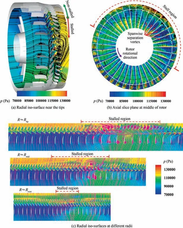
Fig. 18 Pressure contours and stream lines of transient fluid field at t=2.5T.
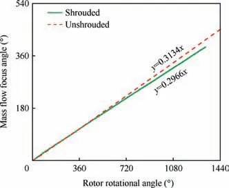
Fig.19 Transient angular position of Mass flow focus at Sliding Mesh 1. The view is based on absolute reference frame.
For the rotor blades, the nΩsmode is the nth order excitation of the stalled flow, and 23Ωris the excitation of the first stator sweeping. A quantitative definition of the intensity of a flow mode at the interface is proposed here, and it is calculated by:

where Φ is the non-dimensional intensity of a flow mode, r is the local radius,and R0is the radius of the hub,Pt0is the total pressure of the inlet,SL is the sliced surface.It should be noted that this definition of intensity is weighted by the radius because the deformation of the rotor blades is more likely to be determined by the bending moment than the axial force.
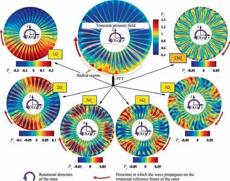
Fig. 20 Major decomposed modes of transient pressure of rotating stalled flow at Sliding Mesh 1. The view is based on the rotational reference frame of the rotor.
Fig. 21(a) shows the energy spectrum of the stalled flow in the unshrouded fan. It is found that there are two clusters of modes, i.e., the 1 to 6 order excitations of the stalled flow,i.e., the 1Ωs-6Ωs, and the other is concentrated around the sweeping excitation of the first stator, which can be written as 23 Ωr±(0-3) Ωs. The latter cluster of modes has the properties of high frequency(high frequency means large damping)and small intensity, which may lead to little responses on the blades, so these modes are not investigated further. Fig. 21(b) compares the energy spectrum of the shrouded and unshrouded fans.The intensities of the 1Ωs-6Ωshad little deviation between the two types of fans. From the 1Ωsto the 3Ωs,the intensity decreased significantly, while for the succeeding excitations the intensity decreased slowly,so the first two order excitations much more powerful than the higher order excitations.
5.3. Aeroelasticity at rotating stalled
The responses of rotor blades were extracted from the results of the coupled fluid/structure simulation at rotating stall.Fig. 22 shows the contours of the axial displacement of the blades, qx, which is plotted at rotational reference frame.The red numbers from 1 to 5 with circular border are used to mark the position of each wave at different time. Their propagating directions are shown by the red arrows. Thus the propagating direction and speed of the waves can be identified. It shows that five circumferential waves are gradually formed, and rotating in the opposite direction of rotor rotating.This vibration is obviously related to the fifth order backward TW mode, which is activated because the rotational speed of this mode (71.4% of rotor speed) coincides with the rotational speed of the stalled region (70.3% of rotor speed).
The transient displacement contours of the unshrouded blades at the rotating stall is shown in Fig. 23. There are two circumferential waves marked by red numbers 1 and 2 with circles. The two waves are rotating around the axis in the opposite direction from the rotor. It can be inferred from the vibration contours that the activated modes of the shrouded and unshrouded blade are totally different.
The vibration data of a certain single blade were extracted.Fig.24 shows the curves of transient displacement and stress of the shrouded and unshrouded blades. It is found that the vibration of the shrouded blade had a considerable but controlled magnitude, while the vibration of unshrouded blades is extremely violent and diverged.The peek-to-peak magnitude of the stress at the trailing edge of the root is about 100 MPa for the shrouded blade but more than 400 MPa for the unshrouded blade. The peak amplitude of stress of the unshrouded blade is over 500 MPa at the leading edge of the root, which is higher than the peak stress of the shrouded blade. Therefore, it can be inferred that, if the fan experiences the rotating stall state,the shrouded blades may last for a long time before mechanical failure occurs due to the high cycle fatigue; however, the unshrouded blades could be broken rapidly within several cycles.

Fig. 21 Energy spectrum of stalled flow at Sliding Mesh 1.
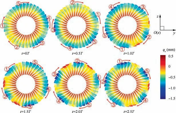
Fig.22 Displacements of shrouded blades based on rotational reference frame of rotor,blades’shapes are deformed 30 times greater for better view.
The frequency domain of the vibration of the shrouded and unshrouded blades is obtained by the FFT method. Fig. 25 shows the frequencies of the axial displacement of the tip of the blade. The green line is the result of the shrouded blades,in which three dominant frequencies are found, i.e., 1Ωs, 2Ωs,and 5Ωs. The 1Ωsand 2Ωsare the forced responses of the first-order and second-order excitations of the rotational stalled region. The frequency ratio of 5Ωs(3.52Ω) coincides the frequency of the 5BTW mode of the shrouded fan(f5BTW=3.57Ω), so the 5BTW mode is resonated by the fifth-order excitation of stalled flow. The 5BTW is activated because the its modal rotational speed coincides with the rotational speed of the stalled region. The magnitude of the resonated 5BTW mode is much larger than those of the two forced vibrations.
The red line is the result of the unshrouded blades,in which three major frequencies are also found,i.e.,1Ωs,2Ωs,and 4Ωs.The terms f1Band f1Tare the frequencies of the first-order Bending (1B) mode and the first-order Torsion (1T) mode of the unshrouded blades respectively. The frequencies of 2Ωs(1.37Ω) and 4Ωs(2.75Ω) are close to f1B(1.39Ω) and f1T(2.83Ω) respectively, so the 2Ωsis the 1B mode resonated by the second order excitation, and the 4Ωsis the 1T mode resonated by the fourth order excitation. The 2Ωsdominates the vibration of the unshrouded fan.The vibration magnitude of the unshrouded fan is much larger than that of the shrouded fan.That can be partly explained by the energy spectrum of the stalled flow: the intensity of 2nd excitation is much more strong than that of 5th excitation.
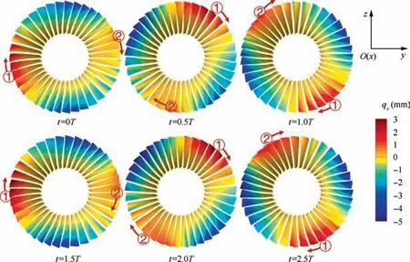
Fig. 23 Displacements of unshrouded blades based on rotational reference frame of rotor, blades’ shapes are deformed 5 times greater for better view.
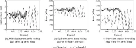
Fig. 24 Transient displacement and stress of a certain blade at rotating stall.
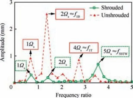
Fig. 25 Decomposed frequencies of axial displacements at rotating stall.
6. Discussion
6.1. Resonance map
By comparing the results of the shrouded and unshrouded fans, it can be concluded that a mode of annulus blades will be resonated at rotating stall when it meets the following conditions:
(1) Its frequency is an integer multiple of Ωs;
(2) Its rotational speed is equal to Ωs.
These two conditions are not independent for some modes.For any mode of the unshrouded annulus blades, whether Bending or Torsion type, its rotational speed is indefinite; in other words, it can be any value, as listed in Table 2, so it is exempted from Condition (ii). The rotational speeds of the Bending modes of the shrouded blades are infinite,so they cannot be resonated. For the nth order BTW mode of the shrouded blades, its frequency is n times the rotational speed,so, if Condition (ii) is met, Condition (i) is met automatically.Therefore, we only need to care about Condition (i) for the unshrouded blades, while for the shrouded blades, we only need to pay attention to Condition (ii).
The intensity of the resonance of different structural modes is different.The resonance of the 5BTW mode in the shrouded blades is much less violent than the resonance of the 1B mode in the unshrouded blades. This can be explained from two aspects:
(1) the structural and aerodynamic damping usually increases as the frequency of the response increases;
(2) the intensity of the excitation of the stalled flow is reduced as the order increases.
Therefore, the structural design of blades must avoid the resonance of the low order excitations.
Based on the discussion presented above,we have proposed a map to predict the resonance at a rotating stall, which we named as a ‘‘resonance map” in this paper. Fig. 26 shows the procedures to make the resonance map. The x-axis is the modal frequency, and the y-axis is the modal rotation speed.A point with the coordinates (f, Ω) means it has a frequency of f and a modal rotational speed of Ω. The detailed procedures are explained as follows:
(a) Choose a structural mode(named m mode,where m can be a number or a word to specify this mode) and plot a point at the map with the coordinate (fm,fm), where the fmis the frequency of this m mode;
(b) plot with the coordinate (fm, Ωm), where Ωm=fm/n, n can be any integer. The point at which Ωm=fm/n can be called the nth point of mode m. The symbol size of the point qualitatively represents the resonant intensity when the resonance occurs at this point, and it should be tapered as n increases,because the resonance at point(fm,fm/n)is activated by the nth order excitation,and the intensity of the excitation is reduced as the order increases.
(c) Fill the point with black color if the rotational speed can be achieved.As discussed above,the enabled(or achievable) rotational speed of a mode can be indefinite (any value), infinite, or a specific value, thus fill all if it’s indefinite, fill none if it’s infinite, and fill the specific point if it is a specific value.The filled points are named‘‘Enabled points,” while the unfilled points are called‘‘Disabled points.”
(d) Repeat the above procedures for other important modes. The symbol size should decrease as the modal frequency increases, because the high-frequency modes undergo more structural and fluid damping,so their resonant magnitudes tend to be smaller.
(e) Plot the line of the rotational speed of the stalled region Ωswith red color.
(f) Mark the enabled points with red color if they are crossed by the red line. These points are the resonated points. For a resonated point with the coordinate(fm,fm/n),it represents that the m mode with a frequency of fmis resonated by the nth order excitation, and the intensity of this resonance is qualitatively indicated by its symbol size.
6.2. Effects of the midspan shrouds on aeroelastic performance
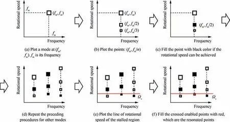
Fig. 26 Procedures for making a resonance map.
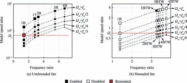
Fig. 27 Resonant map of unshrouded and shrouded fan.
The resonance maps of the shrouded and unshrouded fans is plotted in Fig.27.The map of the unshrouded fan is at subfigure (a), where all the points are marked as enabled. Two resonated points, i.e., the 1B mode with 2nd order excitation and the 1T mode with 4th order excitation, are found as expected. Subfigure (b) is the resonance map of the shrouded fan. All of the points of the 1B mode are disabled because the rotational speed of the 1B mode is infinite, thus there is no resonated point in the column of 1B mode even though the red line crosses the second point of the 1B mode. The 1st-5th BTW modes have a specific enabled value for each,and the red line crosses the 5th point of 5BTW.Since the intensity of the resonance is represented qualitatively by the size of the symbol,it can be derived from the map that the resonance of the 1B mode should be much stronger than that of the 1T and 5BTW modes.
Although the installation of midspan shrouds sacrifices a little aerodynamic performance and increases the centrifugal stress significantly, it controls the vibration of the blades at rotating stall. Resonance map provides a perspective to explain the effects of midspan shrouds at a theoretical level:the midspan shrouds make the rotational speed of a structural mode of the annulus blades change from an indefinite value to a settled value. Consequentially, the resonance map changes from Fig. 27(a) to Fig. 27(b), during which the enabled points are significantly reduced. The reduction of the enabled points will reduce the incidence of resonance and avoid the resonance of some modes, such as in-phase bending modes of the shrouded fan. Therefore, after the installation of midspan shrouds, the incidence and intensity of resonance decreases.
The resonance map has the ability to analyze the resonance at rotating stall, and it also can be used to design or optimize the structure of the midspan shrouds, as shown in Fig. 28. After the aerodynamic design is completed, a prototype of the fan is obtained, and the structural design and check ensue. The rotating stalled can be simulated by the unsteady CFD solver whether or not the fan is shrouded. The Ωs(rotational speed of the stalled region)and the intensity of each order excitation can be calculated.The modes of blades can be solved independently by the CSD solver. By combining the results of CFD and CSD,the resonance map can be drawn. The resonated mode,the corresponding order of excitation and qualitative intensity of resonance can be predicted by the map. Then, the configuration and position of the midspan can be adjusted,and the modes and frequencies of the new blades are updated by the CSD solver in the resonance map until the resonated point does not appear in the low-frequency and the low-order excitation region. The line of Ωsdoes not have to be recalculated because Ωsis not sensitive to the adjustment of the midspan shrouds. Finally, an optimized fan is obtained, and violent resonance is avoided. This design or optimization method avoid the coupled CFD/CSD simulation and only requires the CFD solver to execute once.Therefore, this method can be very efficient.
7. Conclusions
(1) At the designed state, the midspan shrouds slightly blocked the flow near the region of the midspan shrouds,and both the shrouded fan and unshrouded fan have stable aeroelasticity. The maximum stress on the unshrouded blades is much less than that on the shrouded blades due to the absence of the centrifugal load of the midspan shrouds.

Fig. 28 Procedures of designing or optimizing midspan shrouds by resonance map.
(2) When the rotating stall occurs,the stalled region rotates at 30% of the rotor speed on the absolute reference frame. The energy spectrum of the rotating stalled flow shows that the first two order excitations are much stronger than the higher order excitations.
(3) In the flow of rotating stall,the fifth backward travelling wave mode of shrouded blades is resonated by the fifth excitation of the stalled flow, because the rotational speed of the stalled region coincides with the modal rotational speed. However, for the unshrouded fan, the first bending mode is resonated by the second excitation of the stalled flow, forming two waves in the circumference of the annulus blades. At rotating stall, the vibration of the shrouded blades is still under control but the vibration of the unshrouded blades is diverged and out of control.
(4) A novel tool,named resonance map,is proposed to predict the resonance. It would be helpful in the structural design of blades, and It also provides a perspective to explain the effects of midspan shrouds: the modal rotational speeds of the annulus blades are changed from indefinite values to settled values after the installation of midspan shrouds,so the enabled points in the resonance map are reduced significantly.Consequentially,the incidence and intensity of resonance decrease considerably.
 CHINESE JOURNAL OF AERONAUTICS2020年2期
- CHINESE JOURNAL OF AERONAUTICS的其它文章
- Delaying stall of morphing wing by periodic trailing-edge deflection
- Optimization and verification of free flight separation similarity law in high-speed wind tunnel
- Non-intrusive reduced-order model for predicting transonic flow with varying geometries
- Consideration on aircraft tire spray when running on wet runways
- Experimental study on NOx emission correlation of fuel staged combustion in a LPP combustor at high pressure based on NO-chemiluminescence
- Research on nonlinear model predictive control for turboshaft engines based on double engines torques matching
