Consideration on aircraft tire spray when running on wet runways
Xinpeng ZHANG, Fei XU,*, Xunqi REN, Xingyng GAO,Rengng CAO
a School of Aeronautics, Northwestern Polytechnical University, Xi’an 710072, China
b Commercial Aircraft Corporation of China, Ltd., Shanghai 200126, China
KEYWORDS Aircraft tires;Engine ingestion;SPH;Spray pattern;Wet runway
Abstract The tire spray produced by aircraft running on wet runways may enter the intake of engines, which may lead to the compressor stall, surge, or even combustion flameout. Therefore, it is necessary to do some research work on the tire spray to help to solve this problem. Firstly, the mechanism of tire spray is analyzed,and some parameters are defined to describe the spray pattern.Secondly,the numerical model of tire spray is established by coupled Smoothed Particle Hydrodynamics (SPH) and Finite Element Method (FEM) in LS-DYNA software, and the model is validated by a simplified water spray experiment. Then some influence factors on the spray pattern are studied by numerical simulation. Finally, some suggestions are proposed on different types of aircraft to avoid too much tire spray being ingested into the engine intakes.
1. Introduction
When aircraft are taking off or landing on wet runways, the spray produced by tires may be ingested into the engine intakes. If the amount of the ingested water is too large, the jet engine may suffer from compressor stall, surge or even flameout. The commercial aircraft certification requires that an airplane may not ingest hazardous quantities of water or slush into engines and auxiliary power units during taxiing,taking off,and landing.1-4Therefore,researches on the aircraft tire spray are very necessary.
Studies on the tire spray can date back to the 1960s. In 1966, the NASA Langley Research Center conducted an experimental investigation to measure the flow rate and trajectory of water spray generated by an aircraft tire operating on a flooded runway.5,6Tests made use of a partial airframe and a nose tire from a general aviation aircraft. The effects of forward speed, tire load, and water depth were evaluated by measuring the amount and location of water captured by an array of tubes mounted behind the test tire. In 1970, Barrett from Bristol University established a model test facility to research the tire spray.7The principle of the test method was to run the model wheel on an endless belt onto the surface, of which a layer of water was ejected tangentially at the speed of the belt. In this way, the forward motion of a wheel on a fluid-covered runway was simulated.Through these experimental works, some basic understandings on the tire spray were established and the influence factors of spray pattern were researched preliminarily. In 1998, the 83042 document of Engineering Sciences Data Unit (ESDU) proposed an empirical method to predict the envelopes of tire spray based on a large number of experimental investigations.8,9This method gave an estimation of spray envelopes by defining the height,width,and location of the spray pattern.However,the spray location was only roughly predicted,and the accuracy of this empirical model strongly depended upon the test data.Besides,this method cannot predict the influence of spray suppression devices such as the spray deflectors and the chine tires.In 2013, Gooden from the National Aerospace Laboratory/NLR proposed the CR-spray method10which was based on the droplet trajectory calculations to predict the diffusion regions of tire spray. However, the initial conditions of these trajectories were based on the empirical relations from the ESDU. So the prediction results were still unreliable.
In recent years,the research method on tire spray is in transition from experiment to numerical simulation. The Smoothed Particle Hydrodynamics(SPH)method is a suitable particle method which is good at simulating large deformation and free surface problems and has been widely used in jet impingement, droplet collision and other related research fields.11-13Qu et al.14used SPH method to simulate the water spray caused by a single tire without chine at different taxiing speeds.In the meantime,Xu et al.15used SPH method to simulate the water spray generated by a chine tire. Zhao et al.16developed an integrated simulation platform that combines SPH and the Discrete Phase Model (DPM) in a finite volume framework to simulate the complex physical interactions and processes of tire spray.These numerical results show good consistence with the experiments.
The investigations above did a lot on finding influence factors and their effect laws on tire spray pattern. However, the mechanism of these factors had not yet been discussed deeply.These kinds of investigations cannot be expected to help much on the design of modern commercial aircraft.In this paper,the problem of tire spray is researched by numerical simulation.We focus on the initial stage of tire spray to analyze the essential influence factors on the spray pattern, which can provide supports for avoiding the water ingestion on commercial aircraft.
The contents of the paper are organized as follows.In Section 2, the mechanism of tire spray is analyzed, and some parameters are defined to describe the spray pattern.Section 3 introduces the numerical model of tire spray which is established by coupled SPH and FEM in LS-DYNA software,and the model is validated by a simplified water spray experiment.In Section 4,some influence factors on the spray pattern are researched by numerical simulation.Finally,Section 5 presents some suggestions on different types of aircraft to avoid too much tire spray being ingested into the engine intakes.
2. Description of tire spray
2.1. Physics of tire spray
According to the spray trajectory, tire spray can mainly be divided into two parts: the ‘‘bow wave” and the ‘‘side spray”,as shown in Fig. 1.17When an aircraft tire rolls on a wet runway, the water in the path of tire must be displaced when the tire velocity is below the hydroplaning speed. The majority of the water along the path is squeezed downward by the tire and displaced laterally. In this process, the side spray is formed.There is still a small amount of water that exits the tire path in a ‘‘bow wave”, which is displaced ahead of the tire. If the landing gear uses a kind of dual-wheel configuration,there will be another kind of spray generated between two wheels,which is named the‘‘rooster tail”.It is caused by the impingement of two side sprays on each other from closely spaced wheels.
2.2. Relative locations between spray patterns and aerodynamic geometries
Fig.2 shows the water spray test of the A350 XWB performed at Istres, France in May 2014.18It can be seen that the most obvious part of the spray comes from the side spray generated by the nose tires,which is also near the engines.Oppositely,the amount of bow wave is very small,and it is far away from the engines. So the bow wave has little chance to be ingested into the engines. Besides, the rooster tail generates under the fuselage and will be deflected not to splash toward the engines.Therefore, in this paper we just discuss the pattern of side spray generated by a single tire.
According to the characteristic of side spray,the spray pattern in the front view can be described by the front-view angle φ, as shown in the left side of Fig. 1. The spray pattern in the side view can be described by the side-view angle λ,as shown in the right side of Fig. 1.
According to a large number of full-scale aircraft spray test results, the spray patterns are roughly in a fixed region: the front-view spray angle is in the range of 40-60°and the sideview spray angle is in the range of 10-30°. So there exist aircraft which have fortunate aerodynamic geometries so that the engines can stay clear of tire spray.
Modern commercial aircraft mainly have two kinds of typical configurations: the rear mounted turbine driven aircraft and the wing mounted turbine driven aircraft, as shown in Fig. 3. For the rear mounted turbine driven aircraft, the moving paths of engines are usually across the tire spray region.There are two possible ways for the engines to stay away from the tire spray: to stay closer to the fuselage or to stay higher than the spray region. For the wing mounted turbine driven aircraft,the tire spray can pass through it between the fuselage and the engines,so the ingestion problem is not as severe as the rear mounted turbine driven aircraft.
2.3. Tire spray suppression devices

Fig. 1 Sketches of tire spray.17

Fig. 2 A350 XWB water spray test.18
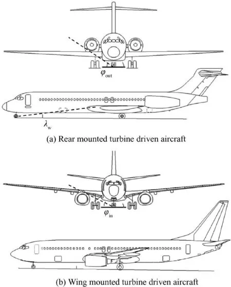
Fig. 3 Typical aircraft configurations.
There are some devices which are specifically designed for suppressing the tire spray, such as the spray deflector and the chine tire, as shown in Fig. 4. The metallic spray deflector is mounted on the axle of tire, which may bring some fatal risks during the aircraft taking off or landing.On the one hand,the spray deflector may get stuck with the door of landing gear,which may lead to the landing gear out of control. On the other hand, the spray deflector is so close to the ground that may impact the arresting system on the runway, which may produce fragments to threaten the flight security. In recent years, there were a large number of flight accidents caused by the spray deflectors.

Fig. 4 Tire spray suppression devices.
By contrast, the chine tire is made up of a rubber chine‘‘growing” on the sidewall of the tire. This kind of design can bring some benefits compared with the spray deflector.First of all, the security of chine tire is much better than the spray deflector. Secondly, it is easy to install. Furthermore,the rubber chine will bring less additional mass to the aircraft.
The suppression mechanisms of the spray deflector and the chine are almost the same,except that the spray deflector has a much larger influence range, which can bring better suppressing effectiveness. However, the fatal risks brought from the spray deflector threaten the flight safety even more than the spray itself. So the chine tire is a better choice in overall consideration.
3. Analysis of tire spray by numerical simulation
3.1. Establishment of tire spray model and its validation
To research the influence factors on the tire spray pattern, a more precise numerical model of tire spray compared with Ref. 15 is established by coupled SPH and FEM. The model is made up of a water pool in SPH and a tire in FEM.Because the effect of air in the initial stage of tire spray is negligible,it is not considered in the simulation. The improvements are mainly reflected in the initial distribution of the SPH particles and the mesh method of the tire.The scale of water pool in the numerical model in Ref. 15 is so large that the pitch between every two SPH particles is too large to approximate the water properties precisely. In this paper, the scale of water pool has been reduced sharply so that the particle pitch can be small enough to catch the details of tire spray. As for the mesh method of tire, Ref. 15 uses a kind of solid tire model, which has obvious disadvantages. On the one hand, the deformation of this model may be different from the real tire, which will directly influence the spray pattern. On the other hand, the phenomenon of hydroplaning cannot be considered because of the lack of tire pressure.In this paper,a model of pneumatic tire is established according to a real aircraft chine-tire configuration, as shown in Fig. 5. The structure of the tire model is simplified into 5 parts: hub, sidewall, tread, inner liner, and chine, as shown in Fig. 6. The deformation of the hub can be ignored, so this part is assigned with a rigid material. The thread and the sidewall use a kind of hyper-elastic material named MOONEY-RIVLIN rubber. The inner liner uses the elastic material.The deformation of this model can be adjusted to be consistent with the reality by changing the material properties of different parts. To simulate the tire pressure,0.53 MPa uniform pressure is loaded on the inner liner.
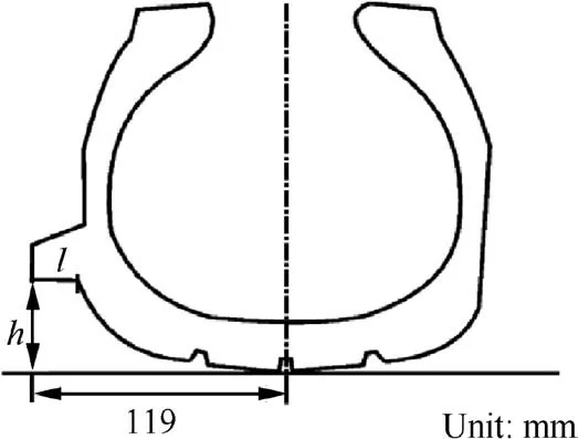
Fig. 5 Tire structure.
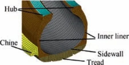
Fig. 6 Numerical model of tire.
The material property of water is simulated by combining a NULL material with a Gruneisen Equation Of State (EOS).The parameters are shown in Table 1.
3.2. Model validation
To validate the tire spray model, an experimental research of tire falling into water vertically was conducted, which was based on the similarity of tire rolling in the water and falling into water.19
The comparisons between the numerical result and the experimental result are shown in Figs. 7 and 8. It can be seen in Fig.7 that the size of tire footprint in the numerical result is approximately closed to the experimental result, which illustrates that the simulated tire deformation is consistent with the reality. The precision of the simulation by SPH method depends much on the particle pitch, so the independence of particle pitch must be considered. Different particle pitches of 4 mm, 2 mm and 1 mm have been tried in the tire spray model as shown in Fig. 8. It can be found that when the particle pitch is below 2 mm, the spray pattern tends to be stable and similar to the experimental result. So the particle pitch is intended to be 2 mm in this simulation.
Fig.8 illustrates that the numerical model can precisely simulate the initial spray pattern and the influence of chine.Therefore, this numerical model is credible in simulating the initial process of tire spray.
3.3. Model of aircraft tire spray and primary analysis
To simulate the real process of aircraft tire spray, some loads should be imposed on the tire model. First of all, 22 kN vertically downward force is loaded on the hub to simulate the tire load produced by the weight of aircraft. Then, a forward speed is imposed on the hub to simulate the taxiing speed.To make the tire roll on the ground,a kind of coulomb friction is set between the tire and the ground.
In the real aircraft spray test,the water pool should be large enough to confirm whether the engines can tolerate the water spray for a period of time or not.But in the numerical simulation,this kind of computation scale is unacceptable and unnecessary. According to the mechanism of tire spray, the side spray can be seen as the superposition of continuous lateral jet flow in the taxiing direction. Therefore, a small segment of the whole water pool can also get the spray pattern,so that the computation scale can be greatly reduced to an acceptable magnitude. To prove this point, simulations with different sizes of water pool have been conducted, as shown in Fig. 9.It can be seen that the pattern of side spray in the result of 400 mm×400 mm water pool is almost the same as that of 1 m×1 m water pool. Therefore, the size of 400 mm×400 mm for the water pool is confirmed large enough to get a stable spray pattern in this simulation.
It is discussed earlier that the spray pattern can be described by the front-view angle φ and the side-view angle λ. In the result of our simulation, the front-view spray angle can be measured directly. As for the side view, the water pool is not long enough to measure the side-view spray angle. However,as discussed before, the side spray is the superposition of continuous lateral jet flow which has little forward velocity,so the side-view spray angle λ can be approximately replaced by the arc tangent value of the ratio of vertical spray velocity to taxiing speed.
4. Influence factors on spray pattern
4.1. Influence of water depth
The water depth will influence the front-view spray pattern.As shown in Fig. 10, with the increase of water depth, the frontview spray angle φ increases first and then tends to a certain value. The commercial aircraft certification3requires that the airframe manufacturer should demonstrate the capability of an airplane operating on a runway with one half inch(12.7 mm) of standing water without experiencing any spray ingestion problem. So all the conditions when the water depth is under 12.7 mm must be considered at least.
4.2. Influence of taxiing speed
The change of taxiing speed mainly influences the side-view spray angle. ESDU found that the side-view spray angle increases first and then decreases with the increase of taxiing speed, but the reason had not been researched. As discussed before,the value of side-view spray angle depends on the ratio of the vertical spray velocity (vz) to the taxiing speed (v0). Asshown in Fig.11,with the increase of taxiing speed,the vertical spray velocity increases rapidly at first and then the increasing trend slows down. Moreover, as shown in Fig. 12, the tire would be lifted up due to the water pressure built around the tire under high taxiing speed,which is called the hydroplaning.In this condition, the contact area between tire and water will decrease, and the squeezing action between tire and water is decreasing too, which will lead to the decrease of the spray velocity. Therefore, the arc tangent value of the ratio of vertical spray velocity to taxiing speed increases first and then decreases, which represents the relationship between the taxiing speed and the side-view spray angle.

Table 1 Material parameters of water.
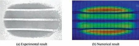
Fig. 7 Comparison of tire footprint.
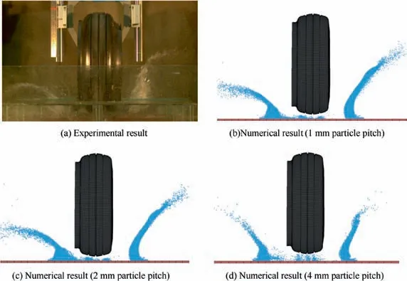
Fig. 8 Comparison of spray pattern.
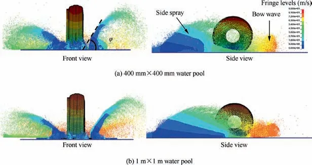
Fig. 9 Simulation result of tire rolling in water (color represents particle velocity).
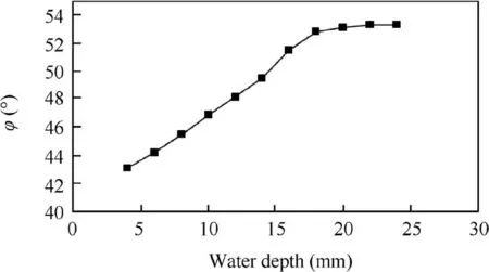
Fig. 10 Influence of water depth.
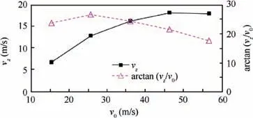
Fig. 11 Influence of taxiing speed.
4.3. Influence of tire configuration
The tire spray pattern in the front view depends mostly on the shape of the contact area between tire and water.As shown in the non-chine side of Fig. 13, the generating of tire spray can be divided into two processes. In the first process, the spray moves upward along the tire surface, and then in the second process it detaches from the tire. Therefore, the shape of tire section plays an important role in the generating of tire spray,20which can be roughly described by the sidewall angle φs. As shown in Fig. 14, the front-view angle of the spray will increase with the increase of φs.
4.4. Influence of chine tire
The chine tire is designed specifically for suppressing the tire spray as introduced before. The chine configuration is shown in Fig. 5, which can be described mainly by the width l and the height h. The suppressing effectiveness of chine mainly depends on the relative position between the chine and the water surface. Here we define the distance between the lower surface of the chine and the water surface as h′, as shown in Fig. 13(a), which is equal to the value of chine height minus that of water depth.When the value of h′is small,the effectiveness of chine is to decrease the front-view spray angle; when the value of h′is large, the effectiveness is to decrease the vertical spray velocity,so as to decrease the side-view spray angle,as shown in Fig. 15. The effectiveness comparison of different chine is shown in Fig. 16.
Fig.15(a)shows the velocity vector of water particles under the chine when the value of h′is small.The chine is so close to the surface of water that the particles have no space to splash freely.So most of the particles are deflected and the trajectories are changed to go outside horizontally,which then disturb the outside particles. In this way, the front-view spray angle has been decreased, as shown in Fig. 16(b).
Fig.15(b)shows the velocity vector of water particles under the chine when the value of h′is large.In this condition,only a small part of high-velocity particles are deflected and then go outside horizontally in the air without colliding with other particles. Because the tire has a forward speed, the low-velocity particles have no chance to contact with the chine.So the effect of this kind of chine is to decrease the vertical spray velocity,as the high-velocity part of the spray is deflected. The front-view spray angle almost has no change because the majority of spray has not been influenced by the chine, as shown in Fig.16(c).
To further analyze the influence of chine height h′on the spray suppression effectiveness, a series of simulations have been carried out with different chine height, and the result is shown in Fig.17.It can be found that the vertical spray velocity vzreaches the minimum value when h′is about 20 mm,and the front-view spray angle φ reaches the minimum value when the lower surface of chine is just on the water surface. So the best chine height to decrease the side-view spray angle is 20 mm from the water surface, whilst the best to decrease the front-view spray angle is just equal to the water depth.
When considering the chine width l,as the chine is close to the water surface, the initial water spray is deflected before it has an opportunity to spread apart laterally. So it is unnecessary to design a chine with a large cross-sectional area to deflect the initial water spray.For the tire model in this paper,30 mm of chine width is enough. A wider chine will not bring better effect.
5. Advice on aircraft design
After discussing about the tire spray pattern and its influence factors, some advice can be proposed to solve the problem of water ingestion when aircraft run on wet runways. First of all, aerodynamic designs to purposefully accomplish this end are the ideal. If it is difficult to avoid the water ingestion completely by optimizing the aerodynamic geometries, some improvement approaches on the tire configuration of nose landing gear can also be considered to change the spray patterns. Comprehensive advice on different types of aircraft will be discussed below.
5.1. For rear mounted turbine driven aircraft

Fig. 12 Phenomenon of hydroplaning.

Fig. 13 Generating of tire spray.
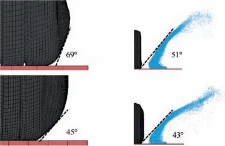
Fig. 14 Influence of φs on spray pattern.
For the rear mounted turbine driven aircraft,the tire spray can pass through it without being ingested into the engines by two ways:under the wings or outside the engines.Firstly,considering about the aerodynamic geometries,φoutand λwin Fig.3(a)are the main parameters to design for solving the water ingestion problem. According to the water spray region discussed before,when the value of φoutis larger than 60°(the maximum value of front-view spray angle) or the value of λwis larger than 30°(the maximum value of side-view spray angle),the tire spray has little chance to be ingested into the engines.But these purposes usually cannot be achieved by the obstacles from the consideration of either aerodynamic configuration or structure strength. Then some special designs can be used on the nose landing gear. As discussed before, tires with high chines can decrease the value of side-view spray angle λ by 5° to 10°,which can help make the spray pass through the aircraft under the wings. Tires with low chines can decrease the value of front-view spray angle φ by 5° to 10°, which can help make the spray pass through the aircraft outside the engines.Besides, using a non-chine tire with a small value of sidewall angle φscan also achieve the similar effect as a low-chine tire.
5.2. For wing mounted turbine driven aircraft
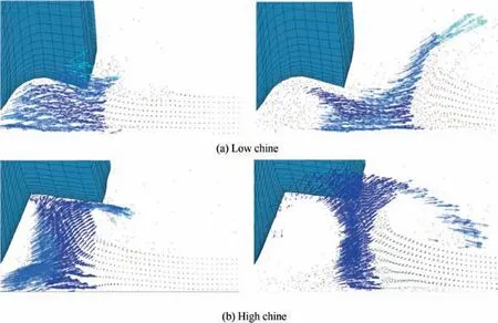
Fig. 15 Spray suppression mechanisms of different chines.

Fig. 16 Spray suppression effectiveness from different chines (color represents spray velocity).
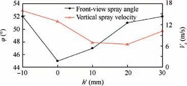
Fig. 17 Influence of chine height on spray suppression effectiveness.
For the wing mounted turbine driven aircraft, the tire spray can pass through it between the fuselage and the engines without being ingested into the engines. So the inside angle of the engine φinas shown in Fig.3(b)should be small enough to leave sufficient space for tire spray. In consideration of the design on the landing gear, a non-chine tire with a large value of sidewall angle φsis helpful to increase the value of frontview spray angle to make the spray region keep away from the engines.
6. Conclusions
The tire spray produced by aircraft running on wet runways has been researched by a numerical way of coupled SPH and FEM in LS-DYNA software. The accuracy of the numerical model is validated by a simplified water spray experiment.Then some influence factors on the spray pattern are researched. Major findings are:
· The value of front-view spray angle will increase first and then tend to be a certain value with the increase of the water depth.
· The value of side-view spray angle will increase first and then decrease with the increase of the taxiing speed.
· The value of front-view spray angle can be changed by 5°to 10°by designing the shape of the tire sidewall or designing a proper chine.
· The value of side-view spray angle can be changed by 5°to 10° by designing a proper chine.
According to these findings, some comprehensive suggestions about solving the problem of water ingestion on different types of aircraft are discussed:
For the rear mounted turbine driven aircraft,increasing the value of φoutin Fig.3(a)combined with using a low-chine tire or a non-chine tire with a small value of sidewall angle φscan help to make the tire spray pass through it outside the engines.Besides, increasing the value of λwin Fig. 3(a) combined with using a high-chine tire can help to make the tire spray pass through the aircraft under the wings,so that under the engines.
For the wing mounted turbine driven aircraft, decreasing the value of φinin Fig. 3(b) combined with using a nonchine tire with a large value of sidewall angle φscan help to make the tire spray pass through it between the fuselage and the engines.
Acknowledgments
This work was supported by the Aeronautical Science Foundation of China(No.2016ZD53038). The authors also acknowledge the support of the Commercial Aircraft Corporation of China Ltd.
 CHINESE JOURNAL OF AERONAUTICS2020年2期
- CHINESE JOURNAL OF AERONAUTICS的其它文章
- Delaying stall of morphing wing by periodic trailing-edge deflection
- Optimization and verification of free flight separation similarity law in high-speed wind tunnel
- Non-intrusive reduced-order model for predicting transonic flow with varying geometries
- Aeroelastic simulation of the first 1.5-stage aeroengine fan at rotating stall
- Experimental study on NOx emission correlation of fuel staged combustion in a LPP combustor at high pressure based on NO-chemiluminescence
- Research on nonlinear model predictive control for turboshaft engines based on double engines torques matching
