Non-intrusive reduced-order model for predicting transonic flow with varying geometries
Zhiwei SUN, Chen WANG, Yu ZHENG, Junqing BAI,*, Zheng LI,Qing XIA, Qiujun FU
a Research Institute of Unmanned Aerial Vehicle, Northwestern Polytechnical University, Xi’an 710072, China
b Science and Technology on Space Physics Laboratory, Beijing 100076, China
KEYWORDS Artificial Neural Network;Domain decomposition;Geometric parameters;Non-Intrusive Reduced-Order Model;Proper Orthogonal Decomposition;Transonic flow
Abstract A Non-Intrusive Reduced-Order Model(NIROM)based on Proper Orthogonal Decomposition(POD)has been proposed for predicting the flow fields of transonic airfoils with geometry parameters. To provide a better reduced-order subspace to approximate the real flow field, a domain decomposition method has been used to separate the hard-to-predict regions from the full field and POD has been adopted in the regions individually. An Artificial Neural Network (ANN)has replaced the Radial Basis Function (RBF) to interpolate the coefficients of the POD modes,aiming at improving the approximation accuracy of the NIROM for non-samples.When predicting the flow fields of transonic airfoils, the proposed NIROM has demonstrated a high performance.©2020 Chinese Society of Aeronautics and Astronautics.Production and hosting by Elsevier Ltd.This is an open access article under the CC BY-NC-ND license(http://creativecommons.org/licenses/by-nc-nd/4.0/).
1. Introduction
Reduced-Order Models (ROMs) have been developed and applied in many areas because of their high efficiency. There exist many kinds of ROMs, such as Proper Orthogonal Decomposition (POD),1Harmonic Balance (HB),2and Voltera Series.3Among these ROMs, POD-based ROMs (PODNIROMs) are the most widely used, since POD can deal with complex problems conveniently and its modes are optimal in the square sense. POD-ROMs first adopt POD to extract the optimal reduced modes in a square sense and then based on a variety of methods, determine the undetermined coefficients for the reduced modes. In the field of aerodynamic design,computations of many configurations are needed, which is time-consuming. If the results can be provided efficiently by building robust ROMs, it will bring a huge computational benefit.
Traditional POD-ROMs approximate the coefficients of the modes by solving ordinary differential equations derived from governing equations through the projection methods such as Galerkin Projection.4These methods rely on governing equations, thus belonging to Intrusive ROMs (IROMs). Li5and Yao6build POD-IROMs for not only state variables but adjoint variables in transonic flows, and then adopt them in gradient-based aerodynamic shape optimizations using adjoint methods. However, POD-IROMs depend on governing equations and numerical codes,leading to the fact that they cannot be applied when the source code is unavailable. On the other hand,aerodynamic designs always involve dozens of geometry parameters;however,POD-IROMs cannot be directly applied in transonic flows with many geometry parameters.To address these concerns,Non-Intrusive ROMs(NIROMs)which do not rely on governing equations are studied.POD-NIROMs build the mapping relationship between the mode coefficients and design parameters with interpolation methods, which do not refer to the governing equations. Xiao7and Chen8both use Taylor series expansion to build nonlinear POD-NIROMs.Peherstorfer and Willcox9constructs a nonlinear ordinary differential equation between state variables and input parameters, and then solves the reduced models by the least square method. Xiao7points out that the computational cost of non-intrusive methods will increase exponentially with the increase of design parameter dimension. After that, they propose a highly efficient POD-NIROM for high-dimensional parameter problems based on a sparse grid method. In addition to the above methods, researchers couple POD with non-linear interpolation methods such as Radial Basis Function (RBF),10,11Kriging model12,13and Artificial Neural Network (ANN) to build POD-NIROM, which are called PODRBF, POD-Kriging and POD-ANN respectively. As RBF is flexible, convenient and accurate in approximating discrete functions, POD-RBF has been widely used in different fields and satisfactory results have been obtained: Walton et al.14uses POD-RBF to accurately predict the unsteady flow field of ONERA M6 wing under oscillating conditions; Zhang et al.15,16applies this method to practical problems such as buffeting, and finds that the approximation accuracy of the limit cycle could be significantly improved by using multiple kernels. POD-Kriging is mainly used in aerodynamic shape optimization.17-19To compare the advantages and disadvantages of POD-RBF and POD-Kriging, Zimmermann and Goertz20uses both models to predict the transonic steady flow field of NACA64A010 airfoils and NASA’s Common Research Model (CRM)21respectively. By comparison, Zimmermann finds that the accuracy of the two models is equal,and the computational cost of predicting the flow field is much less than that of Computational Fluid Dynamics (CFD)numerical simulation. Qiu et al.22also compares PODKriging and POD-RBF in subsonic and transonic steady flow of airfoil, and concludes that the accuracy of POD-RBF is a slightly higher than that of POD-Kriging. In recent years,research on POD-ANN has gained more attention23-26because of its nonlinear feature.
Researchers adopt the above methods in aerodynamic shape optimization design17-19and inverse design.27-29However, to the authors’ knowledge, the application of PODNIROM in transonic aerodynamic designs is still limited because of the low accuracy. Both Iuliano and Quagliarella17and Zhang30et al. indicate that POD-NIROM cannot predict transonic flow fields accurately, particularly in regions of shock waves.The main reason is that POD essentially belongs to linear methods,as Holmes states that‘‘linearity is the source of the POD method’s strengths as well as its limitations”.Furthermore, the non-intrusive feature also brings more difficulties in accurately predicting transonic flows, as the NIROMs ignore the useful information provided by the governing equations.This paper aims to propose a NIROM,which is applicable to the prediction of transonic flows with geometry parameters. The NIROM employs a POD to extract spatial modes and ANN to estimate undetermined coefficients of the reduced basis.Different from other POD-NIROMs,the model in this paper adopts a domain decomposition method to separate the hard-to-predict regions from the whole flow field,and builds a NIROM for each domain individually. The structure of this paper is organized as follows. In Section 2, a transonic problem of airfoils is constructed. Afterwards, a POD-based NIROM is proposed in Section 3, which consists of POD,domain decomposition and ANN. This sets the stage for Section 4 where the performance of the present NIROM is confirmed by the prediction of transonic flow fields of the airfoils. Finally, Section 5 lists concluding remarks as well as prospects for future work.
2. Problem establishment
In this section, a transonic airfoil problem with seven geometrically related design variables is established. The mapping relationship between the design parameters and the airfoil shape is constructed by a geometric parametrization method.The calculated state is fixed to the wind tunnel test state of the RAE2822 airfoil: Mach number 0.725, Reynolds number 6.2 million, and angle of attack 2.72°. The geometric parametrization method and the full-order model are introduced respectively in this section.
2.1. Geometric parametrization method
In this paper, the Class and Shape Transformation (CST)parametrization method is adopted. It is a smooth and robust parametrization method proposed by Kulfan.31Its main idea is to shape the upper and lower surfaces of airfoils respectively with class functions and shape functions. Take the upper surface of the airfoil as an example. The airfoil shapeyupperis expressed by CST as:


Supper(x ) denotes the shape function:

where θ = {θ1,θ2,···,θ3}are the design variables.
For any θ,the corresponding geometric shape is determined by Eq. (1). In this paper, an RAE2822 airfoil with 1 m chord length is selected as the reference airfoil. The range of the design variables are all set to-0.1 ≤θi≤0.1.Five design variables are located on the upper surface of the airfoil and two on the lower surface of the airfoil.
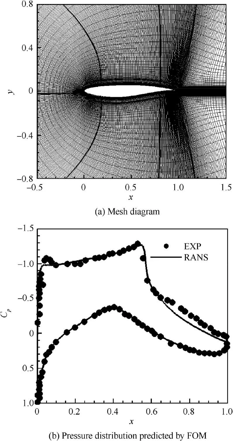
Fig. 1 Computational mesh and pressure distribution predicted by FOM.
2.2. Full-order model
Cfl3d from NASA, a finite volume solver based on Reynolds-Averaged Navier-Stokes (RANS) equations is chosen as the Full-Order Method (FOM). The grid topology is presented in Fig. 1(a), and the total grid size is about 100,000. To validate the accuracy of the FOM, the pressure coefficient Cpdistribution of the reference airfoil RAE2822 is predicted under computational conditions, as shown in Fig. 1(b). By comparing with the experiment result,the FOM can accurately predict the pressure coefficient distribution of RAE2822 with high reliability.
3.1. Basis extraction based on POD
POD-based NIROM aims to extract typical optimal reduced modes in a least square sense,and the solution vθ(x )is approximated by

where Φk(x ) (k=1,2,···,K) represents the typical modes extracted by POD, which are unit orthogonal, and ak(θ )denotes the undetermined coefficients of the kth reduced modes. Before applying POD, snapshots are firstly provided,denoted by vi(x ) (i=1,2,···,n). v0(x ) is given by the mean of the snapshots:

To extract the optimal modes, the approximation meets a minimization problem:


By introducing Eq. (4), problem (7) is transformed to a maximum problem of the shift snapshotsand reduced
modes Φi( x):

Based on Fredholm Theorem, the optimization problem turns into a problem of solving eigenvalues for the correlation matrix M, whose elements are computed by

As M is symmetric positive semi-definite,there exist N nonnegative eigenvalues denoted by λi(i=1,2,···,n). Define vv (x ) as the corresponding eigenvector. Then the relative reduced basis function can be determined by

From the mathematical derivation,the‘‘energy”of the system can be computed by

3. Establishment of POD-NIROM
In this section, a NIROM consisting of POD and ANN is adopted to predict transonic flows. POD is used to extract the reduced basis, while ANN is employed to approximate undetermined coefficients of the reduced basis. Moreover, in order to provide a better reduced subspace, a domain decomposition is introduced.
Thus, eigenvalues represent the degrees to which the relative reduced modes represent the ordinary system. To select proper modes, the eigenvalues are arranged in a descending order and truncated by a threshold 0 <ε <1:

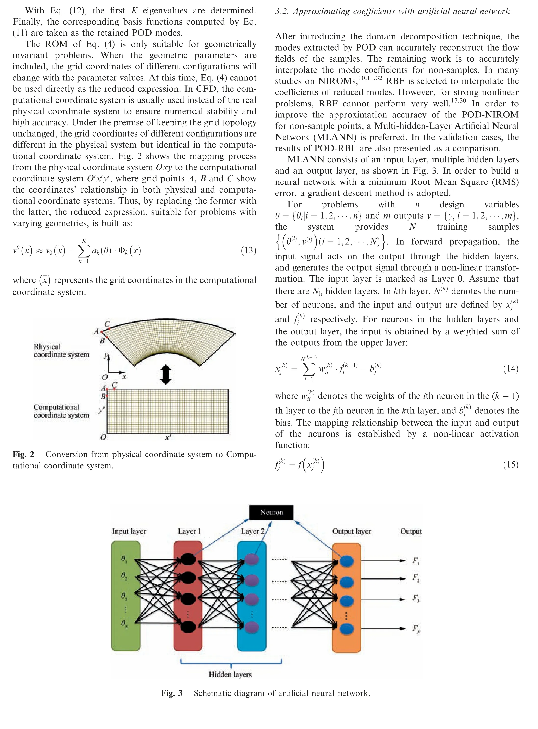
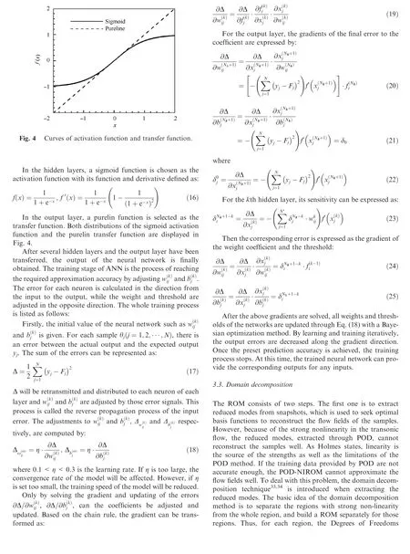

However,when using the domain decomposition method to predict the flow field,there will be a large gradient at the region boundaries.This is because different ROMs are applied to the prediction of the flow field in different regions. To deal with this problem, a smooth transition method is proposed in this paper: Firstly, a priority for each region is set. For the transonic flow, the region with shock wave is given by the highest priority, and the region near the leading edge of the airfoil is the second in priority.Starting from the region with higher priority,the low priority region in its adjacent region is smoothed.The points between the boundary point of the higher priority region and the third interior point of the lower priority region are interpolated with a Hermite interpolation polynomial.The boundary point of the higher priority region is marked by x0and the third interior point of the lower priority region is marked by x1. The derivatives of the state variables at both points are defined by vx0and vx1respectively. Then the interior points are smoothed by

where l0(x ) and l1(x ) represent Lagrange interpolation basis functions:

3.4. Summary of proposed ROM
The whole process of the proposed NIROM is summarized in Fig.5.The two purse solid squares in Fig.5 mark the two key techniques of the method, the domain decomposition and ANN, respectively.
4. Numerical test-case
In this section, the POD-NIROM proposed in Section III is established to approximate the transonic flow fields of the airfoils built in Section 2. By the Latin hypercube method,35500 samples are randomly selected in the design space. To ensure that the whole fitting process is interpolated, all vertices in the parameter space are added to the sample points. Thus, a total of 628 samples are determined.Then with a moving grid,the computational grid of each sample is generated from the reference grid in Fig.1.Above all,the whole process of generating the flow fields at unknown points by the FOM or PODNIROM is listed in Fig. 6.
4.1. Prediction of surface pressure distribution
As presented in Section 3, POD cannot reconstruct the flow fields of the samples very well because of the nonlinear structures, thus this paper adopts the domain decomposition technique. For transonic airfoils, the hard-to-predict regions are the ones around the shock and the leading edge of the airfoils.Based on this, the whole flow field is divided into three zones,as shown in Fig.7:Zone 1 is a grid block in the middle region of the upper surface the airfoil,where shock waves are located;Zone 2 is the grid block at the leading edge of the lower surface;the other regions of the flow field are denoted as Zone 3.
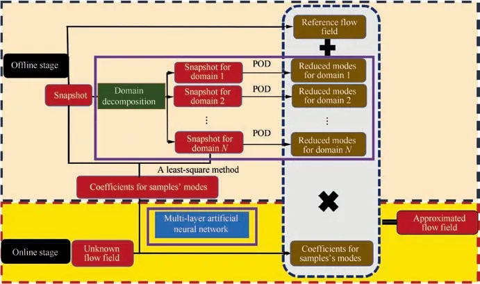
Fig. 5 Schematic diagram of the proposed NIROM.
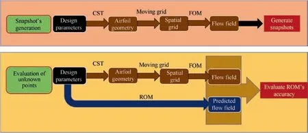
Fig. 6 Schematic diagram of generating the flow fields at snapshots and unknown points.
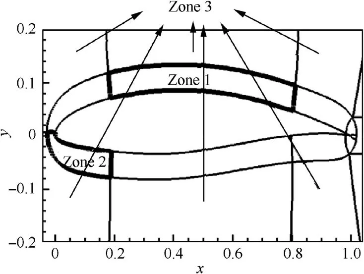
Fig. 7 Schematic diagram of domain decomposition.

Table 1 Computation complexity in extraction of temporal modes for complex problems.
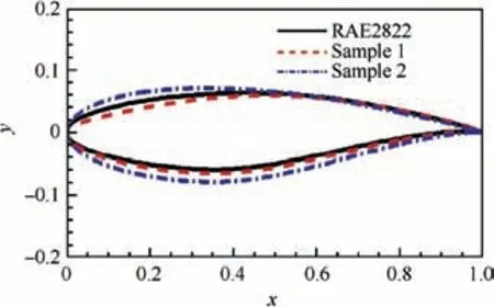
Fig. 8 Shape of two sample foils.
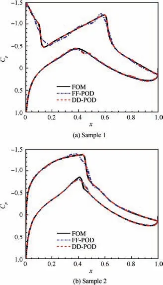
Fig.9 Comparison of pressure coefficient distribution predicted by FOM, FF-POD, and DD-POD for two samples.
Without using the domain decomposition, the threshold should be set to 0.999 to maintain a high mean accuracy,and then 34 eigenmodes are extracted by POD. When the domain decomposition is adopted, the thresholds of the other two regions can be set to 0.99 except Zone 1.The POD energy thresholds and the number of extracted modes in each region are listed in Table 1.Two airfoils are selected from the sample set and their geometries are shown in Fig. 8. Fig. 9 compares the pressure coefficient distribution of the samples, which is reconstructed by POD in the whole flow field as well as that of the domain decomposition, marked by FF-POD and DDPOD respectively. Clearly, the reconstructed results of POD modes are not accurate enough in the areas of shock and the leading edge of the airfoils.Compared with FF-POD,the pressure coefficients reconstructed by DD-POD can accurately simulate those hard-to-predict areas (see Fig. 9(a) and (b)).To further illustrate the advantages of the domain decomposition method, we keep the mode number of DD-POD unchanged and increase the modes of FF-POD. When the mode number of FF-POD increases from 34 to 55, the accuracy of the FF-POD in reconstructing the surface pressure coefficient distributions of the samples can be as high as that of DD-POD. However, at this time the DOFs of DD-POD is 39 (see Table 1), while that of FF-POD is 55. Therefore,when the computational efficiency and the reconstruction accuracy of the samples are considered, the DD-POD is superior to the FF-POD.
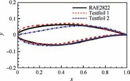
Fig. 10 Shapes of two testfoils.
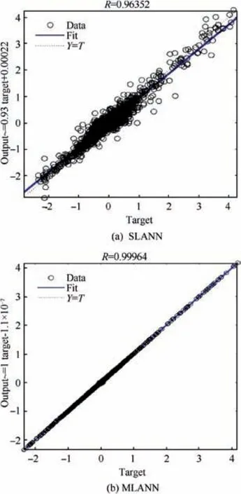
Fig. 11 Comparison of regression curves.
After a satisfying reduced subspace is built, the remaining work is to predict the pressure distribution of the nonsample testfoils, which is much more challenging. By combining the domain decomposition with POD, the training data provided by POD is accurate enough. As a result, the prediction effect for non-samples only depends on the interpolation method for determining the coefficients of the reduced modes.In this paper, the improved NIROM adopts a three-hiddenlayer ANN rather than RBF. Two non-sample testfoils are selected as shown in Fig.10.In order to show the fitting effect of the Multi-hidden-Layer ANN (MLANN), a comparison of Single-Layer ANN (SLANN) and three-layer ANN (denoted by MLANN) is conducted in Figs. 11 and 12. Fig. 11 shows the regression curves of SLANN and MLANN respectively,reflecting the difference between the prediction and the real output. In the figures, R denotes goodness of fit. The closer to 1R is,the higher approximation accuracy the ANN reaches.As shown in the figure,the training points of the MLANN are almost concentrated on Y=T, thus MLANN presents a higher accuracy. Fig. 13 lists the RMS error of the two methods. After training, the error RMS of MLANN is 10-4, while that of SLANN is 10-2. From Figs. 11 and 12, it can be seen that MLANN is more accurate than SLANN when fitting the training data.And then MLANN is used to compute the coefficients of the modes.Fig.13 compares the pressure coefficient distribution of the testfoils predicted by FOM,ANN-NIROM and RBF-NIROM. RBF-NIROM cannot predict the flow very well, and even if the number of modes is increased, the prediction effect is still limited, while ANN-based NIROM is more accurate in simulating the surface pressure coefficient distributions of the testfoils. However, it is worth noting that the model is still not robust in the parameter domain and there is still room for further improvement.
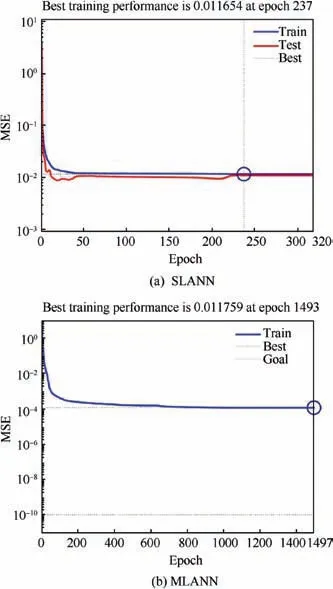
Fig. 12 Comparison of prediction accuracy between SLANN and MLANN.
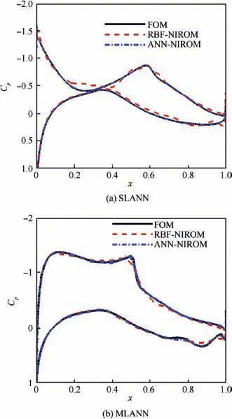
Fig. 13 Comparison of pressure coefficient distribution predicted by FOM, RBF-NIROM, and ANN-NIROM for two testfoils.
4.2. Prediction of flow fields
In Section 4.1,only the surface pressure coefficient distribution is modeled.In this section,the improved POD-NIROM is used to predict the whole flow field around the airfoils.In addition,approximations of the old NIROM consisting of POD and RBF are considered as a comparison. At this time, four state variables should be considered, including the density (ρ), xvelocity (u), y-velocity (v) and pressure (p). For NIROMs, it is preferred to build a NIROM for each state variable simultaneously.The detailed reason is presented in Ref.20.Therefore,this paper builds 4 POD-NIROMs to predict the flow field.
First of all, based on the domain decomposition, the improved POD-NIROM divides the flow field, in almost the same way as that of Section 4.1. The only difference is the scope of Zone I.Fig.14(a)shows the shock position of Sample 1 through a shock indicator function defined by Fshock=v·∇p/ (a·∇p ) (a denotes the sonic speed and ∇p denotes the pressure gradient).Clearly,the shock exceeds Zone I in Section 4.1. Therefore, Zone 1 is extended as shown in Fig. 14(b). A threshold of 0.999 is set for Zone 1, and 0.99 is set for Zones 2 and 3. After extracting the eigenvalues and arranging them in a descending order, the number of modes selected by each region is listed in Table 2. The old POD-NIROM takes the flow field as a whole, and the threshold should be set to 0.999.
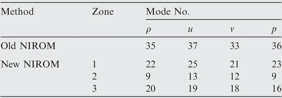
Table 2 Computation complexity in extraction of temporal modes for complex problems.
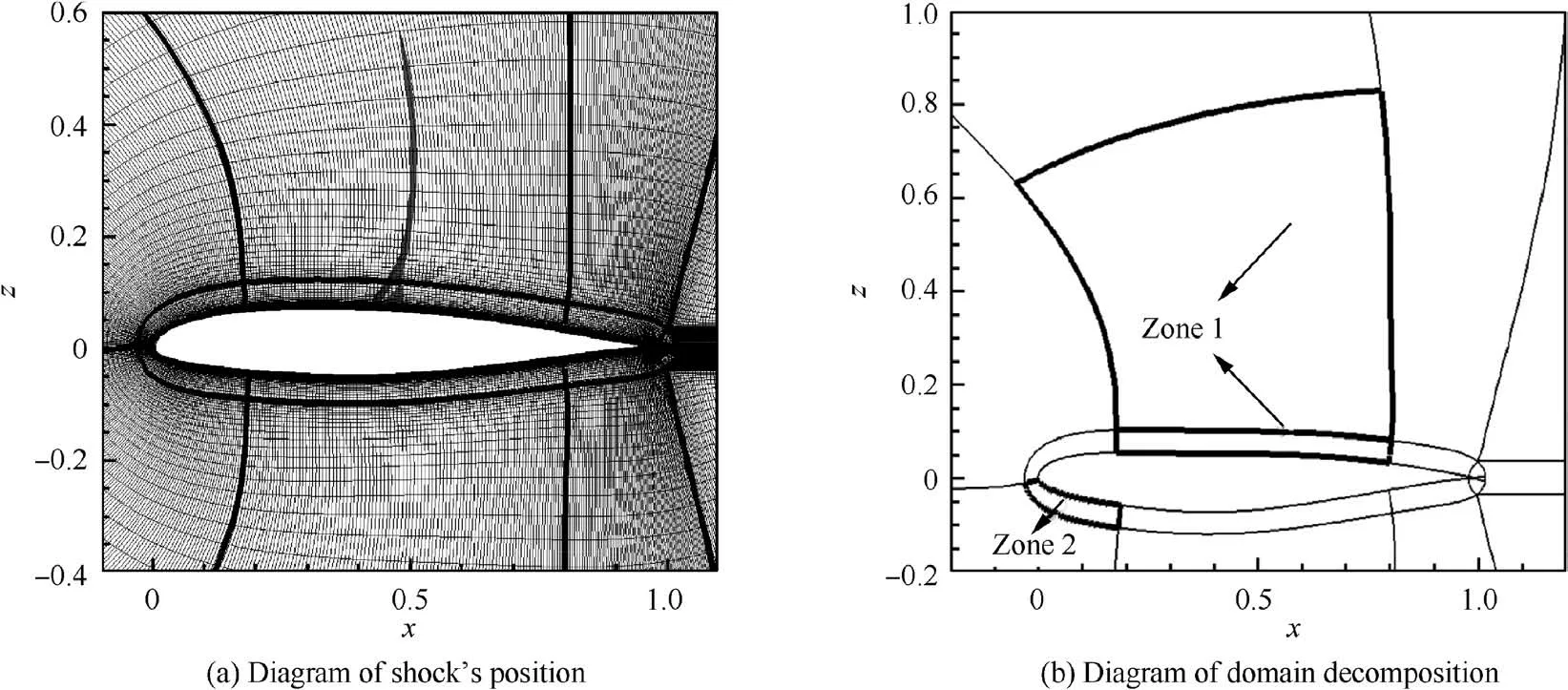
Fig. 14 Diagram of domain decomposition for full fields.
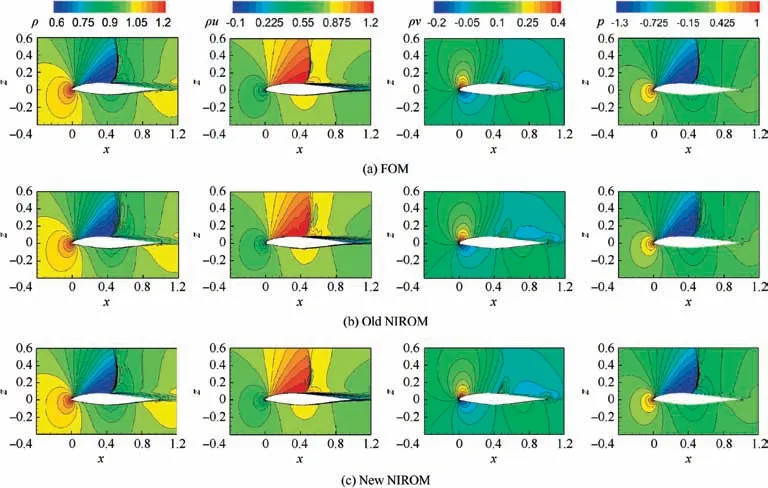
Fig. 15 State variables’ distributions predicted by FOM, old NIROM, new NIROM for Testfoil 1.
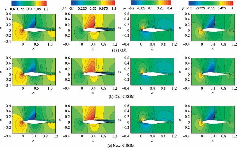
Fig. 16 State variables’ distributions predicted by FOM, old NIROM, new NIROM for Testfoil 2.
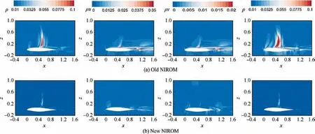
Fig. 17 Comparison of error distribution predicted by old NIROM and new NIROM for Testfoil 1.
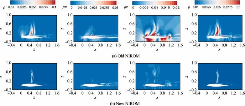
Fig. 18 Comparison of error distribution predicted by old NIROM and new NIROM for Testfoil 2.
The POD-NIROM is used to predict the transonic flow field of the two testfoils. It is worth noting that the state variables considered in this section are all non-dimensional. The distribution of the state variables is shown in Figs. 15 and 16, respectively. From the figures, it can be seen that the contour predicted by the improved NIROM is closer to the result of FOM than to that of the old NIROM. From the point of view of ρ and p, the improved model can even clearly capture the shock structures. Figs. 17 and 18 show the absolute error distribution between the flow field predicted by the two NIROMs and that of FOM.The old NIROM’s error of ρ and p is about 0.1 near the shock, and the velocity error is relatively large near the trailing edge of the airfoil, while the errors of the improved NIROM are small in the whole computational domain,in the order of 10-2.By evaluating the predicted flow field, the improved POD-NIROM can predict the transonic flow field more accurately.
When the geometry change is large,we admit that the accuracy of the ROM will be largely affected. However, it is still possible to accurately predict the geometry,when the following conditions are satisfied: (A) the parameter domain should include the geometry with considerable changes; (B) more snapshots should be provided;(C)when the geometry changes considerably, the problem becomes more nonlinear and the MLANN should be adjusted to correctly predict the flow fields.
5. Conclusions
This paper has presented a NIROM for predicting transonic flows. A reduced expression is first constructed for problems with varying geometries by replacing physical coordinates with computational coordinates. Then, to improve the accuracy of the NIROM for the prediction of transonic flows, a PODNIROM for transonic flows is established by coupling the domain decomposition and ANN.The domain decomposition technique provides a better reduced order subspace for POD,and improves the reconstruction accuracy in predicting the flow fields of the samples.In addition,for the sake of removing the large gradients at region boundaries, a smooth transition method based on Hermite interpolation polynomial is proposed. When approximating the mode coefficients, ANN with multiple hidden layers is adopted rather than RBF, thus improving the accuracy in approximating non-sample flow fields.
Future work should seek to improve the NIROM’s robustness in the whole parameter domain, possibly through the use of a local reduced basis and deep learning. This approach is also expected to be adopted in aerodynamic optimization by combining the NIROM with the adjoint method.
Acknowledgement
This work was supported by the National Natural Science Foundation of China (No. 11802245).
 CHINESE JOURNAL OF AERONAUTICS2020年2期
- CHINESE JOURNAL OF AERONAUTICS的其它文章
- Delaying stall of morphing wing by periodic trailing-edge deflection
- Optimization and verification of free flight separation similarity law in high-speed wind tunnel
- Consideration on aircraft tire spray when running on wet runways
- Aeroelastic simulation of the first 1.5-stage aeroengine fan at rotating stall
- Experimental study on NOx emission correlation of fuel staged combustion in a LPP combustor at high pressure based on NO-chemiluminescence
- Research on nonlinear model predictive control for turboshaft engines based on double engines torques matching
