Five-axis flank milling tool path generation with curvature continuity and smooth cutting force for pockets
Changqing LIU, Yingguang LI, Xin JIANG, Wenyao SHAO
College of Mechanical and Electrical Engineering, Nanjing University of Aeronautics and Astronautics, Nanjing 210016, China
KEYWORDS Curvature continuity;Cutting force;Five-axis flank milling;Machining;Tool path generation
Abstract In order to ensure machining stability,curvature continuity and smooth cutting force are very important so as to meet the constraints of both cutting force and kinematics of machine tools.For five-axis flank milling,it is difficult to meet both of the constraints because tool path points and tool axis vectors interact with each other. In this paper, multiple relationships between tool path points and tool axis vectors with cutting force and kinematics of machine tools are established,and the strategies of corner-looping milling and clothoidal spirals are combined so as to find feasible solutions under both of the constraints.Tool path parameters are iterated by considering the maximum cutting force and the feasible range of the tool axis vector, and eventually a curvature continuity five-axis flank milling tool path with smooth cutting force is generated. Machining experimental results show that the conditions of cutting force are satisfied,vibration during the process of machining is reduced, and the machining quality of the surface is improved.
1. Introduction
Complex structural parts of aircraft have high aerodynamic shape requirements,and pockets along the contours of aircraft structural parts are comprised of complex freedom surfaces,so five-axis flank milling is required.1The roughness requirements of pockets are generally at least 3.2 μm after milling. As tool radial and axial cutting depths are continuously changing during the cutting process in corner areas, and the material to be removed is not even,the cutting force may increase suddenly in a corner,which may speed up cutting tool wear,and even lead to cutting tool breakage.Meanwhile,the feed rate and rotation angle in the corner are continuously changing, while acceleration and angular acceleration are suddenly changed, which may result in poor surface quality and machining accuracy.
In order to ensure machining quality, curvature continuity and smooth cutting force are very important so as to meet both the constraints of cutting force and kinematics of machine tools. Tool path is a very import aspect to satisfy the constraints.2,3In this paper, a tool path generation method for five-axis flank milling of pockets by considering both the constraints of cutting force and kinematics of machine tools is proposed.Multiple relationships between tool path points and tool axis vectors with cutting force and kinematics of machine tools are established, strategies of corner-looping milling and clothoidal spirals are combined so as to find feasible solutions under the constraints, parameters are iterated by considering the maximum cutting force and the range of the tool axis vector, and eventually a curvature continuity five-axis flank milling tool path with smooth cutting force is generated.
2. Related work
In order to obtain good machining quality and machining efficiency of surfaces by five-axis flank milling for pockets, the research community has made many efforts,which can be classified into three categories:(1)tool path optimization considering cutting force, (2) tool path optimization considering kinematics of machine tools, and (3) tool path optimization considering both cutting force and kinematics of machine tools.
Tool path optimization considering cutting force aims at stabilizing cutting force.Erkorkmaz et al.4proposed a method to control the cutting force by optimizing the speed, acceleration, and acceleration jerk in the machining process. Cornerlooping milling is a common strategy to solve the unevenness of corner materials, which is used to remove materials with some loops at a corner so as to ensure the stability of the cutting force.Choy and Chan5,6introduced a tool path generation algorithm based on the corner-looping strategy which could greatly reduce the radial cutting depth of each tool path and the cutting force in a corner machining process.Banerjee et al.7developed a method to calculate the maximum radial cutting depth and the minimum number of loops,and an existing tool path algorithm based on corner-looping milling was improved by reducing the tool path length.Rahman and Feng8proposed an optimization method for corner-looping milling,and a constant material removal rate in the process was used to control the cutting force. Wu et al.9,10introduced a method to optimize the cutting force of a pocket with a sharp corner by using cycling transitional arc.
Research of tool path optimization by considering kinematics of machine tools aims at achieving the continuity of tool path curvature. In order to smooth the tool path curve, Zhao et al.11proposed a method of generating a tool path curve based on the double arc theory for sharp corners in pockets.Yao and Joneja12developed a method of generating a smooth tool path by using a combination of Archimedes and clothoidal spirals. Lin et al.13introduced a method to divide a machining area into a spiral tool path with continuous curvature and adjust the tool path to eliminate the residual area during the process in high-speed machining. Shi et al.14presented a method to analyze the connection at a corner, and smooth transition of a tool path curve at the corner was realized by using a five-time PH curve. Yang et al.15proposed an offline and on-line planning method to smooth corner tool paths,where seven-order spline curves were generated at the off-line stage,and then the tool paths were adjusted at the online stage in real time to achieve continuous curvatures of tool paths at the corner. In order to smooth the tool axis vector, Geng and Zhang16developed a method to avoid an abrupt change of the tool axis vector by restraining the difference between adjacent discrete tool axis vectors.Tulsyan and Altintas17proposed a seven-order B-spline curve to fit a discrete tool axis vector,and the Newton iteration method was used to generate continuously-varying tool axis vectors.Lin et al.18,19proposed to converse a tool axis vector to a machine structure space so as to avoid the occurrence of singularity effectively.Lu et al.20proposed that a spline curve could be used to fit the rotation angle of a tool axis vector to smooth the movement of the machine axis. By considering both the cutter location point and the tool axis vector, Lu et al.21developed a method of using the cutter location point error as a constraint, and used a gradient-based differential evolution method to generate a smooth five-axis flank milling tool path.Bi et al.22,23presented a method of generating a five-axis tool path based on the double Be´zier curve;meanwhile,the Be´zier curve was used to optimize the trajectories of the two ends of the tool axis.Li et al.24proposed a path generation method of onsite 5-axis surface inspection, where dual-cubic NURBS curves were used to respectively determine path points and axis vectors in an inspection path,and a smooth and non-interference inspection path was obtained. Huang et al.25proposed a 5-axis flank milling regeneration method for flexible thin-walled parts according to on-machine measurement data, where a 5-axis tool path was smoothed by an iterative process of tool position and rotation.
Some papers put efforts on tool path optimization by considering both cutting force and kinematics of machine tools.Xu et al.26proposed a five-axis flank milling tool path generation method for a blade cutting process considering the cutting force and machine tool kinematics, but this method still has some limitations on pocket machining. Xu et al.27introduced a spiral tool path planning method based on grid mapping for a 2.5D pocket,which could ensure the cutting force change within a certain range on the basis of satisfying the continuity of the tool path. Gao et al.28proposed an integrated machining process and a corresponding tool path generation algorithm for corners and sidewalls in aircraft structural parts,where corner looping was adopted so as to control the cutting force. Sui et al.29presented a method to achieve second-order continuity of tool paths by using the corner-looping milling strategy, and this work was part of the research of their team,where 3-axis flank milling of pockets has been focused. For 5-axis flank milling of pockets, their team has also made some efforts and proposed an initial idea,30but there is still much room for further research and development.In some commercial CAM software tools,such as HypermillTM,researchers also developed optimized tool paths for corner milling, but they still focused on rough machining with 3 axes (hyperMILL,http://www.openmind-tech.com/en/cam.html.).
Although the studies reviewed above have made many achievements,a tool path generation method of five-axis flank milling for pockets by considering both the cutting force and kinematics of machine tools should still be intensively focused.The difficulty to meet the constraints lies in that tool path points and tool axis vectors both have impacts on the changes of cutting force and the kinematics of machine tools,and a cutter location point and a tool axis are constrained with each other. To address the issue mentioned above, a new tool path generation method for five-axis flank milling of pockets will be studied in this paper.
3. Fundamentals of tool path generation for five-axis flank milling of pockets
During a milling process of pockets,the cutting force is mainly related to the contact angle of the cutting tool, and the kinematics of the machine tool is mainly related to the tool path curvature.In this perspective of view,the relationship between the cutting force and the contact angle of the cutting tool,and the relationship between the kinematics of the machine tool and the tool path curvature, are established firstly.
During a five-axis flank milling process, the instantaneous cutting thickness and the contact angle of the cutting tool are continuously changing due to tool axis vector changes and uneven remained material. In order to predict the cutting force more accurately and efficiently during a machining process of five-axis flank milling, the contact surface between the cutting tool and the workpiece is divided into N layers along the axis,and the tool contact angle and the instantaneous cutting thickness of the j-th spiral tooth of the i-th layer can be determined according to the machining residual model.In this paper,the method studied by Zhang et al.31for solving the tool contact angle and the instantaneous cutting thickness in a process of five-axis flank milling is used,and the cutting force prediction model of five-axis flank milling is established. The cutting force is derived and represented as follows:tics. In this paper, the movement of each axis is analyzed.Then, the movement characteristics of each axis are analyzed,and the relationship between the kinematics of machine tools and the tool path curvature as well as the tool axis vector is established. The tool position curve and the tool axis vector can be optimized according to the kinetic characteristics of the feed axis. Smooth movements of the translational axis and the rotating axis can reduce the vibration of the machine tool and improve the machining quality.
A CNC machine tool includes translational and rotary axes, as shown in Fig. 1, which is the structure of a B-C rotation five-axis machine tool in our laboratory. Each translational axis is driven by a corresponding servomotor. As the parameters and transmission structures of servo motors are different,the translational axis has a different maximum acceleration and acceleration jerk.
The acceleration is divided into the tangential acceleration atand the normal acceleration anfor convenience. The acceleration can be calculated as follows:

where the tangential acceleration at=dV/dt·τ,and τ is the unit vector of the tangential direction.The normal acceleration an=V2ρ·n,and n is the unit vector of the normal direction.V is the vector of the feed speed,V is the value of the feed speed,

where the parameters Ktc, Krc, and Kacare the coefficients of shear effects on tangential, radial, and axial cutting forces,respectively, and Kte, Kre, and Kaeare the edge force coefficients, h(i,j,t) is the instantaneous cutting thickness of the j-th spiral tooth of the i-th layer in an axial depth of t, φi,j(t)is the contact angle of the j-th spiral tooth of the i-th layer in an axial depth of t, and Ψ(φi,j(t)) is the contact angle of the j-th spiral tooth of the i-th layer. W[Ψ(φi,j(t))] is used to determine the part of the j-th spiral tooth involved in machining, and it can be represented as follows:

From Eq. (1), we can find that the cutting force is affected by the workpiece material, tool geometry, axial depth, and instantaneous cutting thickness. The instantaneous cutting thickness is related to the contact angle of the cutting tool,feedrate, spindle speed, and number of tool edges. In a pocket cutting process, the cutting force may suddenly increase at the corner area, which is mainly related to the change of the contact angle of the cutting tool.
The kinematic parameters of machine tools mainly refer to the feedrate, acceleration, and acceleration jerk of the feed axis. The mechanical system of a machine tool is made up of a servo system and the drive system of each axis with its inherent kinematics, which cannot resist excessive acceleration and deceleration or excessive load, so the movement range and load range of the motion axis are limited by these characterisand ρ is the curvature of the tool path. The acceleration jerk(ja) can be represented as follows:

In Eq. (4), it is clear that the acceleration is related to the tool path curvature, and the changing speed of the tool path curvature is determined by the acceleration rate. Considering the kinematics of machine tools, in order to ensure that the acceleration rate is as stable as possible under a permitted value which is provided by the machine tool manufacturer,the curvature of the tool path should be as smooth as possible,and the curvature change rate should be minimized when the accuracy requirement is satisfied.
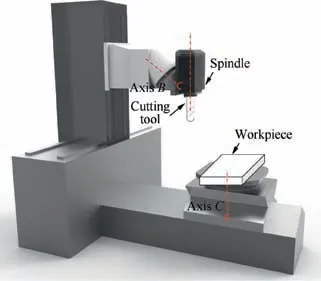
Fig. 1 Five-axis CNC machine tool structure with B-C rotations.
The relationship between the rotational axis drive torque and the angular acceleration can be represented as follows:

In Eq. (5), M is the drive torque, and JTis the rotational moment of rotation of the spindle. It can be found from Eq.(6)that,if the angular acceleration changes smoothly,the drive torque M will also change smoothly, i.e.,

The relationship between the angular acceleration jerk and the rotation angle can be represented as follows:

In Eq. (7), θ is the rotation angle of the rotary axis. If the rotation angle is third-order derivable,the rotation axis driving force M will change smoothly.
Therefore, if the contact angle of the cutting tool does not have sharp changes, the tool path curvature changes continuously and smoothly;if the rotation angle has a third-order continuousness,the cutting force stability of five-axis flank milling can be guaranteed, and a flexible impact to the machine tool can be avoided.
4. Tool path generation algorithm of five-axis flank milling of pockets
In order to ensure the smoothness of the cutting force during a machining process, the remaining material to be machined should be evenly removed. In this paper, the corner-looping milling strategy is used to realize an even change of the tool contact angle, and clothoidal spirals are used to realize a continuous curvature of the tool path.A combination of these two strategies is realized based on the iteration process considering the maximum cutting force and the range of the tool axis vector. Eventually, a five-axis flank milling tool path with a continuous curvature and smooth changes in the contact angle of the cutting tool is generated. The flow chart of the proposed algorithm is shown in Fig. 2.
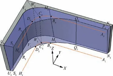
Fig. 3 Machining remains and tool path points in a corner.
4.1. Corner-looping tool path generation considering the maximum contact angle
The corner-looping milling strategy is applied so as to obtain an even cutting force in the corner area, and a cornerlooping tool path is generated by considering the maximum contact angle of the cutting tool. The contact angle refers to the center angle corresponding to the contact curve between the cutting tool and the workpiece during the flank milling process,which is the difference value between the cut entrance angle and the cut exit angle.The tool axis vector changes constantly,and the maximum contact angle in the tool axis direction also changes constantly.As shown in Fig.3,A0B0C0D0H0is a set of top path points,and A1B1C1D1H1is a set of bottom tool path points. Vectorsandare in the same direction, whileand, as well asand,are also in the same direction. According to the cutting force model, it can be found that at the intersection of the straight line and the arc exists the maximum contact angle of the micro-element. When point Biis machined, the contact angle Ψiis the largest, and so as the cutting force.
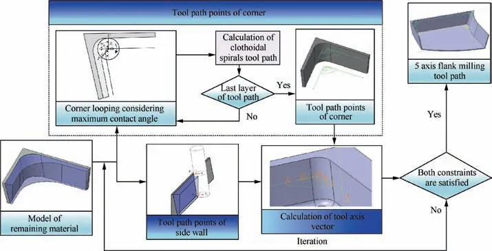
Fig. 2 Algorithm flow chart of pocket five-axis flank milling tool path generation.
According to the five-axis cutting force prediction model,the cutting force of point Biis calculated, and recorded as FB. If FB≤Fmax, where Fmaxcan be determined according to the corresponding cutting condition, the material to be machined at the corner can be removed by the tool path of this layer,and the tool path is the last layer;Ciis the intersection of the tool path and the angle bisector,and corner machining can be completed. If FB>Fmax, an additional looping tool path is required to remove the material until FB≤Fmax.
4.2. Clothoidal spirals tool path for curvature continuity
Considering the kinematics of machine tools, the curvature and the tool axis vector’s smooth changes can reduce machine vibration during a cutting process. In this paper, a five-axis flank milling tool path generation method is proposed to ensure that the curvature of a tool path is smoothly changed.The composition of a curve can be straight, clothoidal spirals,and arc, or arc, clothoidal spirals, and arc. Clothoidal spirals are used to connect arcs with different curvatures, which can avoid tool path curvature mutation.
The function representation of clothoidal spirals32can be as follows:

where l is the length of clothoidal spirals. P and Q can be represented as follows:

where ρ1and ρ2are the curvatures of the starting curve and the ending curve, respectively, and ρ1<ρ2. C is a constant value, and it can be represented as follows:

When the starting curvature is zero,the function of clothoidal spirals can be represented as follows:

Different shapes of clothoidal spirals can be obtained by adjusting parameter C.
According to the tool path curvature, the feed rate and the maximum acceleration of the machine amaxcan be obtained as

The acceleration jerk formula can be simplified by assuming that the tangent speed is kept unchanged,which means that the acceleration jerk in the tangent direction is 0,and jaafter simplification from Eq. (4) can be represented as follows:

Since the value of C is defined as the ratio of the line length change to the curvature change,Eq.(13)can be represented as follows:

When the cutting tool moves along with the curve, the acceleration increases in real time and takes the maximum when the curvature is zero. Considering the kinematics of machine tools, the acceleration jerk should be less than the given maximum, and then

A clothoidal spirals tool path is shown in Fig. 4, where EF is a clothoidal spiral, and FG is the arc. E is the starting point of clothoidal spirals. EF and the side tool path have the same tangent and the same curvature at point E.Point F is the intersection of clothoidal spirals and the arc. In order to meet the kinematics constraints of machine tools,arc FG and clothoidal spiral EF have the same tangent and curvature at point F.Since point F is both the ending point of clothoidal spirals and the starting point of the arc, it can satisfy the functions of both clothoidal spirals and the arc. Point F can be solved by the following formulas:
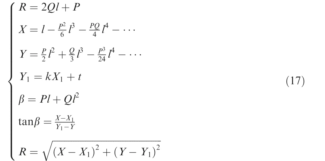
where R is the radius of curvature at point F, β represents the angle between the tangent and x-axis at point F, and (X1,Y1) is the coordinate of center O of circle FG. According to the above formulas, the coordinates of point F and center O of arc FG can be obtained. Similarly, clothoidal spiral GH can be obtained. If it is not the last layer of the tool path, an auxiliary tool path is calculated.The auxiliary tool path HIJE consists of clothoidal spiral HI,straight line IJ,and clothoidal spiral JE, which can be obtained according to the maximum acceleration jerk of the machine tool. Following the above steps,the next layer of the spiral curve tool path can be calculated until it is completed.According to the proposed method,top and bottom clothoidal spirals tool paths of one pocket can be calculated.
4.3. Tool axis vector adjustment for a corner by five-axis flank milling
Because the requirement of machining precision is high, the optimization range of the tool axis vector is limited in the process of flank milling. In order to ensure the quality of a machining process, the tool axis vector is calculated and adjusted according to the two-point offset method.
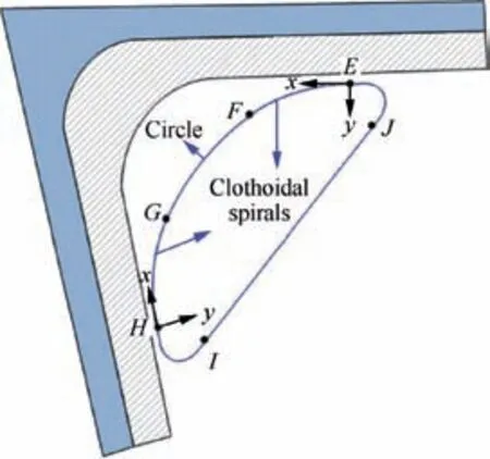
Fig. 4 The first layer of a clothoidal spirals tool path.
Top tool points Pt,iand bottom tool points Pb,iare obtained for the sidewall in Fig. 3, so the corresponding tool axis vector can be represented as follows:

After discretizing the tool path points at the corner,the top of the tool path points is represented as,and the bottom of the tool path points is represented as.The tool axis vectors corresponding to the tool path points at the corner can be represented as follows:

Not only the tangential direction of the tool path is continuously changing,but also the tool axis vector changes with the cutter location point in a corner milling process. The tool axis vector is determined by the rotation angle of the rotary axis.Through an analysis of the kinematics of the rotating axis, it can be found that the rotation speed of the rotating axis changes continuously,and the machine tool can run smoothly when the rotation angle has a third-order continuity,while the acceleration and acceleration jerk are satisfied to meet the requirements of the machine rotating axis.
In order to ensure a smooth change of the rotating axis,the tool path curve is discretized firstly, and the initial tool axis vector is calculated for each discrete point. Then,the relationship between the tool axis vector and the rotation angle can be established according to the kinematic model of the machine tool, and the initial rotation angle is calculated according to the known initial tool axis vector.In order to ensure a smooth running of the rotating axis,the uniform B-spline curve fitting method is used to smooth the rotation angle.In the absence of multiple nodes, the k-th B-spline basis function is continuous at node Ck-1at the support interval. If the number of nodes in the support interval is r, the basis function is continuous at node Ck-r. Since the B-spline function is a linear combination of the basis function for control vertices,the continuity of the B-spline curve is the same as that of the basis function. In order to ensure a third-order continuity of the rotation angle,the quartic B-spline curve is used to fit the rotation angle.

Since the change of the tool axis vector is very slight, the change of the cutting force will also be very slight. While the machining accuracy in some points cannot be satisfied, the rotation angle should be adjusted according to the machining accuracy requirement.
4.4.Tool path parameter iteration for a corner by five-axis flank milling
The machining error is the normal error of the tool envelope surface relative to the workpiece surface.33A lot of research has been done on the calculation method of the five-axis flank milling error.34The existing calculation method can be used to determine the tool envelope surface, and the machining error can be obtained quickly after the cutter location point and the tool axis vector are determined.
As shown in Fig. 5, the machining error of five-axis flank milling is mainly caused by two types of reasons,i.e.,the actual cutter location point deviation from the theoretical cutter location point and the parallelism deviation between the tool axis and the surface generatrix.For the first type of error,it can be eliminated by adjusting parameter C of the clothoidal spiral.If parameter C approaches infinitely small, the change value of curvature approaches infinity, the clothoidal spiral tool path infinitely approximates to the theoretical state of the workpiece,and then the cutter location point error approaches zero.For the second type of error,the number of discrete points can be increased so as to make the tool axis variation smoother,and the local tool axis vector can be adjusted by an appropriate value to ensure machining accuracy.
Based on the above analysis, when the calculated machining error exceeds the permitted error range,adjustment should be made on tool path points and tool axis vectors.The parameters of the other associated tool points and tool axis vectors can also be adjusted correspondingly with the process of machining error recalculation. Through the iterative process,a feasible tool path for five-axis flank milling of pockets is generated.
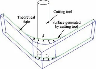
Fig. 5 Machining error of five-axis flank milling in a corner.
5. Prototype system implementation and case studies
5.1.Some cases of tool path generation for five-axis flank milling of pockets
Some cases of tool path generation of five-axis flank milling for pockets are studied to validate the proposed algorithm. Fig. 6 shows different pockets using the tool path generation method proposed in this paper.
The curvature of the tool path curve at the corner is analyzed by the curvature analysis module of CATIATM. Fig. 7 shows the corner tool path of the third pocket in Fig. 6. In Fig. 7(a), from the straight line tool path to the corner tool path,the curvature of the tool path generated by the proposed method changes evenly from 0 to a certain value, while for a corner-looping tool path without using clothoidal spirals, the tool path curvature changes suddenly from 0 to the maximum value.According to the analysis of Eq.(6),a sudden change of the tool path curvature will lead to a sudden change of the acceleration jerk, which may lead to unstableness for the machine tool.
5.2. Case study with experimental results and discussion
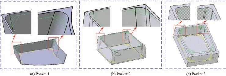
Fig. 6 Five-axis flank milling tool paths for different pockets.
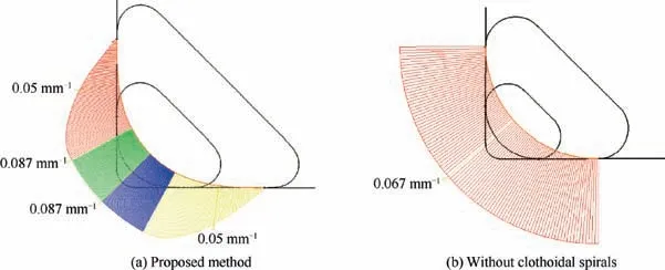
Fig. 7 Tool path curvature analysis.
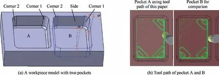
Fig. 8 Workpiece model and simulation of tool paths.
In order to verify the application effect of the proposed tool path generation method in a real machining process, the third pocket flank milling tool path generated in Section 5.1 is tested and verified. The tool path is generated by inputting the machine model, the workpiece model, and the cutting force coefficient library.
As shown in Fig. 8(a), two identical pockets A and B are processed in the experiments respectively by using two different machining strategies, and the pitch angle of the sidewall surface is 11.3° (α in Fig. 8). The two pockets are machined with the same machine tool, same material, same type of cutting tools, and same cutting parameters, but by two different mill strategies.Pocket A is processed by the strategy proposed in this paper, while pocket B is machined by the strategy of corner-looping milling whose corner is circular rather than clothoidal spirals,and this strategy has been widely researched and developed by academic and industrial areas. The material used in the experiments is Titanium alloy TC4 with a blank size of 80 mm×60 mm×25 mm, the cutting tool diameter is 12 mm, the spindle speed is 850 r/min, the feedrate is 300 mm/min, the cutting depth is 2.5 mm,the nominal cutting width is 3 mm,and the cutting parameters are set according to industrial applications.The experimental tool path is shown in Fig.8(b).The experimental equipment is a DMG 80P five-axis machining center with B-C axis rotations.

Fig. 9 Experimental setup.
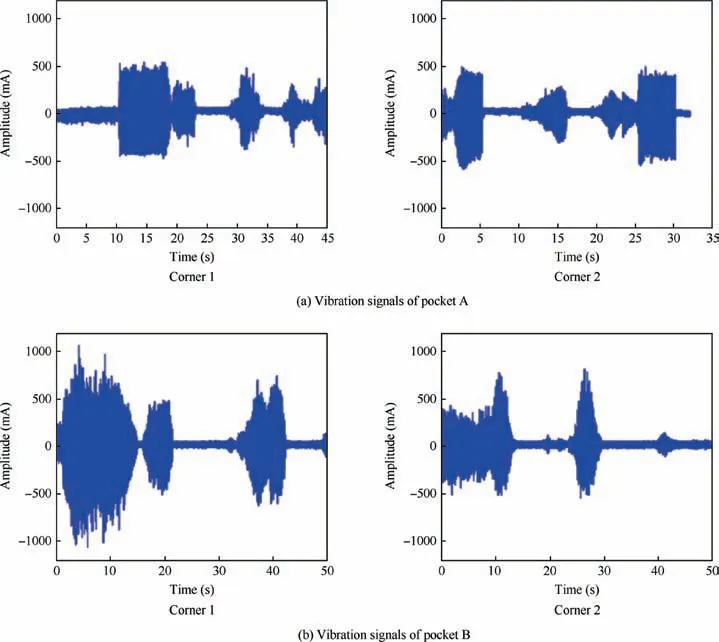
Fig. 10 Vibration signals during the machining process.
Cutting force and vibration signals during the process are monitored by a Kistler 9257B piezo dynamometer and a BVM-PC-50 vibration sensor, respectively. A roughness measuring instrument is used to measure the workpiece surface quality after the machining process. Machining setup and the finished workpiece after the machining process are shown in Fig. 9.
Vibration signals during the machining process of pockets A and B are shown in Fig. 10. Compared with that of the corner-looping milling strategy without clothoidal spirals, the maximum value of vibration is reduced by 38%, the average value of vibration is reduced by 9%,and the surface roughness of the workpiece is improved from 3.68 to 2.36 μm with the strategy proposed in this paper. The tool path curvature changes evenly, the feedrate meets the kinematics of machine tools, and the peak of vibration of the process is less, so the surface roughness is improved.
Cutting force signals of two corners during the machining process of pockets A and B are shown in Fig. 11. Both of the maximum values of the cutting forces of pockets A and B are about 1300 N.It can be found that the maximum cutting forces are not very different, because the corner looping strategy is applied to both of the tool paths. However, it can be found that the cutting force change of pocket A is much smoother than that of pocket B due to optimization of the tool path curvature. Firstly, the sharp peak values of pocket A are much less than those of pocket B; secondly, the lasting of a stable cutting force of pocket A is much longer than that of pocket B; thirdly, the peak value transitions of pocket A are much smoother than those of pocket B.
6. Conclusions and future work
In this paper, multiple relationships among tool path points,tool axis vectors with cutting forces, and kinematics of machine tools are established. The strategies of cornerlooping milling and clothoidal spirals are combined so as to find feasible solutions under the two constraints of the cutting force and the kinematics of machine tools.Parameters are iterated by considering the maximum cutting force and the range of the tool axis vector, and eventually a curvature continuity five-axis flank milling tool path with a smooth cutting force is generated.Machining experimental results show that the maximum cutting force is kept within a safe cutting force threshold, the change of the cutting force is much more even, the maximum value of vibration is reduced by 38%, the average value of vibration is reduced by 9%,and the machining quality of the surface is improved from Ra3.68 to Ra2.36 μm.
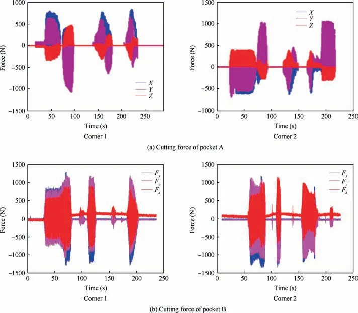
Fig. 11 Cutting forces during the machining process.
Our future work will focus on optimizing the iteration algorithm for determining tool path points and the corresponding axis vectors. In addition to that, the influence of the feedrate on the cutting force will also be taken into account by the model.
Acknowledgements
The research work presented in this paper was primarily supported by the National Natural Science Foundation of China- China Aerospace Science and Technology Corporation on Advance Manufacturing (No. U1537209), National Natural Science Foundation of China (No. 51775278), and Jiangsu Province Outstanding Youth Fund of China (No.BK20140036).
 CHINESE JOURNAL OF AERONAUTICS2020年2期
- CHINESE JOURNAL OF AERONAUTICS的其它文章
- Delaying stall of morphing wing by periodic trailing-edge deflection
- Optimization and verification of free flight separation similarity law in high-speed wind tunnel
- Non-intrusive reduced-order model for predicting transonic flow with varying geometries
- Consideration on aircraft tire spray when running on wet runways
- Aeroelastic simulation of the first 1.5-stage aeroengine fan at rotating stall
- Experimental study on NOx emission correlation of fuel staged combustion in a LPP combustor at high pressure based on NO-chemiluminescence
