Finite element modelling and experimental investigation of the impact of filling diあerent materials in copper tubes during 3D free bending process
Xunzhong GUO, Xuan CHENG, Yong XU, Ji TAO,Ali ABD EL-ATY, Hai LIU
a College of Material Science and Technology, Nanjing University of Aeronautics and Astronautics, Nanjing 211100, China
b Jiangsu Key Laboratory of Nuclear Energy Equipment Materials Engineering, Nanjing University of Aeronautics and Astronautics, Nanjing 211100, China
c Institute of Metal Research, Chinese Academy of Sciences, Shenyang 110016, China
d School of Materials Science and Engineering, Nanjing University of Science and Technology, Nanjing 210094, China
e Department of Precision Manufacturing Engineering, Suzhou Vocational Institute of Industrial Technology, Suzhou 215104, China
KEYWORDS 3D free bending;Ellipticity;Filling bending;Finite element modelling;Force model;Thickness
Abstract 3D free bending process, an advanced metal forming technology, has attracted much attention due to its unique geometrical flexibility and efficiency. Filling tubes with materials may effectively reduce the distortion in the cross-section area and restrain wrinkling and collapse of tube wall. In the present study, the impacts of filling different materials on the copper tubes during 3D free bending process were investigated. We have found that copper tubes filled with low melting point alloys could induce the most uniform stress distribution, which result in better formability and moderate thickness changing rates when compared to SS304 steel balls and PU rubbers. The lowest ellipticity reached to 1.467%.
1. Introduction
Recently, tube bending technology has become one of the key manufacturing technologies for lightweight product forming because tubular geometries are employed in many high-end industries,1such as automobile,aerospace and aviation,where lightweight and high-strength product from both materials and structural aspects are increasingly used.2,3As a new technology,3D free bending technology has the great potential4to be suitable for the most tubes and profiles because of its geometrical flexibility and efficiency.Hence,it can be used to produce complex hollow tubes with asymmetric cross-sections and continuous varying radii.5Also,the bending of different R values and angles can be achieved without changing the die,which greatly extends the flexibility of the bending machine. On the other hand,during the tube bending process,wall thickness and cross section changes are unavoidable.6However, due to the axial force, wall thickness and cross section changes are restrained during 3D free bending technology.
Murata, et al.7proposed free bending technology for the first time to precisely bend complex hollow tubes and profiles with different radius without die change or re-clamping. They presented calculations regarding the bending moment (M).Beulich, et al.8developed a finite element simulation model for the free-bending process with 6 degrees of freedom and critical parameters for the result of the bending process are therefore evaluated and optimized. Based on the research results, Guo, et al.9proved the reliability of U-R relationship which is obtained from FE modelling. Gantner, et al.10developed finite element analysis (FEA) models to simulate the above bending technology and the results were verified by bending experimental tests. Furthermore, a theoretical model based on both kinematic and mathematical simulation was introduced to determine the bend die’s control data.11Zhou,et al.12utilized 3D free bending technology to analyze features like bending trend, springback, side bending, and twisting of L-shaped aluminum under different bending conditions using simulations and experiments.
3D free bending is a dieless forming technology, making it hard to keep stable and restricted springback during the bending process.13However, several materials could be used inside the tubes for supporting roles. These materials are not only used for restraining thickness changes and springback of the tubes,14but also to further improve formability. Over the last few years, many experimental and numerical methods have been used to investigate the effects of filling materials on forming limit and formability during tube bending process.15Combined with experiment and simulation, numerical study on bending behavior under different clearance between tube and various dies and different bending radii is conducted in terms of wrinkling,wall thinning and cross section deformation.16-18Yang and Lin19proposed a wrinkling wave function and established a simplified wrinkling prediction model to predict the minimum bending radius.Sedighi and Kahnamouei20filled the tubes with low-temperature melting metals and different types of rubbers to compare the restricting defects, such as wrinkling and cross-section distortion during bending of thin-walled tubes. Mandrel is widely used as filling material.For instance, Al-Qureshi21presented a novel technique for bending thin-walled tubes using flexible mandrel of elastomeric rod. They found that elastomer is also suitable for use in the tube bending in other traditional bending technologies.Rezaei,et al.22studied the effects of polyurethane foam-filler on the axial splitting process of circular composite tubes under the axial quasi-static loading, and found that foam-filled circular tubes under the axial compression in the splitting process worked as good energy dissipater. Shen, et al.23found that the position and the size of the mandrel greatly influenced ovalization of the cross-section. Zhang, et al.24studied the effects of three different mandrels on the cross-sectional deformation by introducing disconnect-type rigid mandrel and two PVC elastic mandrels with different shapes. Since finite element simulation is an effective tool to study the bending process,Li,et al.25established an analytical mandrel model to select the mandrel parameters.Thereafter,they investigated the influence of mandrel on the stress distribution during the bending process. Liu, et al.26established models filled with rigid and PVC mandrels for E-typed and H-typed rotary draw bending of H96 brass double-ridged rectangular tubes. They concluded that PVC mandrel had better effects.
From the aforementioned literature, it is crucial to fill the materials like solid filling and flexible filling during 3D free bending process to determine their effects.However,the study on filling materials in reported studies is so far not systematic.In particular, no comparison of formability and influence under different filling materials are so far presented. Most of recent studies mainly focused on the influence of the solid filling (e.g., mandrel, steel balls, low melting point alloy) on formability. However, the influence of flexible fillings (e.g.,PU rubber) on formability of materials is still rarely investigated. Furthermore, no related mechanical models are established to further study the mechanisms affecting formability.
In this study,different filling materials were used in copper tubes during 3D free bending process in order to investigate the influences of filling materials on formability. To this end,simulation and experiments were conducted to analyze the process. A mechanical model was established to study the mechanism of the different filling materials on the final induced formability. Using the mechanical model, the effects of solid filling and flexible filling were investigated. Finally,finite element simulations combined with experiments were employed to verify the theory.
2. Theoretical analysis
As depicted in Fig. 1, during 3D free bending process, the internal side of the tube was subjected to compressive stress while the outside was influenced by tensile stress. This led to thickening of the internal side of the tube and reduction of its outside. Meanwhile, the tube was subjected to feeding force,27so the neutral layer offset outwards to restrain reduction of the wall thickness and reduce the deformation of the cross section of the bent tube.
In Fig.1,ρaand ρbare bending radius of inside and outside wall of tube,respectively,t is the thickness of tube at any point and t0is the initial thickness of tube, N is the interaction between filling materials and tube, and P is the feeding force.
In order to improve the accuracy of the theoretical model,some assumptions are necessary to be made and the relative derivation processes are shown as following: The principal stress space in the deformation area is assumed to Cartesian coordinates system of axial θ, radial ρ and circumferential φ axes, and it meets the Hencky’s stress-strain relationships:

Due to the existence of the feeding force, the deformation of the cross-section is restrained,and the circumferential strain(εφ) in plane is about equal to 0:

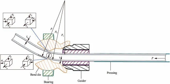
Fig. 1 Tube bending stress and strain analysis.
The tube is defined as incompressible material,and it corresponds with the law of volume invariance:

Based on Eqs.(2)and(3),the equivalent strain can be given as:

where superscript + refers to absolute value of ερ.
The radial strain ερcan be approximately determined by the dimensions of tube thickness:

Considering Eq. (5), Eq. (4) can be rewritten as:


According to the Von-Mises yield condition:
where kfrefers to flow stress.
By combination of Eqs. (1)-(3) and Eq. (7), the following relations can be obtained:

where sgn (·) denotes as a sign function.
The equilibrium equations can be expressed as Eqs. (9-1)and (9-2) in the radial direction:

Considering Eq. (8), Eq. (9-2) can be rewritten as:

Then the boundary conditions at the outside and inside surfaces of tube are:

Considering boundary conditions of Eq. (11), Eq. (10) can be expressed as:

The following relations can be obtained using Eqs. (6) and(12)

where Y denotes relationship between flow stress and the equivalent strain.
Many laws have been developed to describe the relationship between flowing stress and equivalent strain.All these laws are based on Drucker postulate which is also usually referred as first order convexity condition. From the Eq. (13), it can be concluded that N is a function of Δt,and the uniform distribution of N leads to uniform distribution of Δt in the circumferential direction.From the Eqs.(5)and(6),it can be found that Δt has a great influence on ερ.When Δt distribution is uniform,ερalso distributes evenly,then the deformation in radial direction is uniform. The above analysis proves that N has a great effect on ερ, so the more uniform distribution of N is, the greater formability and moderate thickness changing rates can be obtained in radial direction.In this paper,the stress distribution is obtained under different filling conditions to choose the most suitable filling materials.
3. Numerical simulation
3.1. FE model for tube simulation
To investigate the three-dimensional free bending process of tubes filled with different materials, ABAQUS/explicit was used to numerically simulate the forming process. The FE model of this process is shown in Fig.2 which includes a tube,a bend die,a spherical bearing,a guider,a pressing,and different filling materials. Each die model created during the geometry modelling was oriented in its own coordinate system and was independent of the other geometry models, and then the dies and tube were assembled in the global coordinate system.These data were put in CATIA software and then imported to ABAQUS/explicit FE code (Fig. 2).
The tube was made of copper and filling materials were steel balls, PU rubber and low melting point alloys, respectively. PU rubber and low melting point alloys were defined as deformable bodies and meshed by C3D10M solid element.The copper tubes were meshed using C3D8R solid elements which were eight-node linear brick with reduced integration elements while other parts and steel balls were defined as rigid bodies with R3D4 elements type. The interaction was set to general contact,and the analysis step was adjusted to dynamic explicit. Since the lubrication unit was designed near the bend die, the coefficient of friction between the dies and the tube were assumed very low.Thus,based on a great deal of simulation results,the coefficient of friction between the dies and the copper tubes were identified as 0.02. Meanwhile, the pressing and guider were set to encase. The tube was set a specified movement speed in the Z direction and the bearing was set two movements respectively in the X and Y direction while the remaining degrees of freedom were all fixed.
3.2.Material properties of copper tube different filling materials
As noted,the tube material used was copper TP1 tube.In this study,the uniaxial tensile tests with the extensometer were carried out to obtain the true stress-strain curve of copper tube,as shown in Fig. 3.
The bend die was set to YG8 cemented carbide and the specific parameters of the both the components are listed in Table 1.As shown in Table 1,the yield strength of copper tube and bend die were 294 and 2451 MPa, and the Poisson’s ratio was 0.32 and 0.3,respectively.The mechanical properties were applied to the numerical simulations and the experiment.
The relevant parameters of filling materials, such as steel balls, PU rubber and low melting point alloy are listed in Table 2.As described in Section 3.1,the steel balls were defined as rigid balls, so the mechanical properties of steel balls were neglected.
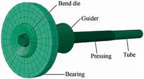
Fig. 2 FE modeling of tube free bending.
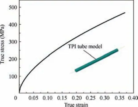
Fig. 3 True stress-strain curve of copper tube.
According to ASTM E9-89a(2000)Standard Test Methods of Compression, the samples of low melting point alloys for compression test were cast into cylinders with dimensions of∅18 mm×18 mm. The compression tests of low melting point alloys were conducted using a universal testing machine and a force-displacement curve was obtained.Moreover,Elastic modulus and Poisson’s ratio of the low melting point alloys were obtained from tensile test, and the samples of the tensile test were manufactured according to the international standard ASTM E111-04. The true stress-strain curve was obtained using an extensometer to measure the stress and strains, as shown in Fig. 4.
PU rubber behaves in a nonlinear elastic manner; thus in the FE simulation, the Blatz-Ko model was selected as the most appropriate material model for PU rubber.The mechanical properties of PU rubber were obtained by uniaxial tests,biaxial tests and planar tests, as shown in Table 2.
3.3. Influences of different filling materials during 3D free bending process
3.3.1. Simulation conditions
In order to simulate the free bending process filled with different materials, simulations for four copper tubes were carried out based on the conditions summarized in Table 3.
The bending angle (φ) was set to be 120°, and the bending radius was 78 mm.The outer diameter of the tube was 15 mm and its thickness was 1 mm. The length of the tube was 500 mm and the distance A between center of the bend die and front end of the guide was 30 mm. The eccentricity U between central axis of the guide and center axis of the bend die in Y direction was set to 4.5 mm. The filled materials included steel balls, PU rubbers,and low melting point alloys.The relative position sizes were shown in Fig. 5.
3.3.2. Bending without filling materials
In order to investigate the influences of different filling materials in 3D free bending,bending was first simulated without filling materials.The simulation results are shown in Fig.6.It can be seen that stress distribution was not uniform,and maximum stress was only 268.1 MPa, which attributed to the lack of the supporting force inside the tube.Hence,it was necessary to fill the tubes with materials.

Table 1 Relevant parameters of different materials.

Table 2 Relevant parameters of filling materials.
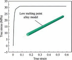
Fig. 4 True stress-strain curve of low melting point alloys.
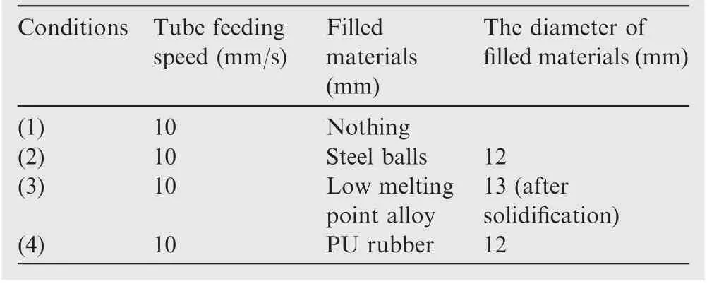
Table 3 Main parameters used for simulation of different conditions.
3.3.3. Bending with different filling materials
The simulation results under condition (2) are gathered in Fig.7.The stress distribution of the copper tubes after bending with filled SS304 steel balls increased.Also,the stress distribution appeared more inhomogeneous, because SS304 steel balls were movable during bending and the contact between SS304 steel balls and tube wall was the point contact, a kind of discontinuous contact way.
The simulation data of bending using fillers with low melting point alloys are depicted in Fig. 8. The low melting point alloy established a complete contact with tube wall after solidification,and the stress distribution was uniform during bending process. Fig. 8 revealed ideal forming results.
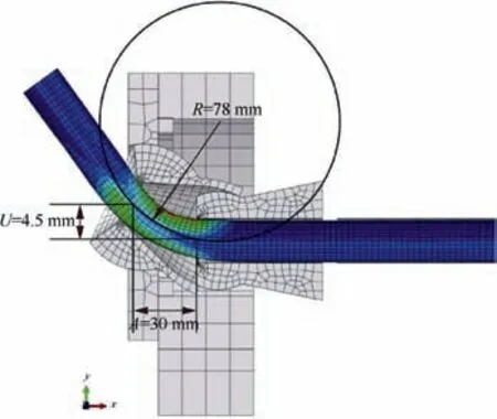
Fig. 5 Model assembly position.
The simulation results under condition (4) are shown in Fig. 9. Due to the lowest elastic modulus, PU rubber was unable to provide internal pressure.Hence,the stress was only 258.9 MPa, and both maximum and minimum thicknesses were 1.159 mm and 0.9479 mm, respectively. Compared with condition (1) (Fig. 6), during the forming process, the tube bears less stress and the stress distribution is more uniform when the filling materials were replaced with PU rubber.
4. Results and discussion
4.1. Free bending experiments
3D free bending experiments were carried out on the independently developed three-axis free-bending system under optimized process parameters obtained from simulations. To prevent the leakage of steel balls and PU rubber, the ends of copper tube were sealed by low melting point alloys. The machine is basically composed of three servo motors.In forming process,two servo motors drive the bend die shifting in the X and Y directions,and the rotation around the center is done by the spherical connection of the bend die to the guider. The other servo motor which works in the Z direction to feed the tube into the bend die is thereby synchronized with the X and Y axes of the bend die. Lubricating oil was continuously filled to the forming part to reduce the friction resistance during the forming process. The experimental process and results under different conditions are shown in Fig. 10.
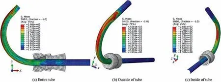
Fig. 6 Result of bending simulation under condition (1).

Fig. 7 Result of bending simulation under condition (2).
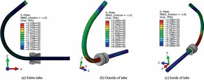
Fig. 8 Result of bending simulation under condition (3).
4.2. Effect of filling materials on wall thickness variation
The reliability between experimental the results and simulation results for free bending is shown in Fig.11,it can be seen that the wall thickness obtained by FE modelling and experimental is in accordance with each other. The maximum relative error between the experimental and simulation results is less than 18.4%, indicating the reliability of FE model used in this study. The imprecise measurement of friction coefficient plays a vital role in free bending process which cause the error between experimental and simulation results. As shown in Fig. 11, the trends of inner thickness distribution of copper tubes were similar while filled with different materials. Using low melting point alloys under condition (3) as typical solid filling materials, the inner thickness change was minimal and maximum changing rate was only 13.5% at bending angle of 90°. Correspondingly, using PU rubbers as filling materials in condition (4) as representative flexible filling, the inner thickness changing rate reached up to 15%. Compared with condition (1), when steel balls were used as filling materials,the inner thickness changing rate has increased, and the inner surface quality was worse, while the indentations in the inner arc are deeper than those in the outer arc.
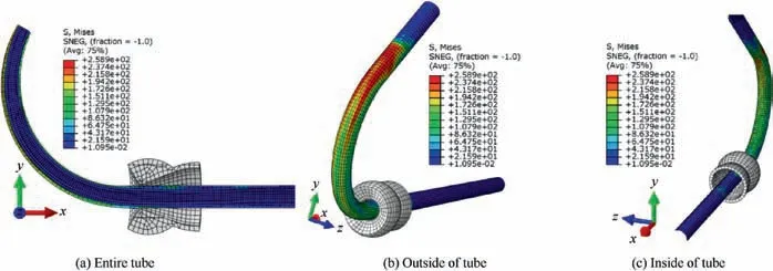
Fig. 9 Results of bending simulation under condition (4).
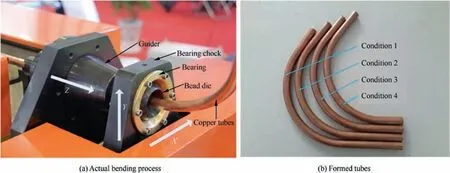
Fig. 10 Experiments of three dimensional free bending under different conditions.
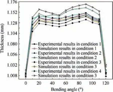
Fig. 11 Inner thickness distribution under different conditions.
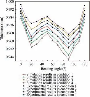
Fig. 12 Outer thickness distribution under different conditions.
Fig.12 shows the outer thickness distribution of the copper tubes under different conditions,the trends of the experimental results are consistent with simulation results,which proves the reliability of the theoretical model again. It can be observed that the outer thickness distributions were similar, and the changing rate was minimal for copper tube filled with low melting point alloys. Under condition (4), when copper tubes were filled with PU rubbers, the outer thickness reduced to 0.954 mm as well as the outer thickness maximum changing rate was reached to 4.6% at bending angle of 90°. However,compared to condition (1), instead of decrease in outer thickness changing rate, tubes filled with steel balls showed increased outer thickness changing rates.

Fig. 13 Cross section deformation under different conditions.

Table 4 Maximum and minimum diameter and ellipticity under different conditions.
When the servo motor drives the bend die shifting in the positive direction of Y axis, N enlarges the total radial stress.Thus, the materials on the outside of the tube flow along the tangent direction. This is why the wall thickness is thinning on the outside of tube.Similarity,when the servo motor drives the bend die shifting in the negative direction of Y axis, N has the same effects on wall thickness thickening.Therefore,different N has different effect on wall thickness variation.
4.3. Effect of filling materials on cross-section distortion
As shown in Fig.13,the filling materials greatly influenced the ovalization of the cross-section. The following equation was used to investigate the specific functions of different filling materials.

where η is the ellipticity of the tube cross-section,dmaxand dminare respectively the maximum and the minimum diameter,and d0is the initial diameter.
Table 4 presents the maximum and minimum diameter of the tubes and the ellipticity under the different conditions. It can be observed that the simulation results are larger than the experiment results with same variation trend, the maximum diameter (16.45, 15.43 mm respectively) and the minimum diameter (14.25, 14.67 mm respectively) are occurred synchronously in simulation and the experiment when filled with nothing, meanwhile, the ellipticity is decreased regardless of the filling materials. In particular, the lowest ellipticity reached to 1.467% for filling materials with low melting point alloys (condition (3)).
4.4. Variation of mean stress distribution
Fig. 14 shows the numerical simulation results of mean stress distribution of copper tubes under different conditions,respectively.As depicted in this figure,the mean stress located in the initial and the terminal of the tube is almost larger than other positions, the first peak appeared at 20° cross-section and the second peak occurred at 90° cross-section. Meanwhile, the mean stress distributed in the middle part of bending tube is relatively homogeneous.It indicates a transition into the stable deformation stage.As shown in Figs.11 and 12,it is noteworthy that the peak values of wall thickness thinning and thickening both appear at the same position of the tube. From Fig. 14, it can be found that the mean stress distribution is more uniform when copper tube filled with low melting point alloys,at the same time,the inner and outer thickness distribution is much more uniform than other filling materials. Combined with the mean stress and thickness distribution, it can approve that the greater formability and moderate thickness changing rates can be obtained when mean stress distribution is more uniform, which is consistent with theoretical analysis.
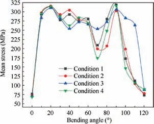
Fig. 14 Mean stress distribution under different conditions.
On the other hand,steel balls were able to move or deform in the tubes, hence couldn’t provide continuous supporting forces affecting ovalization of cross-section and wall thickness uniformity.
Due to the good elasticity of PU rubber, the PU rubber mandrel could not provide sufficient internal pressure during bending process, therefore, the formability has not been improved. An additional problem was that it was difficult to remove mandrel from the tube after forming.
5. Conclusions
(1) The interaction N between filling materials and tube has a significant effect on formability.The more the uniform distribution of N is,the better the formability and moderate change in thickness attained along the radial direction.
(2) Compared to the flexible filling, copper tubes filled with solid filling (such as low melting point alloys and steel balls) could contribute to better formability and less change in thickness.
(3) On the other hand,filling tube with steel balls led to bad formability and great change in thickness than unfilled tubes. Meanwhile, large numbers of spherical indentation is developed on the inner surface results in degradation of the inner surface quality.
(4) The ellipticity decreased regardless of the filling material and filling with low melting point alloys reduced ellipticity to 1.467%.
Acknowledgements
The authors gratefully acknowledge the financial support from the Open Research Funds of the Jiangsu Key Laboratory of Nuclear Energy Equipment Materials Engineering of China(No. NJ20170012), the China Aviation Science Foundation(No. 2016ZE52047) and the Jiangsu Province Science and Technology Program of China (No. BE2016156).
 CHINESE JOURNAL OF AERONAUTICS2020年2期
- CHINESE JOURNAL OF AERONAUTICS的其它文章
- Delaying stall of morphing wing by periodic trailing-edge deflection
- Optimization and verification of free flight separation similarity law in high-speed wind tunnel
- Non-intrusive reduced-order model for predicting transonic flow with varying geometries
- Consideration on aircraft tire spray when running on wet runways
- Aeroelastic simulation of the first 1.5-stage aeroengine fan at rotating stall
- Experimental study on NOx emission correlation of fuel staged combustion in a LPP combustor at high pressure based on NO-chemiluminescence
