An innovative approach for integrated airline network and aircraft family optimization
Jose´ ALEXANDRE, T.G. FREGNANI, Bento S. DE MATTOS,Jose´ A. HERNANDES
Department of Aeronautical Engineering, Technological Institute of Aeronautics, 12228-900 Sao Jose dos Campos, Brazil
KEYWORDS Air transport;Aircraft design;Airline economics;Airline network optimization;Multidisciplinary design optimization
Abstract The determination of optimal aerial transport networks and their associated flight frequencies is crucial for the strategic planning of airlines,as well as for carrying out market research,to establish target markets,and for aircraft and crew rostering.In addition,optimum airplane types for the selected networks are crucial to improve revenue and to provide reduced operating costs.The present study proposes an innovative approach to determine the optimal aerial transport network simultaneously with the determination of the optimum fleet for that network, composed of three types of airplanes (network and vehicle integrated design). The network profit is maximized.The passenger’s demands between the airports are determined via a gravitational model.An embedded linear programming solution is responsible for obtaining potential optimal network configurations. The optimum fleet combination is determined from a database of candidate aircraft designs via genetic algorithm. A truly realistic airplane representation is made possible thanks to accurate surrogate models for engine and aerodynamics is adopted.An accurate engine deck encompassing a compression map and an innovative engine weight calculation besides an aerodynamical artificial neural network module enable a high degree of accuracy for the mission analysis. The proposed methodology is applied to obtain the optimum network comprised of twenty main Brazilian airports and corresponding fleet.
1. Introduction
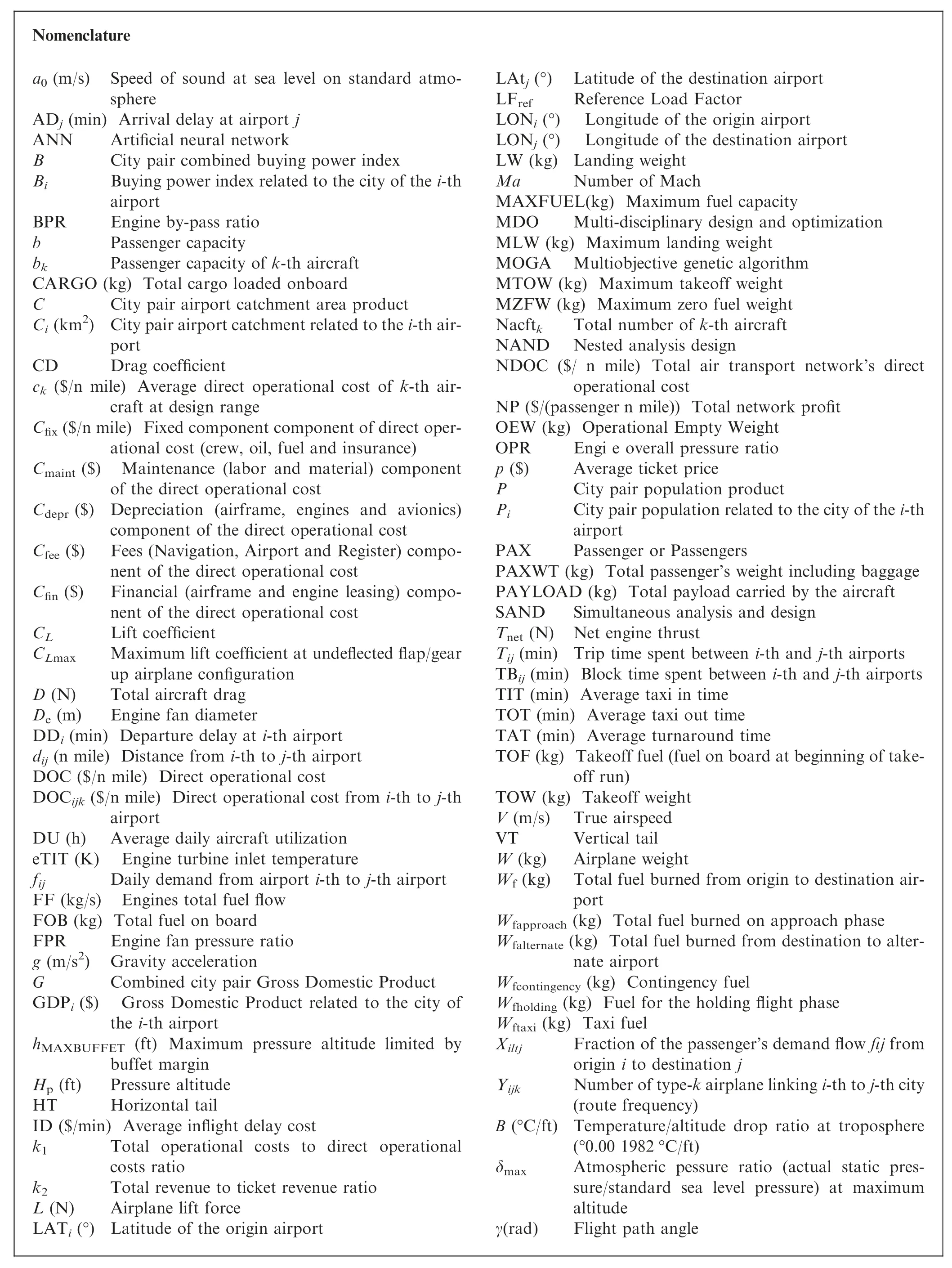

The need for reduction of operational cost is widely agreed by the commercial air transportation industry. Indeed, the segment is characterized by low operational margins. As per recent studies,1since the 1980’s the average world airlines profit margin has demonstrated a narrow variation, from-4% to 3%. Optimization methods have been widely applied to reduce operational costs, such as fuel-efficient flight paths,optimum slot allocation and turnaround time reduction.2They can already be applied in the airline’s operational planning process, which is divided into three major blocks, as shown in Fig. 13. The first block is called Schedule Generation (or Flight Definition). There, route allocation is determined according to the estimated or actual demand among city pairs,taking into consideration airport constraints, such as operational hours or infrastructure issues. Afterwards, the amount of frequencies for each city pair is determined based on the capacity of the selected aircraft type followed by the generation of the airline’s flight schedule. In this block, the objective function is normally set to market revenue maximization.4,5The second block is related to fleet assignment and there the sequence of scheduled flights of each type of aircraft is determined. In this process, the best aircraft is assigned to each scheduled flight with the objective to maximize profit at selected routes, considering maintenance and aircraft performance constraints.In Block 2,the objective function is usually established to maximize profit.6After network and type of airplanes are determined, the last block is related to crew assignment, where crew members are allocated to each flight,complying with labor regulations and technical constraints,on a rostering/pairing scheme.In this block,the objective function is normally set to cost minimization.4,7
The independence of the blocks shown in Fig. 1 is worth mentioning, where costs and revenues are related to each step in the airline planning cycle.7Because of this,some models are built to solve the problem in a single step,where the minimization of costs or maximization of revenues are set as objective function.3However, the unified model to optimize the entire process leads to large-scale problems, sometimes involving non-linear programming algorithms8and therefore significant computational power may be required for the complete solution. The selection of the aircraft fleet types suited to the network is most of the times performed prior to the optimization of Block 1, which is a significant factor that influences the flight frequencies. The determination of the optimal flight network and associated frequencies is a key step for airlines to elaborate their strategic planning, from market determination to aircraft and crew rostering. An optimal solution for this block facilitates the solution for the others. Furthermore, if in this optimization,the optimum aircraft types could be associated with the assigned network, the goal for maximum revenue and/or minimum operational costs would be even further improved. In other words, the network optimization is normally carried out separately from the aircraft optimization in the airline planning process.
Some aspects related to the conceptual design of commercial transport airplanes shall be mentioned at this point. Typically, this design phase is carried out by aircraft manufacturers(and frequently be the academia) through optimization of averaged direct operational cost in each set of stage lengths(or ranges),carefully chosen by the project team.Considerations about the suitability of the product into a realistic airline network are usually not given. In order to capture more realistic design scenarios,a common approach is to conduct surveys with airlines to incorporate their requirements into the project. Airline representatives are usually allocated into an aircraft development program council in order to provide regular feedbacks on design reviews. However different airlines present different requirements for their fleets, highly influenced by their business model and operational profile,sometimes not explicit to this kind of committee for strategic reasons. Because of this, families of aircraft types (derived from a single model)are offered to customers,in order to provide a range of solutions for different airline profiles and business models.
Until the 1990’s, the tools used for the aircraft conceptual design were limited by computational power.Simplistic models were developed in several aeronautical disciplines, and therefore this led to lower fidelity of the disciplines.Because of that,aircraft designers most of the times restricted mission requirements and performed optimizations focused on subsystems,ignoring the high degree of dependency that exists between airplane and network, resulting in a sub-optimization of system functionalities.
With the increase of the computational power, the aircraft conceptual design process is nowadays carried out by manufacturers using Multidisciplinary Design Optimization(MDO) frameworks. A great deal of computational analysis is required to obtain optimum configurations to satisfy many objectives and design constraints. Disciplines such as aerodynamics, propulsion, flight mechanics, structures and aeroelasticity, among others, are frequently considered in the optimization framework to obtain more realistic geometries of flight vehicles in addition to mission analysis into the network. Because of the increased complexity of such kind of methodology, significant efforts of computational analysis are required to obtain optimum configurations that satisfy many objectives and design constraints. Disciplines such as aerodynamics, propulsion, flight mechanics, structures and aeroelasticity, among others, are frequently considered in the optimization framework to obtain more realistic geometries of flight vehicles and, recently, the addition of flight profile and mission analysis. Nowadays, many design variables (and types) may be employed, and advanced optimization algorithms enable that complex models of the aeronautical disciplines be considered. Empirical formulae like the Class-I and-II methodologies proposed by Torenbeek9and Loftin10for drag and weight estimation are still extensively used for modeling because they provide faster results.11However,surrogate techniques have been increasingly adopted to model the physics with enough precision,at the same time reducing the computational time of complex and heavy calculations in MDO frameworks.12

Fig. 1 Typical operational planning process of airlines.3
Genetic Algorithms (GA) have been successfully employed and they are suitable for complex multi-disciplinary problems involving different types of design variables and efficiency on converging to the global minima,although not mathematically proven.13Besides, GAs can handle complex design frameworks, since they do not require function derivatives and can deal with different types of design variables and constraints.14
In order to produce realistic results, the airplane representation used in design framework is considerably more complex and sophisticated than that utilized by many authors. For instance, the airplane is modeled with CAD surfaces inside the optimization platform, which allows to easily calculate areas, angles and dimensions. In comparison, Taylor and De Week15or Bower and Kroo16ran optimizations with only a single objective cost function and adopted just three aircraft design parameters (range, lift-to-drag ratio, and cruise speed),associated to simplistic frameworks with few disciplines. The present work considers over 60 parameters to generate an airplane. Furthermore, the inclusion of the network in airplane design frameworks with realistic performance calculations is highly desirable.
Some of the design variables and constraints considered in the airplane generation are:
(1) Geometric variables: front fuselage, tailcone, fuselage cross-section shape and dimensions, wing planform characteristics and wing airfoil geometries, wing structural sizing, vertical and horizontal tail characteristics,winglets, and landing gear sizing.
(2) Topology: engine location, wing location, number of engines, engine positioning to avoid hot exhaust gases hitting flaps and fan debris reaching fuel tanks, wing structure layout,seating abreast,number of aisles,main and nose landing gear location and sizing to comply with engine clearances from ground, and tail configuration.
(3) Propulsion: engine by-pass ratio, overall pressure ratio,fan pressure ratio, turbine inlet temperature, and fan diameter.
(4) Environmental constraints: noise footprint and engine emissions.
(5) Certification and performance requirements: 2nd segment climb,rate of climb,cruise speed,initial cruise altitude, time to climb, landing climb, takeoff climb, wing spanwise location where stall starts,landing and takeoff field lengths, flap settings, and fuel storage.
For the calculation of tail surface areas,the iterative process is employed according to the procedure described in Ref.17.Engine integration is performed considering the constraints mentioned before. Landing gear is designed according to constraints and guidelines furnished by Torenbeek.18
Considering that a complex network approach was adopted,19the main indicators reflecting the statistical features of air transport network structure are included in the framework such as degree of a node, average degree, average path length,density and clustering coefficient.20Airport characteristics in the aerial network are included in the mission profile computation, such as, for instance, noise level constraints for operating airplanes, runway length, elevation, magnetic declination, and environmental conditions.
In summary, there is a need for integrated design where both aircraft or family of aircraft and air transport networks are simultaneously optimized.For realistic results,it is mandatory detailed representation of the airplane with accurate and concise mission performance calculations,which must consider operational characteristics of airlines in their aerial network.
The Airline Deregulation Act, enacted in late 1978 by the North American government, presented a set of economic and operational measures tailored to lower the level of control on airfares, routes and stimulate the entry of new airlines into the aviation market.Consequently, the power of civil aviation regulators over fares was eliminated, and market forces were established for the first time in the history of airline industry.Ever since, this model has been quickly replicated in other countries as a form to support the growing passenger demands worldwide. Because of free competition between airlines, huband-spoke networks have evolved as the minimum cost configuration for Legacy Airlines while fully connected networks have become the emerging solution for the low-cost carriers in their competition for growing markets. Since then, boosted by these industry trends,various research initiatives were conducted on network optimization techniques with the objective to maximize profit for airlines.
Akhuja et al.21performed a detailed study about applications for network optimization problems in several fields of operational research, including the ones related to transportation. His study addressed cost minimization using linear programming models. Campbell22performed another study presenting an integer programming formulation for four types of hub-allocation problems,featuring discrete hub centers and models. Aykin23studied hub location and routing, proposing an interactive method to solve both problems separately.
Jaillet et al.24introduced an innovative flow-based linear model for designing networks presenting minimum cost and their associated frequencies, considering local demands. The proposed model can predict the occurrence of hubs if they reveal to be cost effective. A detailed study regarding network types and schedules was performed by Lederer and Nambimandom,19where analytic expressions for passengers and airline costs were derived for several network types. Parametric studies were conducted to evaluate the effect of distances,demands and frequencies on profit with the aim of profit optimization.23
Evans et al.25proposed a model for network optimization considering flight scheduling and constraints on airport capacity.Complementing these studies,Dong20developed metrics to evaluate efficiency of the transport networks featuring any kind of topology. More recently, Caetano and Gualda7have proposed a solution for joint route assignment and fleet scheduling using a simplified linear program model.In another study,3both authors described the so-called transport momentum methodology as a proxy for operational costs that are tailored for solving fleet assignment problems encompassing scheduling.
Passenger demand is an important input to be considered in the network optimization process. Gravitational models became popular to determine passenger demand in air transportation mainly because of their simplicity and forecast capacity using historical econometric variables related to the cities involved and time-geometric parameters. In this kind of model, a simple multivariable log-linear regression is enough to determine the associated coefficients with relatively good accuracy.Grosche et al.26,for example,proposed a complete model considering population, catchment area, buying power index, gross domestic income, time to travel and distance between city pairs,using data from 28 European airports for calibration. Doganis1proposed a different approach, estimating the passenger demand of airports considering airfares,frequency and scheduled traffic. Wojahn27determined the characteristics of the optimum airline networks using gravity models.In his work,the demand and cost conditions of an airline have been identified as one of the main determinants of network topology.
Few studies integrate aircraft design characteristics and performance to realistic mission analysis for each city pair considered. The research on integration of entire airline networks with aircraft design variables started to be developed in the last ten years and has only been possible with the increase of computational power and development of robust optimization solvers which are capable of handling multivariable, multiobjective functions and are submitted to non-linear constraints. Recent studies show that the direct coupling of aircraft design and airline fleet-route allocation frequently uses Mixed-Integer, Non-Linear Programming (MINLP) formulation, a suitable solution via a decomposition approach.28,29It is worth mentioning that most of the researches are until now directed to the identification of aircraft characteristics that reduce direct operational costs.
Although many researches have been conducted on airline network optimization problems, especially on route and tail assignment, few studies integrated aircraft design characteristics and performance to realistic mission analysis for each city pair considered.15,16The research on integration of entire airline networks with aircraft design variables started to be developed in the last fifteen years and was enabled with the increase of computational power and development of robust optimization solvers which are capable of handling multivariable,multi-objective functions and are submitted to non-linear constraints.12,30The inclusion of network and mission analysis modules into the aircraft MDO framework is a complex task since it involves several operational variables and is extremely dependent on aircraft performance related disciplines and nonlinear equations. In fact, initial studies show that the direct coupling of aircraft design and airline fleet-route allocation frequently uses mixed-integer and nonlinear programming formulations and requires diverse types of design variables,constraints and disciplines. This would require a decomposition approach, using disciplines sub-optimizations, in order to facilitate the resolution of such framework.28,29Some key studies on this approach are mentioned in the following paragraphs.
Roth and Crossley31proposed the use of genetic algorithms, combined with a gradient based method, for aircraft design optimization in specific mission profiles. Isikveren32expanded this concept including range optimization and computing fuel consumption with semi-empirical formulations.Cavalcanti et al.33proposed a multi-objective optimization of wing planform carried out by the minimization of the block time and block fuel for a given mission. Cabral et al.34proposed a design framework to optimize families of aircraft for a given mission profile using genetic algorithms.
Taylor and De Week15presented,for the first time,the benefits of optimizing an air transportation network concurrently with the vehicle design. This study focused exclusively on the design of an air transportation network for overnight package delivery on two turn-around hub configurations connecting seven U.S. cities. By concurrently optimizing both the vehicle,with a simplified model based on Breguet Range equation,and the network for a few selected cities with fixed demand, it was possible to obtain a ten percent improvement of operational costs over the one obtained by optimizing only the network design when using a set of pre-defined aircraft. This was accomplished by embedding a linear programming solver in the perturbation step of simulated annealing algorithm to solve the substantial number of linear constraints imposed by the capacity and demand requirements of the network. Afterwards, Mane et al.35conducted a research proposing to split aircraft design and airline allocation problems, on a systemof-systems approach. The aircraft design block first optimized a new aircraft for a specified design mission range and payload. The designed aircraft along with the existing set in fleet were allocated to the route network via a MINLP problem.This study also compared the decomposition approach with the one solving the coupled problem as an MINLP problem using algorithms like genetic algorithms and branch and bound. Bower and Kroo16developed a methodology for aircraft design considering demands of a given aerial network.In their design approach, the objectives are the minimization of direct operating costs and airplane emissions (CO2and NOx).For this purpose,a hierarchical decomposition was used with discipline-specific optimization algorithms using simplistic models. A modified version of a multi-objective genetic algorithm is implemented in the system level aircraft design subspaces. Results were presented for a test problem that involved designing a single-aisle commercial airplane for a route network consisting of four cities and eight route segments, using eighteen design variables. Nusawardhana and Crossley29proposed a mathematical formulation to solve simultaneously the aircraft design and fleet dynamic allocation problem, indeed a ‘‘tail assignment” task, using a two-level evaluation, at system and subsystem levels, for the airline side problems. Siqueira et al.36built an MDO framework to select the optimum conceptual aircraft design for an existing scheduled (fixed) airline network. Braun et al.37demonstrated the evaluation of future aircraft optimizing network and fleet assignment at the same time.
The effect that selection of aircraft configurations and decisions concerning capture of target markets have on tradeoffs between risk in serving demand itineraries and expected profit was addressed by Davendralingam and Crossley in their concurrent engineering optimization framework.38. A scenario involving six airports is solved to validate their methodology.In preliminary studies,39the authors investigated the impact of aircraft configurations choices on moves to capture target markets,measuring how it impacts demand of itineraries and evaluating associated economic risks.
Hwang and Marins40presented a method for simultaneous design and mission allocation optimization, with surrogate modules for aerodynamics,propulsion within a mission analysis tool.They used a gradient-based optimization technique.A three-route problem was run with a single aircraft configuration for validation purposes. They obtained a 200% to 400%profit increase when compared with a standard airliner.Extending this work, Hwang and Martins40expanded the analysis for a 128-route framework, considering a parallel computing technique.
Later,Hwang and Martins41integrated the above methods on a concurrent optimization encompassing aircraft design,mission profiles, and the allocation of aircraft to routes in an airline network. To enable the solution of this complex approach, a gradient-based optimization approach was adopted with a parallel computational framework, which boosted the computation of derivatives in the multidisciplinary analysis.A surrogate model for Computational Fluid Dynamics (CFD) analysis is retrained in each optimization iteration given the new set of shape design variables.The resulting optimization problem contains over 6000 design variables and 23,000 constraints, and it is solved in approximately 10 hours on a machine with 128 processors.The optimization revealed a 27% increase in airline profit when the allocation-missiondesign optimization was compared to allocation only optimization.
Afterwards, Roy et al.42proposed the aircraft allocation optimization into this framework,introducing a Mixed Integer Non-Linear Problem (MINLP) to the problem, increasing the complexity of the solution search. In a preliminary study, the authors proposed a framework based on the so-called ‘‘efficient global optimization”, a special gradient-based algorithm which is applied in the design space, to solve this problem.43
Finally, Roy et al.44studied the inclusion operational and revenue management variables (such as fare, booking limits,demand and aircraft count constraints), using a genetic algorithm as heuristic method combined with a branch-and-bond method (gradient-based), in a monolithic approach for network optimization. This approach solves a 11-route problem,providing significant improvements on airlines’ objectives using a standard single-aisle aircraft. It is worth mentioning that all above researches directed the optimization frameworks considering the minimization of global network operational costs or profit,in single objective functions.No study was conducted considering multi-objective approaches.
2. Objective and contributions
The present work proposes a methodology to determine the optimal aerial transport network simultaneously with the optimum fleet for this network, which is composed of three airplane types (typical airline classification for fleet purchase).The major contributions of the present research are outlined as follows:
(1) The optimization simulations deliver optimal fleets of airliners jointly with their related optimum aerial network, for given passenger demands calculated via gravitational model. By utilizing this tool, an airline can easily evaluate the economic impact of the introduction of new aircraft types on its network.
(2) The use of databases of airplanes with their characteristics defined by over 60 design parameters. Optimal fleet is obtained by optimization runs resorting to databases,ensuring in this way faster convergence of the optimization process,permitting the aircraft selection to be optimized simultaneously to the network. The database is comprised of from 50-seat to 180-seat airliners. Among others,different motorizations,tail configurations,wing planform parameters, seating abreast, and container type for cargo compartments were considered to design the airplanes, even for those similar in passenger capacity. There are airplanes in the database that are very close to the existing ones like the medium-capacity Boeing 737-700 and the small capacity Embraer ERJ-140 twinjet.
(3) Curfews and operational constraints due to noise levels and engine emissions can be measured in both airplane design and aerial network connections.
(4) The design parameters used enable to represent the airplanes in the database in the finest detail. This, in conjunction with accurate aerodynamic, stability and control, and performance calculations, leads to precise mission analysis and guarantees very realistic airplane configurations. The level of detail, for instance, considers engine positioning in order to avoid hot exhaust gases hitting flaps and fan debris reaching fuel tanks.Aircraft in the database are designed according to the following requirements:
(A) Adherence to FAR 25 requirements:climb rate at 2nd segment, missed approach, takeoff field length, landing field length, takeoff and landing climb, climb rate at service ceiling.
(B) Able to cruise at desired Mach number.
(C) Adequate fuel storage for specified missions at maximum takeoff mass.
(D) Calculation of noise signatures at ICAO certification points: sideline, approach, and takeoff.45
(E) Innovative method for turbofan engine weight:coupling with engine deck program guarantees accurate weight calculation.
(F) Tail surfaces are designed to comply with stability and control requirements. Typically, most works employ simpler formulations, like the tail volume coefficient.
(G) Landing gear sizing and positioning with tires being designed to withstand speed and load requirements. Objectives of tire dimensioning are minimum size and minimum weight for the nose and main landing gear, respectively.
(H) An artificial neural network system is employed to calculate the aerodynamic characteristics of the airplane configurations, based on full potential formulation with viscous correction.46The use of the ANN enables a high degree of accuracy and fidelity for the calculation of aerodynamics coefficients. This, in turn, cares for performance calculations with high level of accuracy in the conceptual design.
(5) Optimal airplane fleets are obtained considering maximization of network profit and minimization of Direct Operational Cost (DOC). A genetic algorithm is then used, and the results are analyzed in a multi-objective context, presenting a Pareto-type analysis of network profit versus DOC.
(6) The determination of the optimum network considers a two-stop route model and three airplane types composing the airline fleet.This is solved in a sub-procedure for obtaining the network with maximum profit, instead of the conventional minimum DOC approach.The number of airplanes that compose a fleet can be easily modified.
3. Methodology
The design optimization framework of the present work,shown in Fig. 2, is intended to find out optimal aircraft fleets,composed of three aircraft types,and corresponding networks,which maximize the total Network Profit(NP),satisfying given city-pair passenger demands. The modeFrontier® package is employed as integrating platform. Four MATLAB®-coded modules are part of the optimization framework, which are described as follows:
(1) Aircraft data loader. Retrieves required data related to the three selected airplanes (engine location and parameters, weights, fuel capacity, noise signature, passenger accommodation, fuselage dimensions, range, and others).
(2) Mission performance. Calculates the fuel burn, trip time, and DOC for a mission between origin and destination airports. In addition, it also provides takeoff weight and environmental conditions.This module calls the aerodynamic and propulsion sub-modules to determine the necessary fuel flow and drag for the trajectory calculations. Before running the network optimizer module, this module calculates the DOC for each aircraft for the related range. This module is also used by the network analysis module to determine the fuel burn,trip time and DOC of each sector of the optimized network.
(3) Network optimizer. In this module, the optimum networks related to three airplane types are determined simultaneously based on airport and econometric information (retrieved from a database), aircraft maximum passenger capacity, aircraft design range and associated DOC. This represents as secondary local optimization step inside the global optimization cycle (see Fig. 2).
(4) Network analysis. In this module, fuel burn, trip time and DOC for all sectors are calculated and integrated to calculate the total Network Profit(NP)and Network Direct Operational Cost (NDOC).
The aircraft databases were built according to three ranges of passenger capacity. The first one considers airplanes with capacity ranging from 44 to 80 seats and is comprised of 13 individuals. The database 2 hosts airplanes transporting between 81 and 95 passengers and it has 16 configurations.Finally, the third database has 22 types of airplanes featuring between 91 and 110 seats. Thus, there are 4576 potential aircraft combinations to be explored in the design space. Design ranges for the airplanes of the three databases are defined at the point of maximum passenger capacity considering takeoff with Maximum Takeoff Weight (MTOW), varying from 1000 to 2500 nautical mile. Each aircraft in the databases is represented by 46 parameters associated to airframe, propulsion and certification characteristics as listed in Tables 1-5.The aircraft database is generated through random variation of most of parameters within a specific interval, as listed in the tables.It is noticeable that some of them are kept fixed to simplify the calculations in some modules (for example, Horizontal/Vertical tails parameters (see Table 3) are kept fixed in this study with the objective to simplify the tail sizing computations).
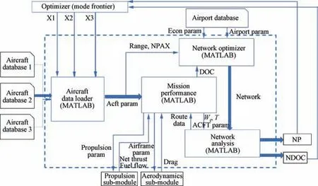
Fig. 2 Airplane/network integrated optimization framework.

Table 1 Airframe parameters - Fuselage.
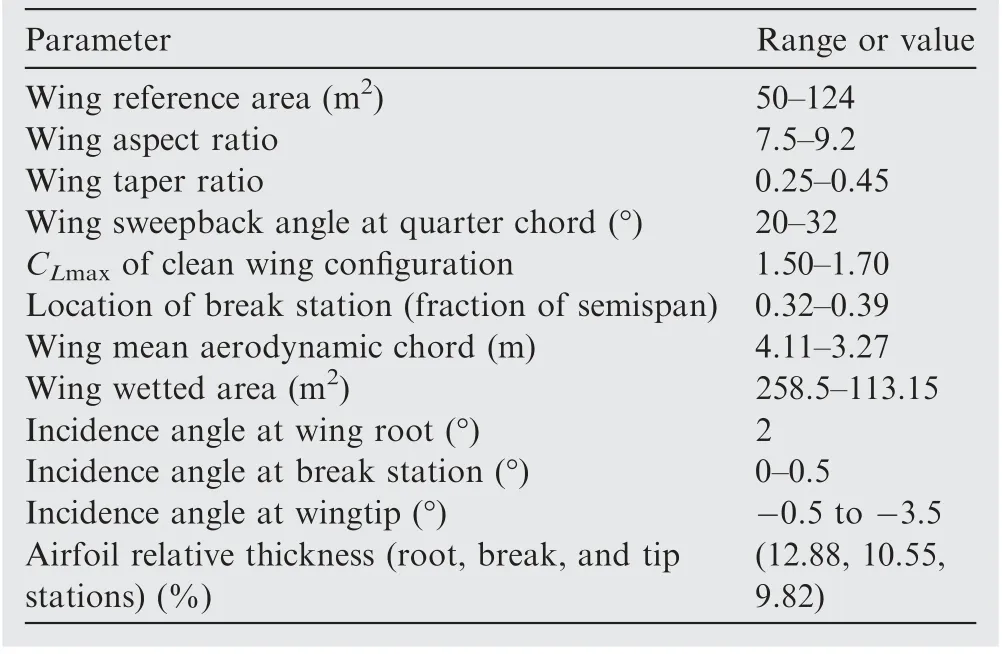
Table 2 Airframe parameters - Wings.
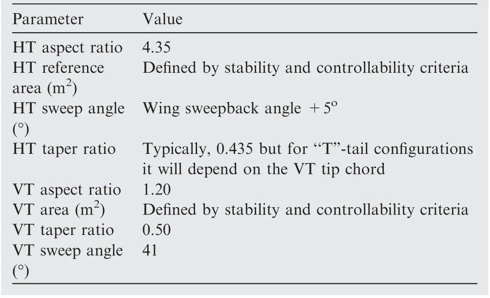
Table 3 Airframe parameters of HT and VT.
During the database generation,MTOW,Maximum Landing Weight(MLW)and Operational Empty Weight(OEW)of each aircraft are calculated through an iterative process asillustrated in Fig.3.In this calculation,weight of pylons,fuselage, empennage, systems, landing gear and engines are calculated separately using empirical formulas.9,47The wing weight is calculated by sizing the wingbox to withstand aerodynamic loads calculated with a full potential code in some few maneuvers in the flight envelope;the secondary structure is estimated by empirical methods.All these weights are considered for the determination of the Operational Empty Weight(OEW).With the weight of each component, it is also possible to obtain the Center of Gravity (CG) of the aircraft and its variation with fuel consumption and different payloads. The MTOW and MLW are then estimated interactively using the mission analysis module and the calculated OEW for the given design range.45
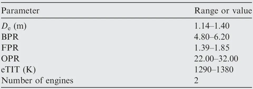
Table 4 Powerplant parameters.
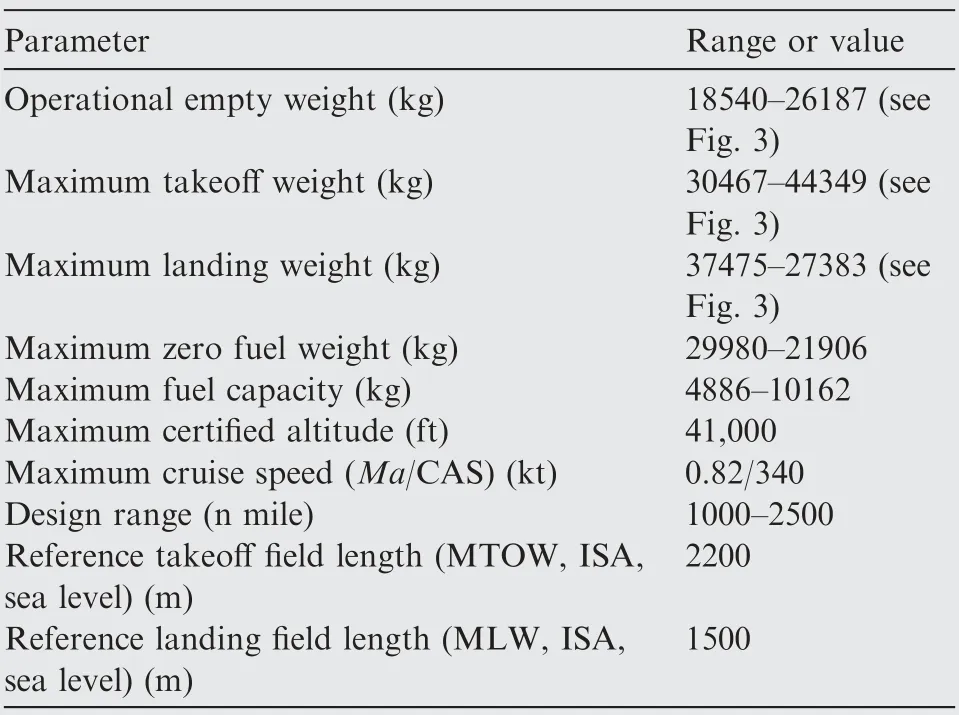
Table 5 Certification parameters.
The network optimizer module generates the design variables (X1, X2, and X3). These continuous variables are numbers varying from 0 to 1, representing the airplane address in each of the three databases. After the aircraft are chosen, the aircraft loader module reads the aircraft and engine characteristics, which are used as input for the mission performance module. The only constraint enforced at this point is that of passenger capacity differentiation by five seats among the three airplanes. This ensures that similar aircraft in capacities are not selected,promoting more diversity in solutions.This module provides to the network optimizer NDOC and NP values.The multi-objective MOGA-II algorithm48is chosen as optimization engine thanks to its robustness and ability to handle global minima or maxima inside a complex design space built with many variables. This first-generation evolutionary algorithm is designed to use inherent genetic operators (crossover,mutation and selection) combined with parenting elitism,which means that it always favors individuals with better fitness values than its parents. The algorithm was set to run 20 generations, with 50% probability of crossover, 5% probability of selection and 1% probability of mutation. The uniform Latin hypercube sampling method14is used to generate the starting points for the GA optimization.In this study,20 individuals are initially created to compose the starting population of the process.
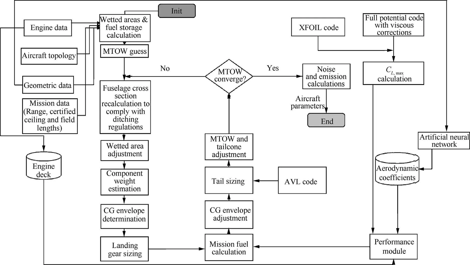
Fig. 3 Flowchart of airplane calculation including key mass figures.
It is worth mentioning that for everyone in the GA population, given by the triplet (X1, X2, and X3), an optimum network is found in a secondary optimization task, where a linear programming problem is exactly determined with appropriate LP solver.49The linear programming model has for objective to determine the configuration presenting the maximum profit,based on the calculated demands,aircraft characteristics, passenger capacity and design range.
Extended explanations related to the implementation of each module and sub-modules shown in Fig. 2, are provided in next sections.
3.1. Network optimizer
Provided the airplane triplet (X1, X2, and X3) is known, the optimum network, including the necessary frequencies, is solved in a secondary optimization process using a linear programming algorithm. The aircraft allocation (tail assignment and schedule for each frequency) is not considered in the present framework and will be considered in future versions. The airline networks are optimized considering operations within a certain geographical area or a certain market share.For this,it is necessary that passenger demand among airports, average ticket price,aircraft fleet capacity,range,and operational costs be known. Then, an optimized network can be drawn up considering the profit maximization. In this context, the profit is maximum if all passengers’ potential demand is fulfilled for each city pair,allocating the necessary frequencies for each aircraft type.Also,it is assumed that the airline allows passengers to buy tickets for maximum two stops between origin and destination, meaning that three types of services are possible: (A)non-stop flights, (B) one-stop connecting flight and (C) twostop connecting flights. In fact, this is a common policy practiced by the Brazilian domestic airlines nowadays.
The optimization algorithm in this module is derived from the Linear Programming Model (LPM) proposed by Sun and Smith11for generic network determination considering passengers fractional flow. A MATLAB® code was developed to set up and solve this problem using the LPM solver available for this application.The mathematical formulation of the problem is presented in the next paragraphs.
Let Xiltjbe the fraction of the passenger’s demand flow fijfrom origin i to destination j,served by a two-stop connecting flight through cities l and t, Yijkthe number of aircraft type k used in the route from city i to j,p the average fare per passenger ($), ckthe average operational cost ($/n mile) at design range, bkthe passenger capacity of aircraft k, LFrefthe reference load factor,and dijthe distance between origin and destination airports. The following integer linear programming model is proposed:

subject to

where Xitj,Xiiltjare positive and Yjkinteger positive for all i ≠j
The average operational costs (ck) for each aircraft fleet,necessary for the optimization, correspond to the direct operational costs related to the design range mission.The objective function Eq.(1)is set to maximize the network profit,based on the difference between the average fare(p)and the average cost per passenger. Constraint inequality (2) states that the fractional flow on route ij cannot exceed the total capacity of the aircraft assigned, while constraint Constraint (3) ensures that the passenger flow from a direct flight from i to j is nonnegative.
It is assumed that 50% of all passenger demand from i to j are derived from direct flights (Xijand Xji), 30% distributed equally among all one-stop flights (Xijt, Xtijand Xitj) and 20% distributed equally among two-stop flights (Xltij, Xijltand Xiltj). Passengers potential demand between origin and destination (fij) is determined via gravitational model, based on city pair distance and econometric parameters. Let P be the city pair population product (P=Pi‧Pj), C the city pair airport catchment area product (C=Ci‧Cj), B the city pair combined buying power index (B=Bi+Bj), G the city pair GDP product (G=GDPi‧GDPj) and dijthe reference distance of the city pair. The following passenger demand model is proposed as follows:

In Eq.(4),the exponents K0,K1,K2,K3,K4and K5are calibration constants, determined by log-linear regression. They may be easily calculated using the public econometric data available (Pi, Ci, Biand GDPioften published by economic agencies).
3.2. Mission performance
This module is the most important part of the optimization cycle since it is where all calculations necessary to determine trip fuel(Wf)and trip time (T)are performed. These variables are essential to compute Direct Operational Cost (DOC) for each route(arc)determined by the network optimization module. Inputs from the aerodynamics (CD) and propulsion (net thrust - Tnetand fuel flow - FF) sub-modules are necessary for solving the mass point equations at time integration steps,for given performance state (weight and environmental conditions at altitude)and operational flight profile constraints.The vertical flight path is constructed numerically integrating the following set of equations of motion50regarding the variables V, γ and Hp:


In steady state and at small flight path angles γ (absolute value<5°, typical for commercial airplanes), Eqs. (5) and(6) lead to:

where fac, is the so-called acceleration factor, is defined according to vehicle’s speed and altitude as follows:50
For constant Mach number below tropopause:

For constant Ma number above tropopause:

For constant Calibrated AirSpeed (CAS) below tropopause:

For constant CAS above tropopause:

with

In addition, the total fuel consumption is calculated as the resulting integration of the fuel flow (obtained from the propulsion sub-module) along all flight path according to

Environmental conditions (pressure, density and temperature)at each integration point,which steps are evaluated every one second along the trajectory,are calculated as per the International Standard Atmosphere isentropic model.51Zero wind,standard atmospheric pressure and 10°C ISA deviation from standard temperature are assumed in this study. Tropopause lower pressure altitude limit is assumed fixed at 11 km pressure altitude. The mission profile computation considers a realistic jet transport airliner operational profile as shown in Fig. 4,according to the following segments:
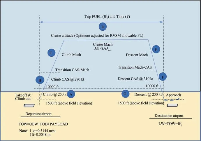
Fig. 4 Mission profile.
(1) Segment A(Climb to 10000 ft(1 ft=0.3048 m)). From pressure altitude of 1500 ft above the elevation of the most used runway for takeoff the aircraft climbs maintaining maximum climb thrust and constant calibrated airspeed of 250 knots(1 knots=0.5144 m/s)(respecting Air Traffic Control speed restriction rules52until a pressure altitude of 10,000 ft. Fuel and time quantity allowances are added to computations representing the aircraft maneuvering necessary for takeoff run, lift off and gear/flap configuration changes.
(2) Segment B (Climb with constant CAS). At 10,000 ft pressure altitude the aircraft then accelerates in a levelled segment to a calibrated airspeed of 280 knots and then climbs at maximum thrust maintaining this speed until the Mach-Crossover Altitude or Cruise Altitude,whichever is lower. The Mach-Crossover Altitude is the pressure altitude where the number of Mach reaches the prescribed climb cruise Mach number.
(3) Segment C (Climb with constant Mach to cruise altitude). From the Mach-Crossover Altitude the aircraft climbs at maximum thrust with constant number of Mach (calculated cruise Mach number) to the selected cruise altitude.
(4) Segment D(Cruise at optimum altitude and Mach number). The cruise altitude corresponds to the optimum cruise altitude adjusted to the suitable flight level as per the Reduced Vertical Separation Minima (RVSM)air traffic rules.53To select the correct flight level, the average magnetic course between origin and destination airports is computed according to hypersine geodesic formulae.54The optimum cruise altitude is calculated as the minimum of: maximum certified ceiling (fixed as 41,000 ft in this study),maximum specific range altitude(considering the selected cruise speed and takeoff weight), maximum altitude where the residual rate of climb is 300 ft/min, and the maximum altitude where a 30% margin to stall is achieved. The latest considers stall at 40°bank angle in clean configuration and is calculated according to ICAO50
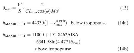
The cruise segment is performed at constant number of Mach that is derived from the maximum
(5) Segment E (Descent with Constant Mach to Mach-Crossover Altitude). From top of descent, the aircraft descents at idle thrust with cruise Mach number to the Mach-Crossover Altitude, where a calibrated airspeed of 310 knots is reached.
(6) Segment F (Descent with Constant CAS to 10000 ft).From the Mach-Crossover Altitude, a constant calibrated airspeed of 310 knots is maintained in the descent flight at idle thrust to 10,000 ft pressure altitude where the airplane is decelerated in leveled flight to a calibrated airspeed of 250 knots.
(7) Segment G(Descent to 1500 ft).From 10,000 ft pressure altitude, constant calibrated airspeed of 250 knots is maintained in the descent flight at idle thrust to 1500 ft pressure altitude above the landing runway elevation where the airplane initiates the approach and landing phase. Fuel and time quantity allowances are added to computations representing the aircraft maneuvering necessary for approach, gear/flap configuration changes and landing.
The total Fuel On Board (FOB) is determined considering the minimum fuel required to comply with Brazilian regulations(RBAC 121.64555)for jet transport aircraft,representing the sum of the following quantities:
(1) Fuel necessary to fly from origin to destination airport(Wf) considering the operational profile described before.
(2) The fuel required to fly from destination to alternate(or diversion)airport considering the given operational profile. In this study, the alternate airport is chosen as the closest airport from the destination airport in the network, considering that all airports in the company network have the capacity available and handling infrastructure to absorb the demand (WfAlternate).
(3) Fuel burn related to 10% of the trip time determined in(1) to be used as contingency for route deviations and adverse weather conditions (WfContingency).
(4) Consideration of 30 min holding at 1500 ft height over the alternate airport elevation at suitable holding speed.In this study, the holding speed is selected as the maximum L/D speed or 1.3 g margin to stall speed(ensuring a protection of 44° maximum bank angle to stall) in clean configuration, whichever is higher, considering weight estimated at the alternate airport.
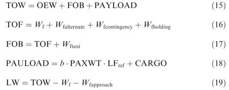
Considering the statements above, Eqs. (15)-(19) are used in the mission performance calculation algorithm with the objective to determine trip fuel (Wf). They consider all elements necessary to determine the takeoff weight (empty weight,fuel on board and payload)and landing weight at each sector56:
In addition,payload-range diagram related limitations shall be respected when considering mission performance calculations.56Eqs. (20)-(22) show the takeoff weight constraint equations related to maximum takeoff weight, maximum zero fuel weight, maximum landing weight and maximum fuel capacity:56


The trip fuel and time determination routine were elaborated considering that aircraft departs with a certain Takeoff Weight (TOW) at the departure airport. The airplane trajectory is the top combination of the climb, cruise and descent flight phases.An interactive algorithm is implemented to determine top of descent point as shown in Fig. 5. The algorithm starts computing the top of descent over the destination airport,computing all cruise phase up to there.Then the descent distance is determined from this point and subtracted from the cruise phase,determining a new top of descent.A new computation cycle is then computed from this point, determining a new descent distance. The process is repeated until the difference between the descent points on subsequent runs is less than 0.5 n mile.
In addition,it is necessary to adjust the TOW,also through an iterative process, considering payload-range envelope checks (MZFW, MLW, MAXFUEL and MTOW) as shown in Fig.6.In this cycle,the alternate fuel calculation(Wfalternate)is computed considering the TOW as estimated landing weight minus a go-around fuel allowance at the destination airport.
The Direct Operational Cost (DOC) computation is also performed in the mission performance module and provided as output to the computation of the total network DOC. In this process, the single mission DOC is determined using empirical formulae expressed as function of Maximum Takeoff Weight (MTOW), trip time(T), trip fuel (Wf) and crew number.47Five types of cost components are calculated to compose the DOC in each sector and added according to

3.3. Mission analysis
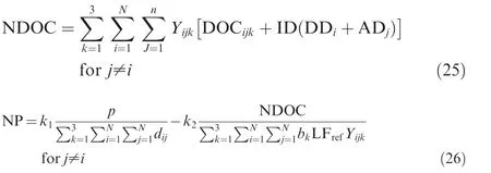
In this module, the key results related to all air transport networks and all fleets of airplanes are aggregated.The computations of total Network Profit (NP) and total Network DOC(NDOC) are done via Eqs. (25) and (26), as function of route frequencies(Yijk),departure and arrival delays(DDiand ADj),average delay cost per minute (ID), sector distance (dij), aircraft passenger capacity (bk) and average ticket price (p) as follows:
In addition, the fleet size required in each aircraft type k may be estimated as function of sector block time (TBij) and average Daily Utilization (DU) according to:

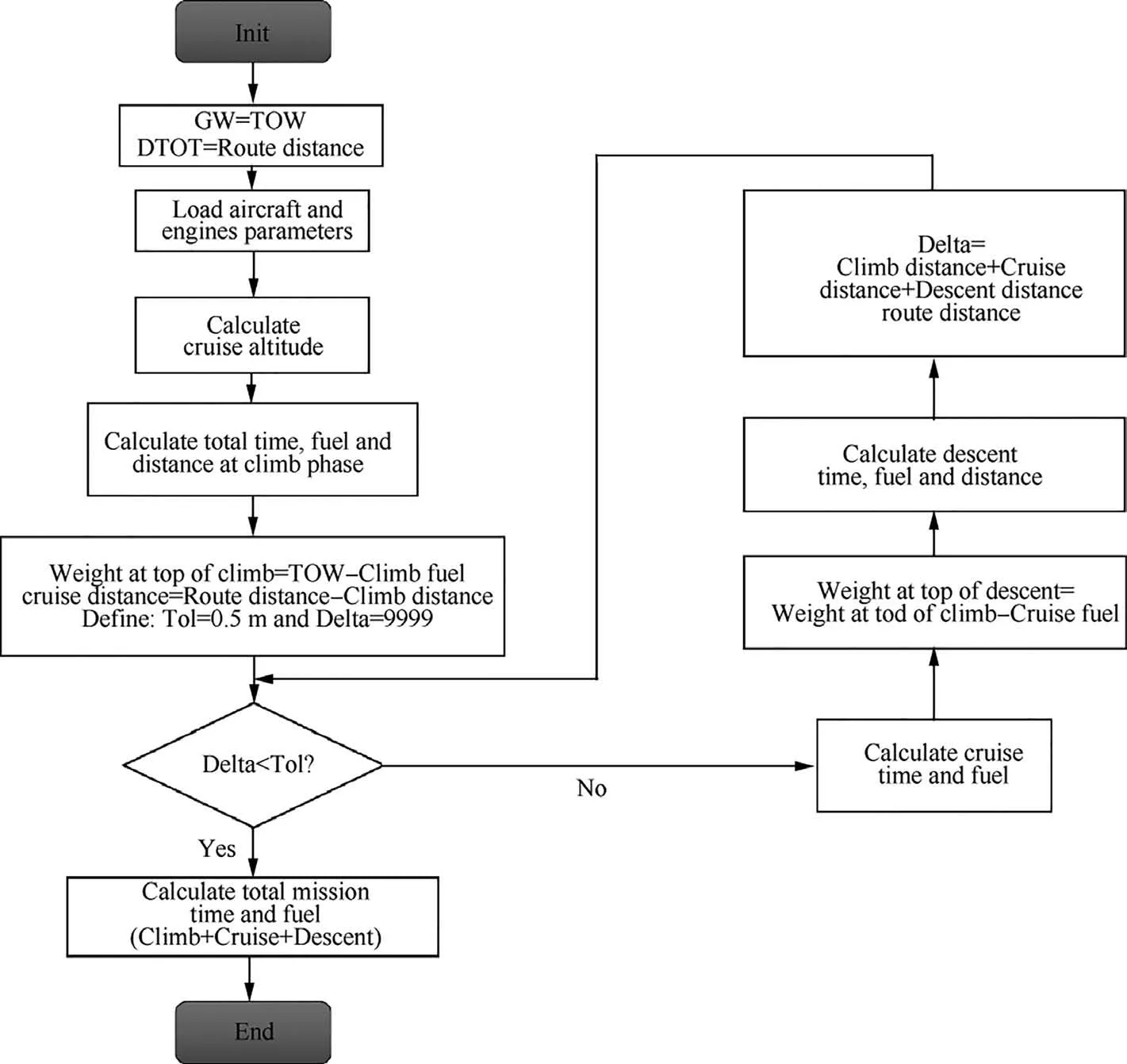
Fig. 5 Flight profile workflow for calculation of trip fuel and time.

Fig. 6 Complete mission calculation algorithm.
3.4. Propulsion
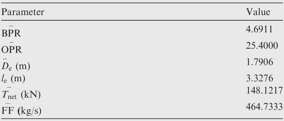
This routine is responsible for computing the Fuel Flow (FF)and=Net Thrust (Tnet) necessary for performance calculations at the flight phases. It is based on the thermodynamic model proposed by Thomas57on turbofan engine operations.The program code is adapted from open source code(Engine-Sim application) developed by NASA Glenn Research Center,58improved by Mattos et al.45The output parameters from the computation are FF, Mach number, ISA deviation,compressor pressure ratio, fan pressure ratio, fan diameter,turbine inlet temperature, and throttle position. The classical one-dimensional thermodynamics modeling is the basis of the calculation procedure embedded in the code. Two calculation steps are built in the module:(A)the design step where all engine characteristics are raised at a given design point(cruise Mach number, cruise altitude and 95% throttle setting) and(B)the analysis step,where it is possible to calculate the engine thrust and fuel flow rate from the geometric characteristics obtained in the design step. In this sub-module, the engine weight, used in the component weight estimation process shown in Fig. 3, is also computed. Most of the engine weight estimation methods used in academy59are derived from empirical formulae,60,10based on data from first- and secondgeneration jet engines. Such methods may not be applicable to the current generation of engines, which are much different in design, applicable to the aircraft used in the proposed optimization framework.Thus,a new method for turbofan engines weight estimation was elaborated and applied to the design of airplanes in the present work. Eq. (29) shows the kind of parametrization and variables considered to model the turbofan engine weight.

The coefficients and exponents of Eq. (29) are obtained by optimization using a genetic algorithm with the minimization of mean square error in regard to known engines.61These engines belong to a database comprised of over 25 engines with considerable thrust variation among them, covering a large variety of turbofan designs.62Table 6 shows the coefficients and parameters obtained with the optimization process.Table 7 shows the average parameters used for normalization.Table 8 contains weight estimation errors for some known turbofan engines. The maximum error obtained was 6.48%,which is considered very good for the scope of this study.
3.5. Aerodynamics
The aerodynamics module computes the total drag (CD), lift,and moment coefficients that are required for performance calculations at many points within the mission profile. A surrogate model based on artificial neural network is employed for the estimation of aerodynamics coefficients and it is exten-
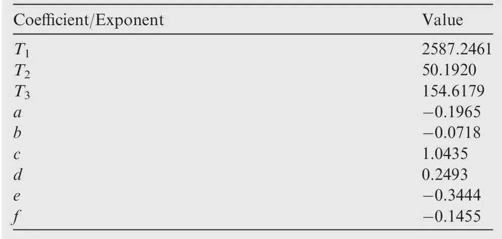
Table 6 Obtained exponents and coefficients for Eq. (29).
Tsively described by Secco and Mattos.46Among many architectures that were evaluated, the multilayer feed-forward ANN was found to be best suited for non-linear problems with dozens of variables as is the present case.This type of network can approximate any function to any desired degree of accuracy, provided it has enough neurons in the hidden layers.
able 7 Parameters used for normalization in Eq. (29).
Regarding estimation of drag coefficient, three dedicated ANNs were designed to estimate the three drag components,zero-lift,induced,and wave drag.This resulted in considerably more accuracy than the approach of employing a single ANN for the drag estimation task.
Approximately 110,000 different wing configurations were employed for training and validation purposes.For the generation of the database of this size, a full potential aerodynamic code was used. The potential module is coupled with an integral boundary layer program that calculates the viscous effects at prescribed stations along wingspan.
The accuracy of drag estimation by the ANN system proved to be outstanding,recording an average error of 3 drag counts in high-Mach regimes when compared with the results from the full potential code.This is typically the error obtained with flight test data and those from large subsonic wind tunnels. If the flow is subsonic over the entire airplane surface,the average estimation error of the ANN lies below 0.1 drag counts.Input for the computations are wing geometric parameters such as aspect ratio,leading-edge sweepback angle,taper ratio, incidences, dihedral angles, location of the trailing-edge break station as well as airfoil parameters from three wing stations.An additional 3%on total CDis applied to consider miscellaneous drag. Induced drag is adjusted for the presence of winglets as per the study of De Mattos et al.63
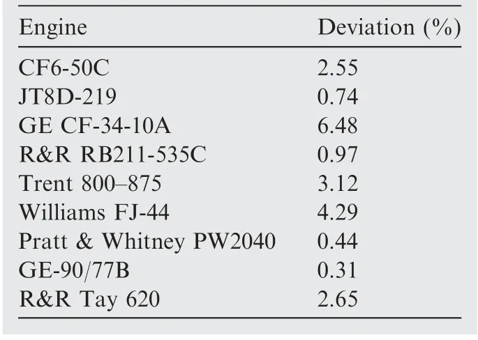
Table 8 Mass error estimation for some known engines.
A verification of the accuracy and capability of the ANN estimation of the drag divergence is shown in Fig. 7. Two airplane configurations were selected from the database for further analysis (not part of the ANN training set) presenting different drag behavior over Mach number. Fig. 7 shows that the delay of the drag divergence with the increase of the wing sweep angle was correctly captured by the drag-predictor ANN for the two configurations.
In addition, an airliner with 93.5 m2wing reference area,designated ITA107, was also chosen to evaluate the accuracy of the designed ANNs in predicting drag and lift coefficients.Wing geometric characteristics and flight condition information are given in Table 9. The three-view of the airplane are shown in Fig. 8.
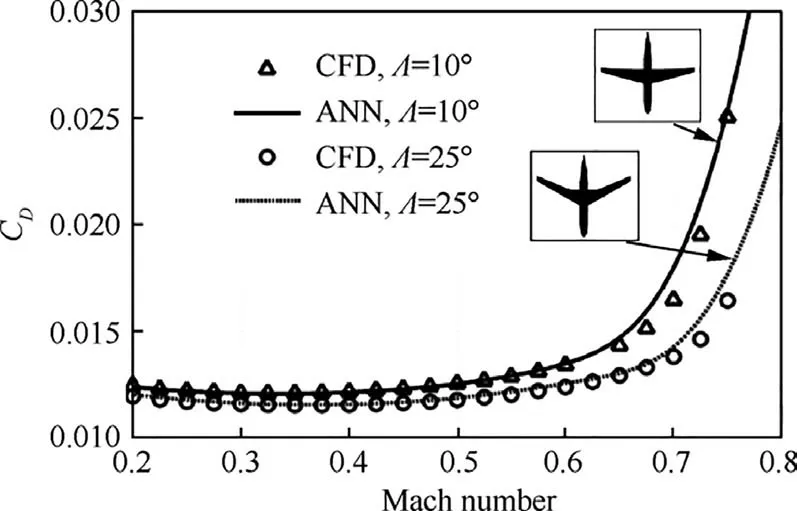
Fig. 7 Comparison between ANN overall drag predictions and CFD results for two airplanes with different wing sweepback angles (Altitude=10.5 km, α=1o.).
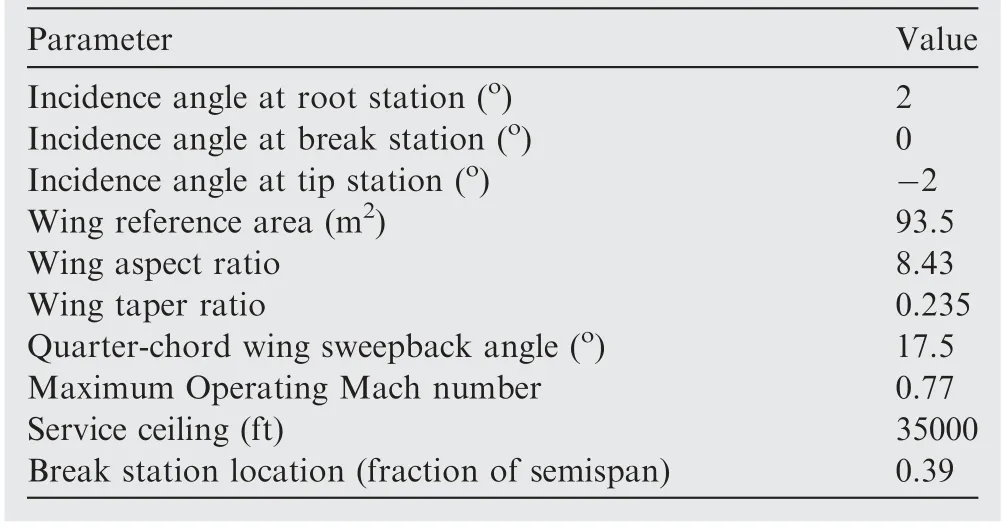
Table 9 Characteristics of ITA107 airliner.
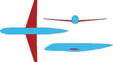
Fig. 8 Three-view of airliner considered for a test case.
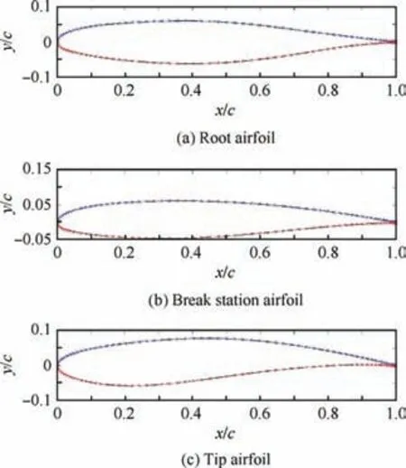
Fig. 9 Wing airfoils of ITA107.
The coordinates of the three basic airfoils used in the wing definition of the airplane under consideration were read from files.Airfoils of the root,break,and tip stations present a maximum relative thickness of 12.3%, 12.3%, and 10.9%, respectively. There is then a need for an optimization problem to fit Sobieczky polynomials to these geometries. This was carried out with the fsolve optimization tool from MATLAB®.Fig. 9 shows the original wing airfoil geometries and polynomial fittings. Some small discrepancies exist between the original and calculated geometry of the tip airfoil (vertical and horizontal dimensions are normalized regarding the mean aerodynamic chord of each airfoil).
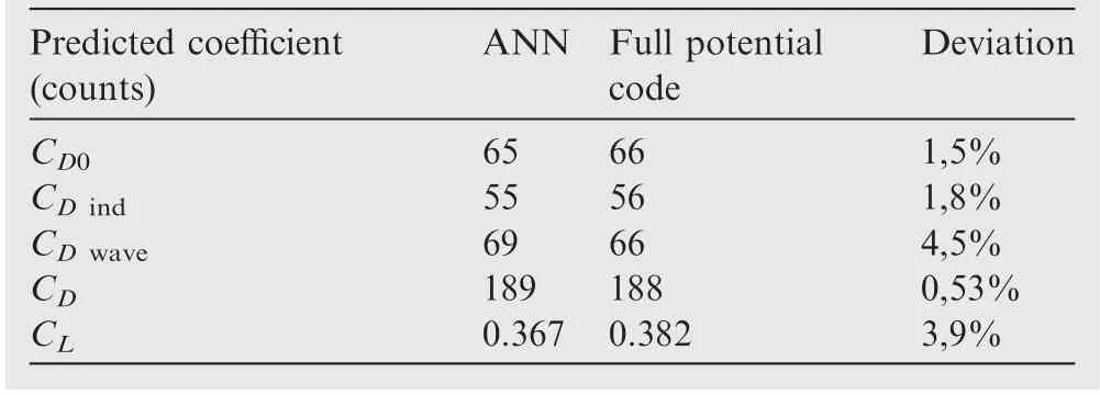
Table 10 Predicted and calculated coefficient values by ANN and full potential code.
Table 10 shows a comparison between the ANN and CFD results. The overall drag differs by one drag count only. The wave drag coefficient recorded the highest difference between the neural network and the full potential code, which was of three drag counts.The ANN drag estimation provided average error of 3 drag counts when compared with the full potential code results. At the Mach number of 0.77 and 1° angle of attack, the streamlines on the wing upper side as calculated by the full potential code indicate attached flow close to the fuselage and at the wingtip. However, there is a separation region close to the trailing edge along a great portion of semispan, caused by shock waves. It is observed that in some wing parts the flow experiences a reattachment to wing surface and suffers another separation. This is indeed a complex flow pattern, which was well captured by the ANN prediction. This example is an excellent boost for the ANNs designed in the present work. Despite the complexity of the airflow at the cruise condition over the test case airliner,ANNs could predict the drag coefficients.
High-lift systems have a major influence on the sizing,economics, and safety of transport airplanes. Although high-lift systems are complex and costly, they are a necessity to allow airplanes to take off and landing on runways of acceptable length without penalizing the cruise efficiency significantly.64Several analytical methods that both account for stall effects and enable the prediction of the maximum lift coefficient were discussed and a trade-off between the methods was conducted.65From this trade-off,it was found that both the pressure difference rule and the so-called ‘‘critical section” are good option in terms of accuracy and versatility. The critical section method was incorporated in the present design framework. The XFOIL panel code66for determining an airfoil’s maximum lift coefficient for a set of wing sections was combined with a wing-fuselage full potential code with viscous corrections for the estimation of maximum lift coefficient of the clean-wing configuration.67
4. Case study
The case study determines the optimum air transport network within a wide operational area in Brazil covered by its twenty major airports.Distances dij(used in the network optimization module) and true headings Θij(used in the mission analysis module) between city pairs are determined via haversine formula for loxodromic routes,68according to
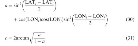


where R is earth’s average radius, assumed as 3458 n mile
A bias of 3%is applied on all great circle distances to accommodate airway-route differences. Tables A1 and A2 (see Appendix A)show the calculated route distances and true headings between airports.The airport data used in the mission analysis computations was extracted from the Brazilian Aeronautical Information Publication (AIP).69Tables A3 and A4(see Appendix A)show the airport data and associated city econometric parameters used in the gravitational model. It is assumed that the airline operating this network has 20%of passenger market share and does not actuate in the cargo segment.Table A5(see Appendix A)shows the estimated daily passenger demand, considering this share. The proposed demand model(see Eq. (4)) was calibrated using the city pair demands data related to the 20 busiest Brazilian routes in 2014, 2015 and 2016, extracted from the Brazilian Civil Aviation Authority(ANAC) statistical reports.70A log-linear regression model was applied to calibrate the exponents for the proposed equation. Values obtained were: K0=3.5770, K1=0.4157,K2=-0.0388, K3=-0.1643 and K4=0.1331. The Pearson coefficient associated with this regression was 0.63, which was considered reasonable for air transportation analysis.Average delays at each airport are considered by the model proposed by Newell71as function of runway configuration and capacity:for departure delays,which occur on ground,10 minutes for airports with two or more active runways(for SBGR,SBGL and SBBR) and 5 minutes for airports with 1 active runway (for SBCT,SBPA and SBSV).Arrival delays,associated with terminal holdings and cruise speed reductions, are assumed to be 5 minutes at airports with two or more active runways and 3 minutes for airports with one active runway. Airline operational parameters assumed in this study are listed in Table 11. Also,the revenue to ticket price ratio (k1) and cost to DOC ratio(k2)are assumed as 1.1 and 1.3 respectively.
A reference airplane was selected for comparative analysis(see Fig. 10). It is a two-engine airliner featuring underwing engine configuration and it can accommodate 76 passengers in a single class at 32 inch seat pitch.It is designed for a range of 2000 n mile, carrying full passenger load and cruising at 35,000 ft at Mach 0.78.The main configuration characteristics are shown in Table 12.
5. Results and discussion
Exactly 528 generations were part of the simulation carried out with the genetic algorithm MOGA-II already implemented in modeFrontier®. Fig. 11 shows the feasible individuals from the optimization run and the resulting Network Profit (NP)as function of Network DOC (NDOC). Individuals that maximize NP with the lowest possible NDOC are marked in green in a Pareto-type front presentation.The unfeasible individuals,marked in yellow cross, correspond to the designs where aircraft selected in different groups have close passenger’s capacity (within 5 units range) and therefore are not considered in the analysis. Table 13 shows relevant characteristics of the 11 individuals in the front resulted from the optimization task.Main network and aircraft design characteristics are displayed for reference (MTOW, wing area, aspect ratio, engine by-pass ratio and engine fan diameter).
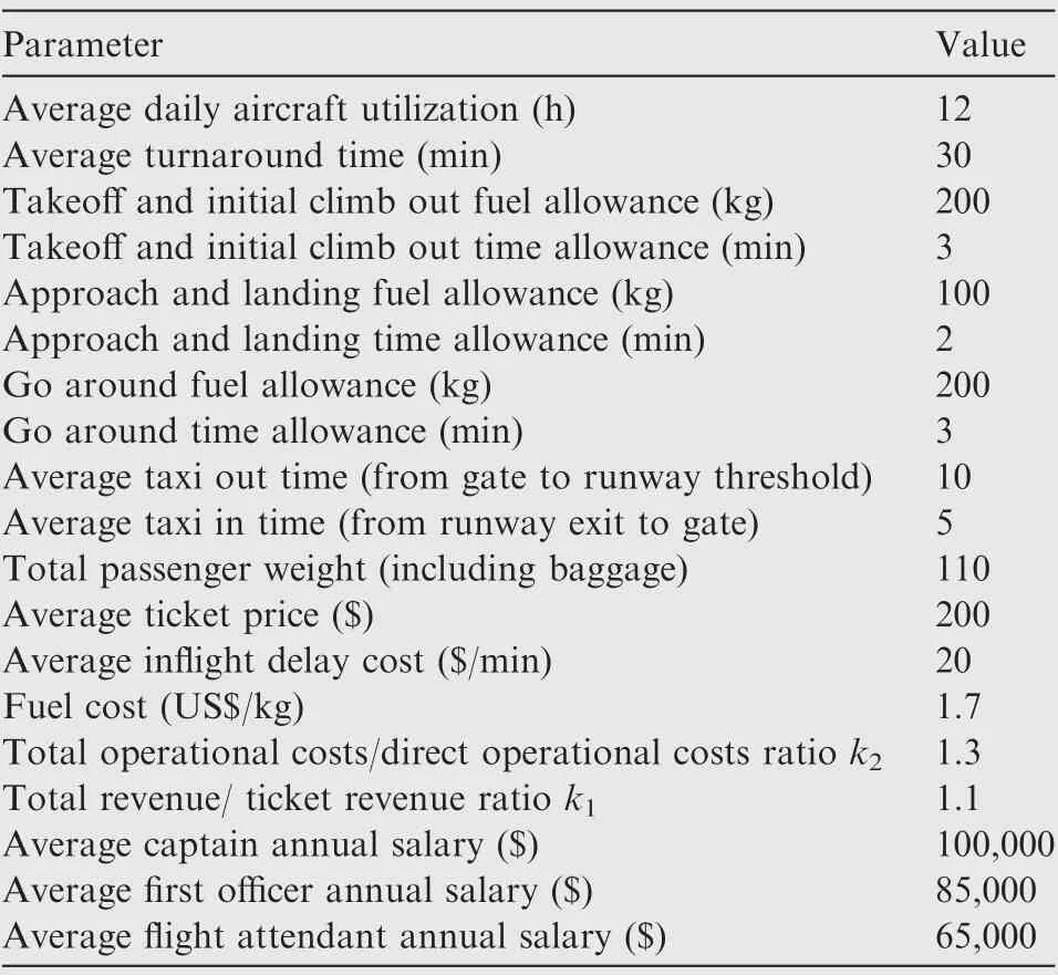
Table 11 Airline operation parameters.
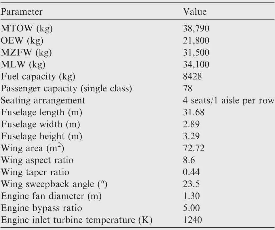
Table 12 Baseline airplane characteristics.
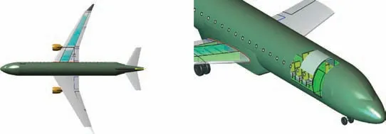
Fig. 10 Reference airplane illustration.
Table 14 presents the main statistics of the Pareto-type front,showing the variation of each fleet when compared with the baseline aircraft. It is noticeable that average aircraft selected in the three fleets present significantly lower ranges than the baseline, which suggests that the last one may not be the optimal design for the region in study. The Pearson’s correlation matrix is shown in Fig. 12 considering the design variables related to the Group 1 fleet and objective functions.The correlation coefficient,shown on each cell of the matrix,is a measure of the linear correlation between two pairs variables in the whole dataset, calculated as the covariance of the two variables in all designs divided by the product of their standard deviations.It ranges between+1 and-1,where 1 is total positive linear correlation (red color cells), 0 is no linear correlation, and -1 is total negative linear correlation (blue color cells).
As expected,the higher positive values for MTOW are registered by wing area, design range, and number of passengers.Concerning the main objective function, it is noticeable that network profit presents the strongest negative dependency on range and positive dependency on number of passengers,meaning that the model captured the payload-range tradeoff as determinant characteristics on the airline profit.On the Network DOC side,the strongest positive dependencies are found in the variables related to the increase of the weight (therefore increase of fuel consumption)such as MTOW,number of passengers and wing area. These observations are also applicable to Groups 1 and 2 fleets.
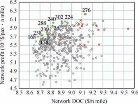
Fig. 11 Pareto-type front and dominated individuals.
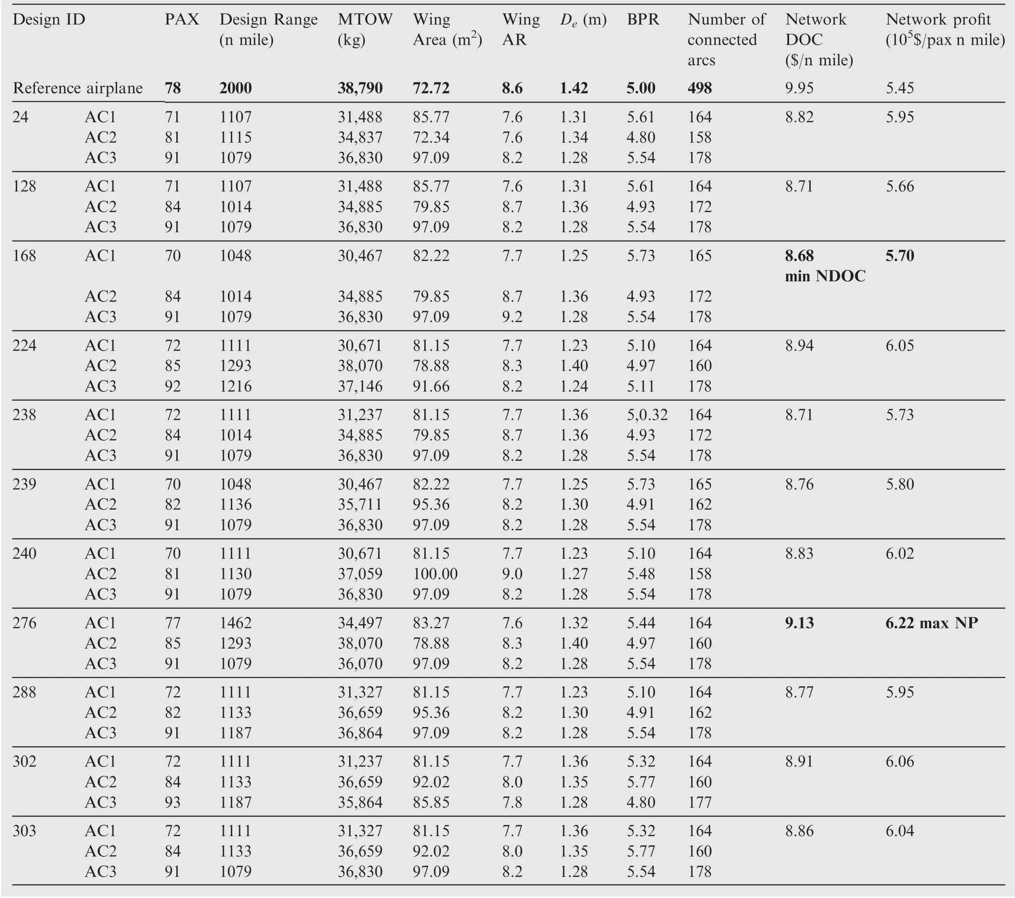
Table 13 Individuals selected in Pareto-type front resulted from optimization task.

Table 14 Pareto-type front statistics.
The Pareto-type front data shows two remarkable design extremes: maximum network profit (design #276, 6.22×10⁻⁵$/ pax. n mile) and minimum network DOC (design #168,8.68 $/n mile). Figs. 13 and 14 show the resulting routes from the maximum network profit and minimum network DOC for the three fleets respectively. It may be noticed that the aircraft with lower capacities presented similar route structures in both scenarios. This may be verified on Tables B1-B3 and Tables B4-B7 (see Appendix B) where the resulting frequencies,assigned for each aircraft type on each route, are shown for maximum network profit and minimum network DOC scenarios.Tables B4 and B8 show the common city-pair connections for the three fleets in these scenarios (where one means the existing connection and zero means no connection). In both tables, it may be observed that 154 city-pair connections(40.5%of the total possible)are shared among the three fleets.
The optimization results related to the minimum network DOC scenario are shown in Table C1 (see Appendix C). It can be verified that the best aircraft fleets resulted in design ranges (1462 n mile, 1293 n mile and 1079 n mile respectively)lower than the maximum sector distance possible(POA-MAO/MAO-POA, 1746 n mile). In this scenario,the maximum connected route distance obtained is 1285 n mile, related to the POA-SSA/SSA-POA sectors. This means that the optimum aircraft selected from the database are the ones in which fuel capacity is just enough to accomplish the missions in their related networks. This is the point where DOC minimization objective achieves maximum influence on the optimization process and seeks to not sacrifice fuel consumption (therefore lowering the DOC)on the trade for the incremental number of passenger’s, whose consequence is always the increase structural weights with the fuselage size increase. The reduction of fuel capacity (and therefore maximum range) seems to be the strategy resulted in by the algorithm to hold the structural weight growth as consequence of the increasing number of passengers. In fact, it is observed that all three fleets resulted in lower MTOWs than the baseline aircraft,even though carrying more passengers on fleets #2 and #3. Because of these range limits, to reach the north/northeast cities, the consequent settlement of hub at SSA is identified as a natural accumulator of departures and arrivals. As net effect, it is observed that the total network DOC obtained was -12.8% lower than and the total fleet size was 19.8% higher than the one related to the baseline aircraft. In addition, the cost per passenger dropped by 10.5%, due to increased number of passengers transported in the network.
Results for maximum network profit design scenario are shown in Table C2 (see Appendix C). In this case, the DOC minimization objective also led the effect of reduced design ranges to this extreme, not connecting routes longer than 1079 n mile. As in the minimum DOC extreme, a hub in SSA is also identified to cope with the range limitations of the fleets. However, in this extreme, the influence of profit maximization has a strong push on the optimization process,leading the increase of aircraft capacity for fleets #2 and #3 to #85 and #91 respectively (remaining below the 130-seat boundary). In this case, to accommodate more passengers in the cabin, aircraft designs with wider fuselages are obtained providing 5 and 6 seat row configurations. The net result recorded a relative increase of OEW and slight reduction of design range when compared with the DOC minimization.Network profit in this scenario is increased by 14.2% regarding the baseline aircraft network, also bringing a significant reduction of about -8.2% on DOC. For both extremes, considering that the trip profit is also dependent on DOC,a slight increase on wing areas and wing sweep angle were observed,revealing a trend from the algorithm to improve the specific range. Engines also slightly increased bypass ratios (reaching a maximum of 5.5), to minimize fuel consumption and decrease DOC. In addition, the cost per passenger dropped by 10.6%, due to increased number of passengers transported in the network.
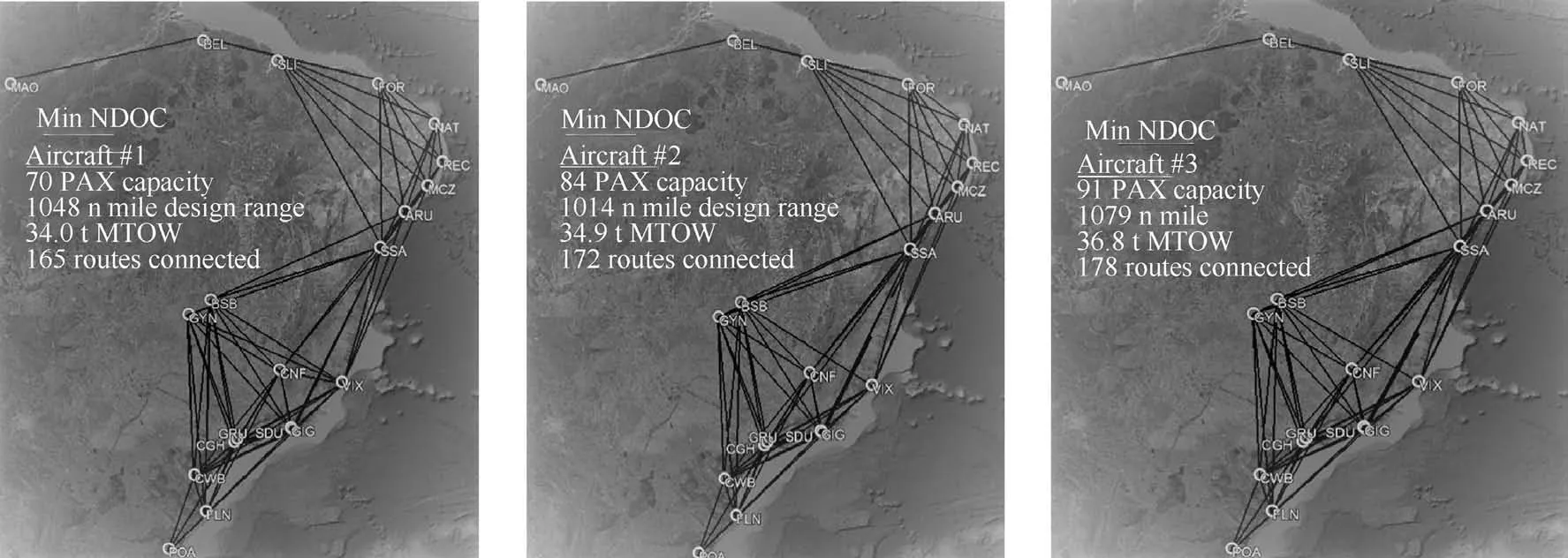
Fig. 14 Routes obtained from minimum network DOC.
It is worth mentioning that in all fleets the wing aspect ratio relays within reasonable boundaries (between 7.6 and 9.2) in the Pareto front designs. In fact, for this class of regional airplanes, with passenger capacity topping 130 seats and maximum 2000 n mile range, no high-tech concept such as extremely flexible wings or truss-braced configurations seems to be necessary. It is also noticeable that most of wing sweepback angles produced are higher than in the baseline aircraft (23.5), suggesting that the average cruise speed, related to maximum Ma‧CL/CDcondition, is faster than the one related to the last one (approximately Mach 0.78). This means that a flight time minimization component, embedded in the DOC optimization, might be pushing the results instead of minimization of fuel consumption.This is a consistent result since all aircraft have the same wing airfoils (including the baseline one) and, at higher speeds, a way to minimize the wave drag is to increase the sweepback angle.
6. Conclusions
An innovative design optimization framework for designing optimal aircraft fleets, composed of three aircraft types, and corresponding networks were presented. The framework maximizes the total Network Profit(NP),satisfying given city-pair passenger demands. A test case was run for a Brazilian aerial network connecting 20 cities.
The goal is to provide an enhanced tool for decision makers to assist in several aspects, such as redesign aerial networks and to properly purchase airplanes tailored to their networks.Optimal airline network covering a certain geographical area integrated with the best suited fleet composed of three airplane types can be determined. Passenger demands among the twenty main Brazilian airports were assigned by a gravitational model.
Highly detailed and realistic airplanes are selected from three databases. A genetic algorithm cares for the maximization of network profit and minimization of its associated direct operating cost. In the calculation process, for a triplet of aircraft,the optimum network is determined in a secondary optimization process using linear programming. The optimum networks present the highest profit complying with calculated passenger demands, aircraft characteristics, airplane capacity and range. A complete mission performance algorithm was designed and is applied with the objective to evaluate fuel burn and time for each sector, essential parameters for the network DOC calculation. An accurate ANN system is employed for the estimation of aerodynamics characteristics,enabling faster simulation times and realistic mission performance calculations. During the optimization process, the aerodynamic and propulsion characteristics of the selected aircraft are driven towards the best specific range, considering the optimized air transport network.
The classical approach on aircraft design frequently considers only the minimization of DOC for a mission.In the present study, it becomes evident that the network profit can be considered a suitable candidate as design objective, if the associated NDOC is contemplated in the analysis, as is the case enabled here by the Pareto-type front presented.In fact,profit is an economic parameter that has been used in the air transport industry as measurement of airline efficiency and has special significance for decisions focusing on financing rather than DOC.However,its maximization leads to bigger aircraft,with increased seat capacities, as can be verified in the Pareto-type front solutions, which may bring other non-operational finance impacts for the airlines, such as increase of inventory costs and airport infrastructure and compatibility issues.
The optimization framework effectiveness was ascertained by analyzing the two extremes solutions of the Pareto-type front. These solutions present 14.2% increase on the network profit and 12.8%reduction on network DOC,when compared with that of the baseline aircraft (78 passengers, twin regional jet transport, 2000 n mile design range).
Finally,we suggest future research be conducted on the network optimization considering a larger number of airports and contemplating a more diverse aircraft database. Noise and emissions constraints for some airports can be enforced without much difficulty.The cruise profile can be improved considering,for instance, step cruise and air traffic control constraints.
Appendix A. Network data
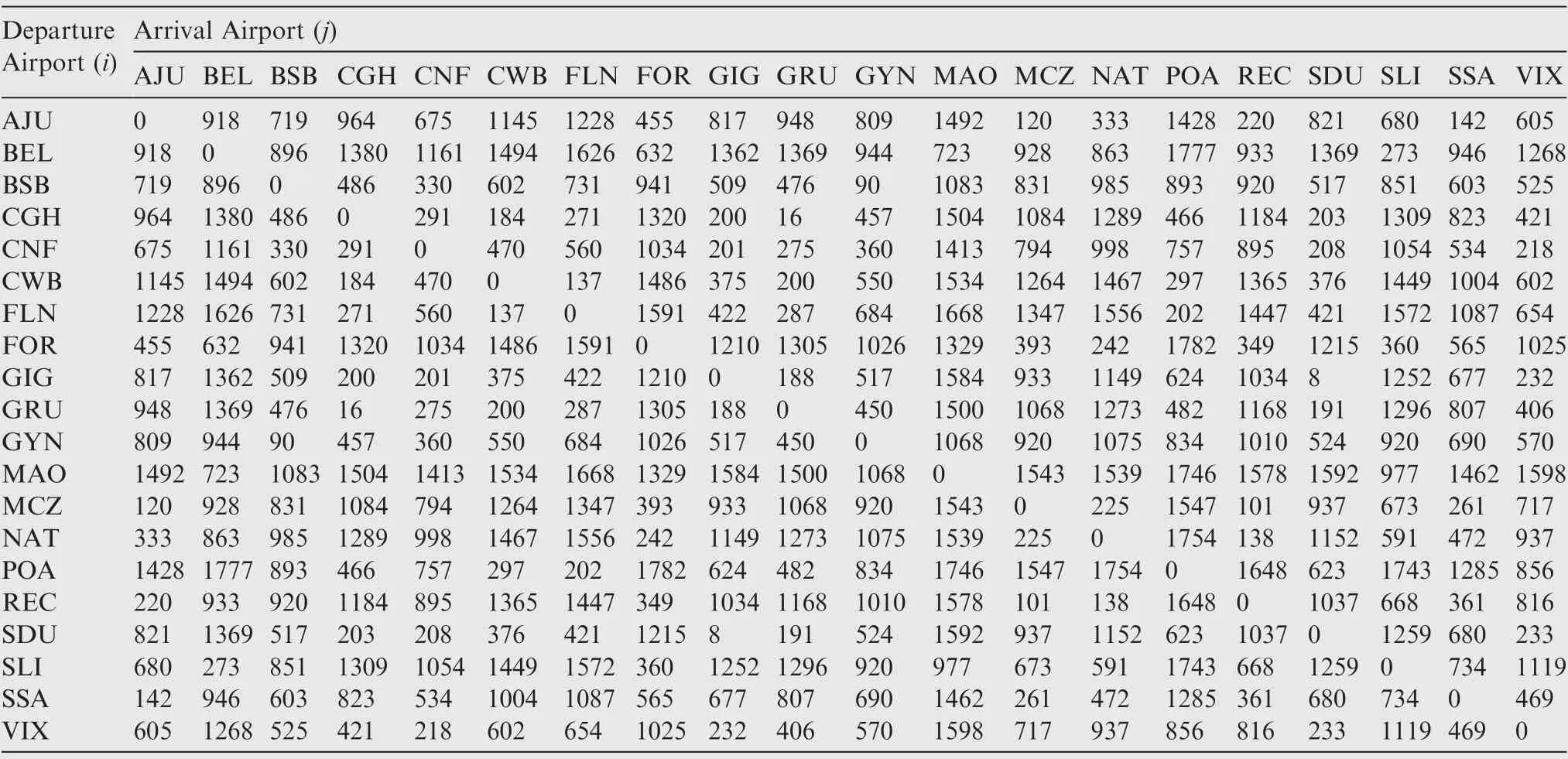
Table A1 Network route distances (n mile).
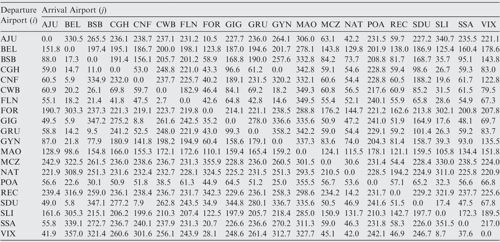
Table A2 Network route true headings -Θij (°).
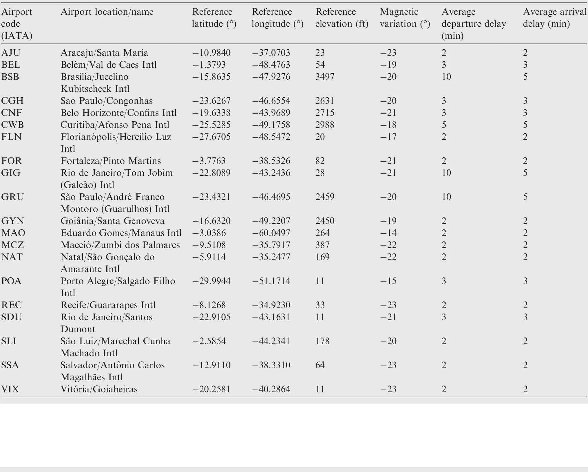
Table A3 Airport data.
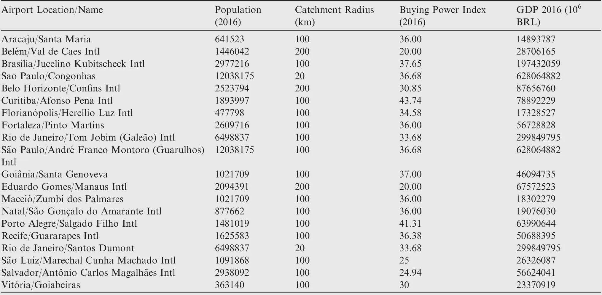
Table A4 Econometric data.
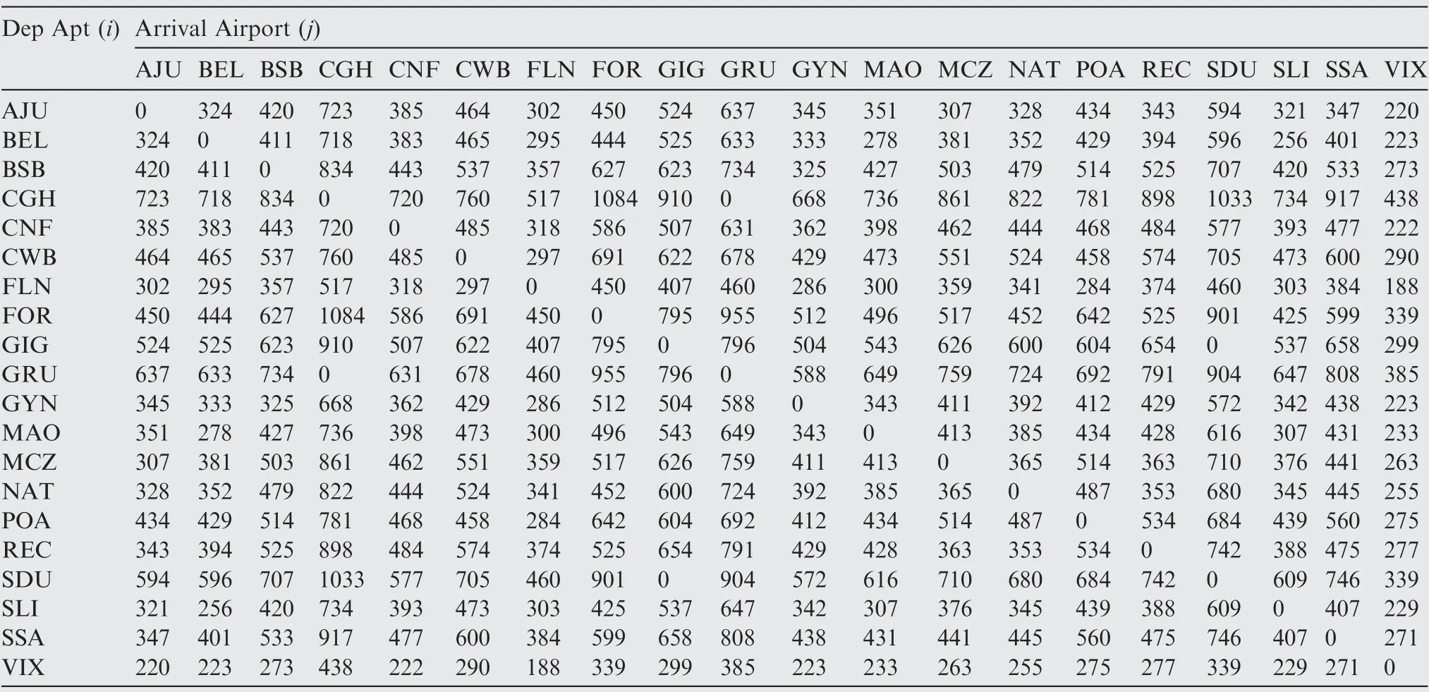
Table A5 Estimated passengers demand per day (20% Market share).
Appendix B. Network frequencies (after optimization)
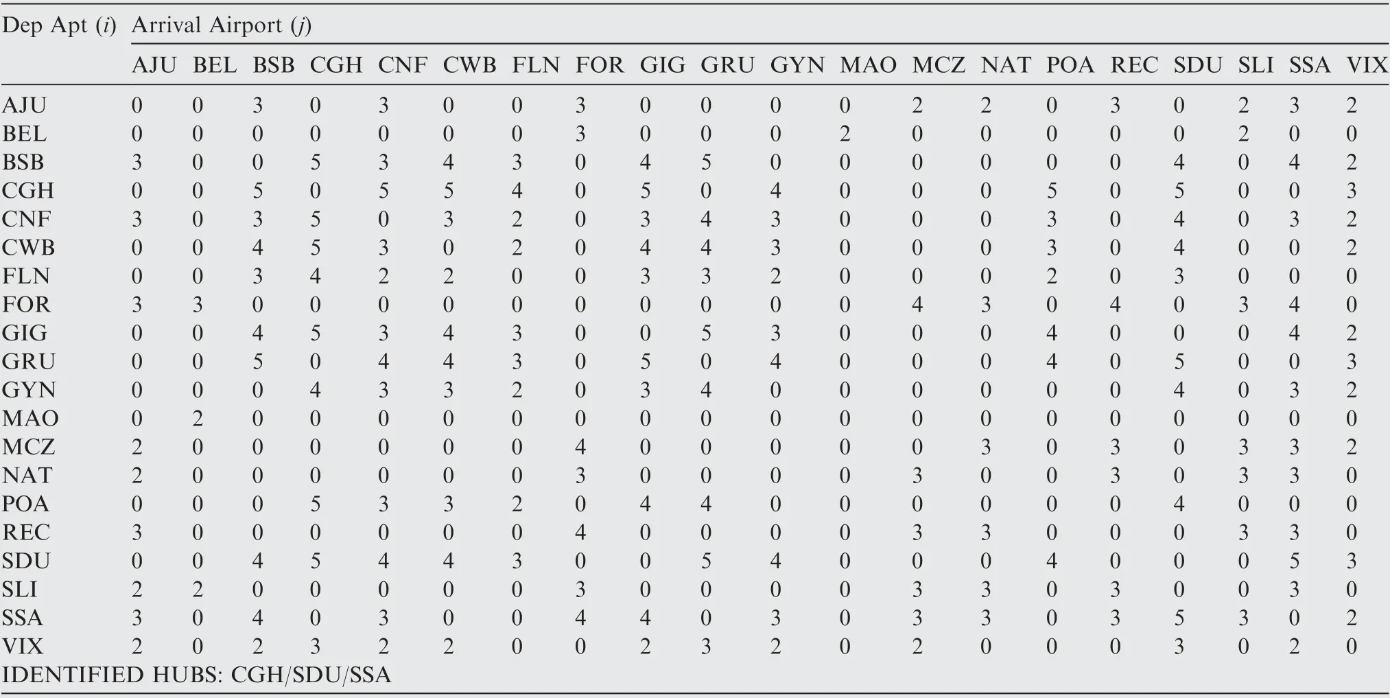
Table B1 Maximum network profit - frequencies per sector (Fleet#1-77 seats).
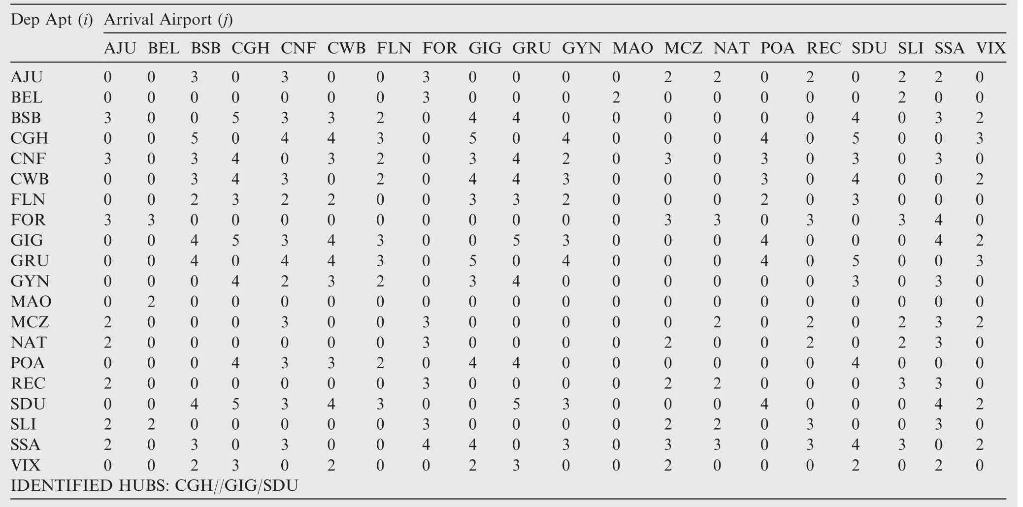
Table B2 Maximum network profit - frequencies per sector (Fleet#2-85 seats).
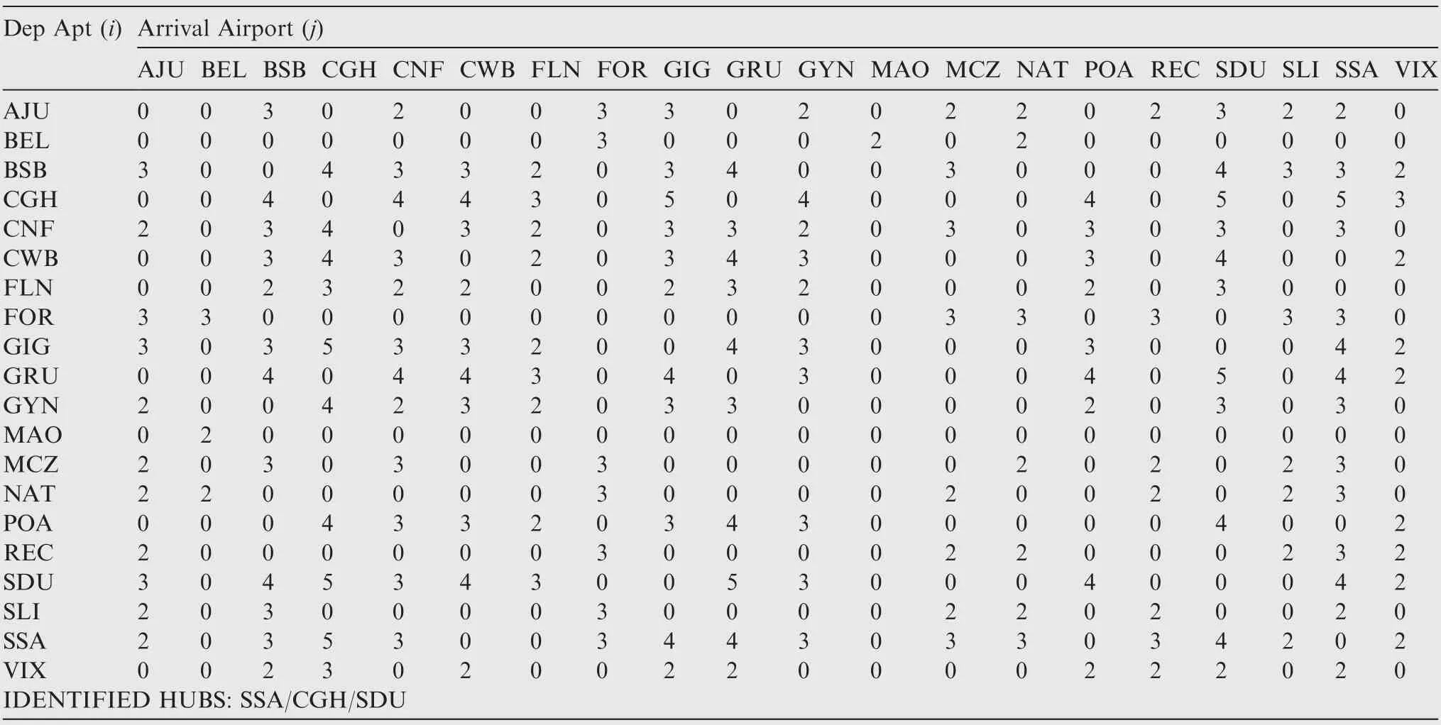
Table B3 Maximum network profit - frequencies per sector (Fleet#3-91 seats).
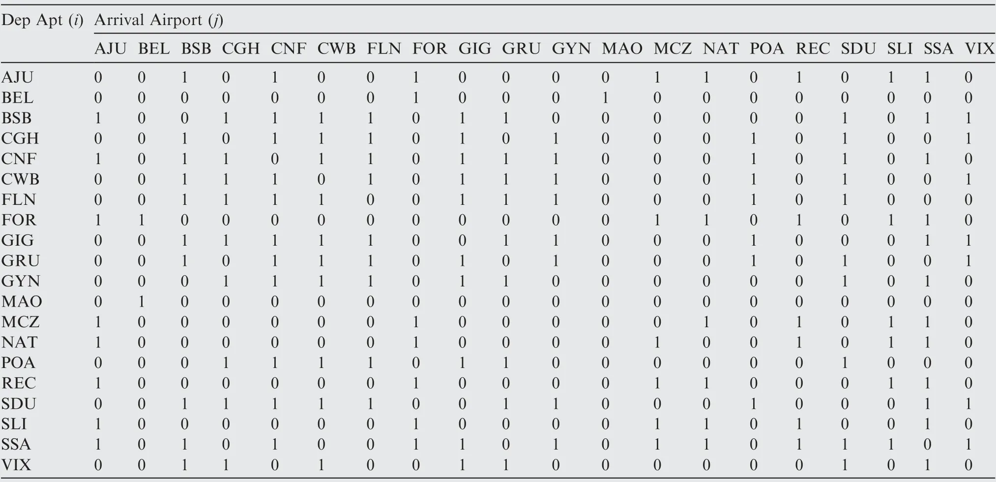
Table B4 Maximum network profit - common connections of 3 fleets.
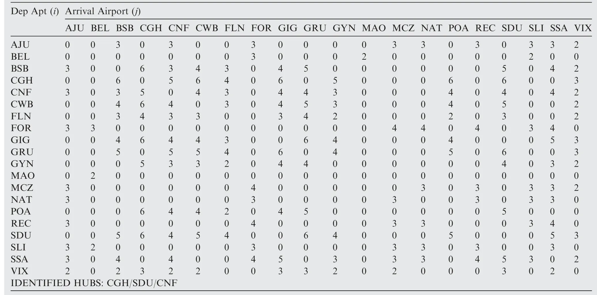
Table B5 Minimum network DOC - frequencies per sector (Fleet#1-70 seats).
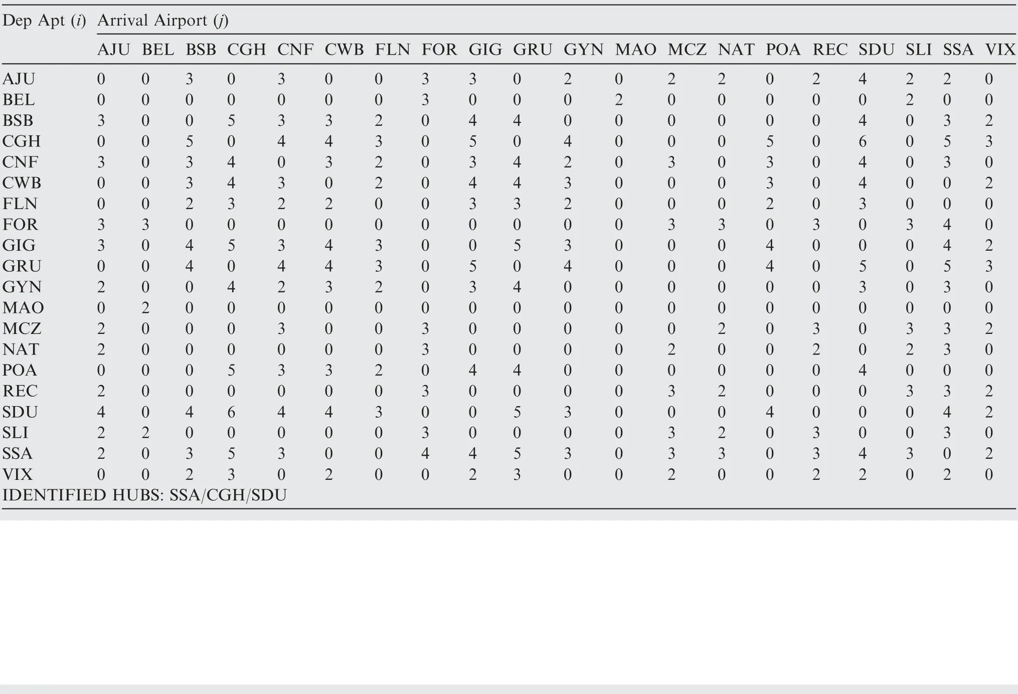
Table B6 Minimum network DOC - Frequencies per sector (Fleet #2-84 seats).
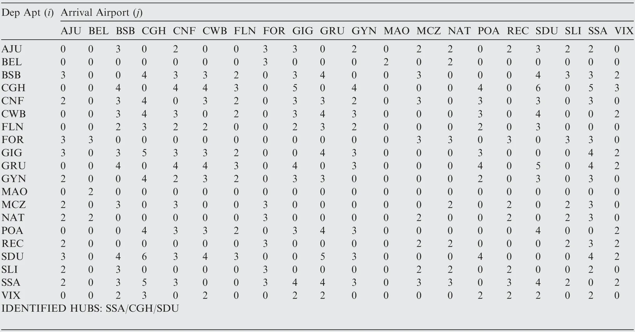
Table B7 Minimum network DOC - frequencies per sector (Fleet #3-91 seats).

Table B8 Minimum Network DOC - Common connections of 3 fleets.
Appendix C. Final optimization results
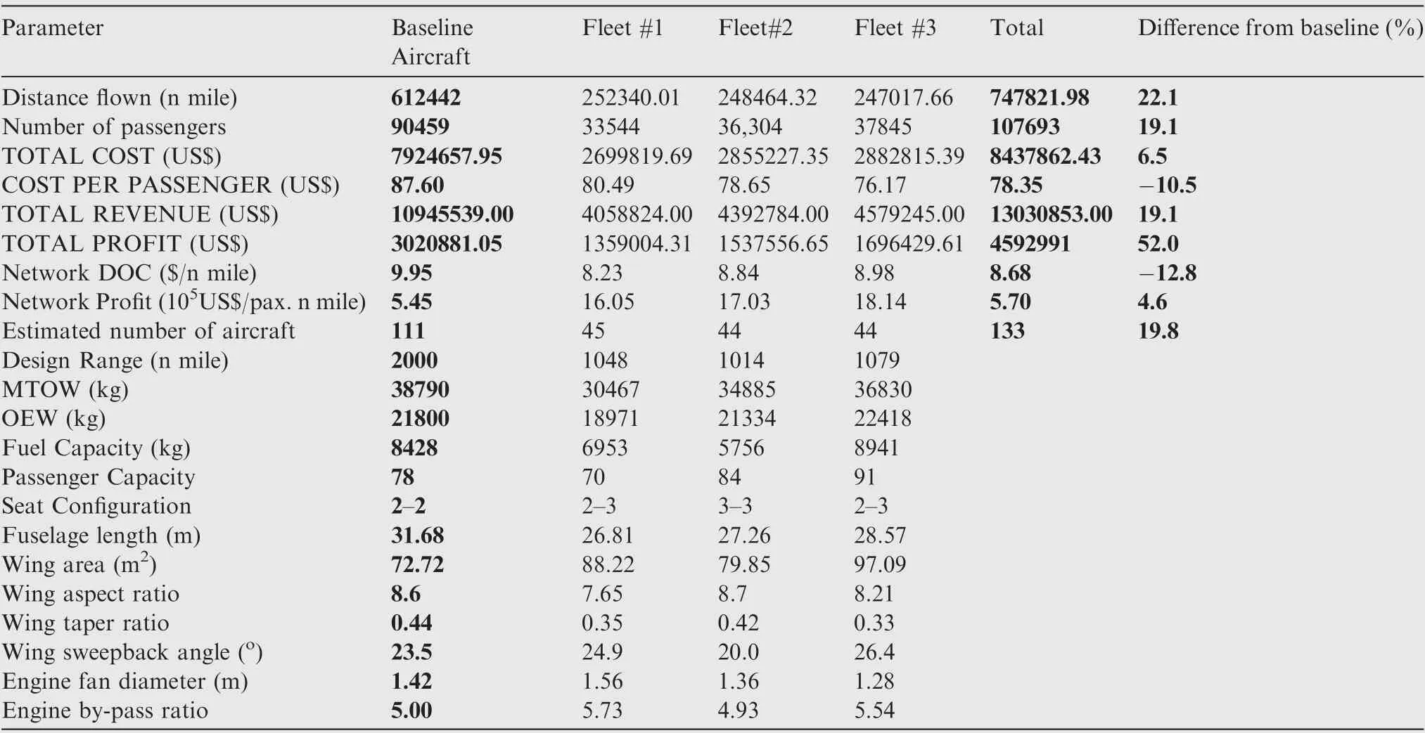
Table C1 Results for minimum network DOC scenario.
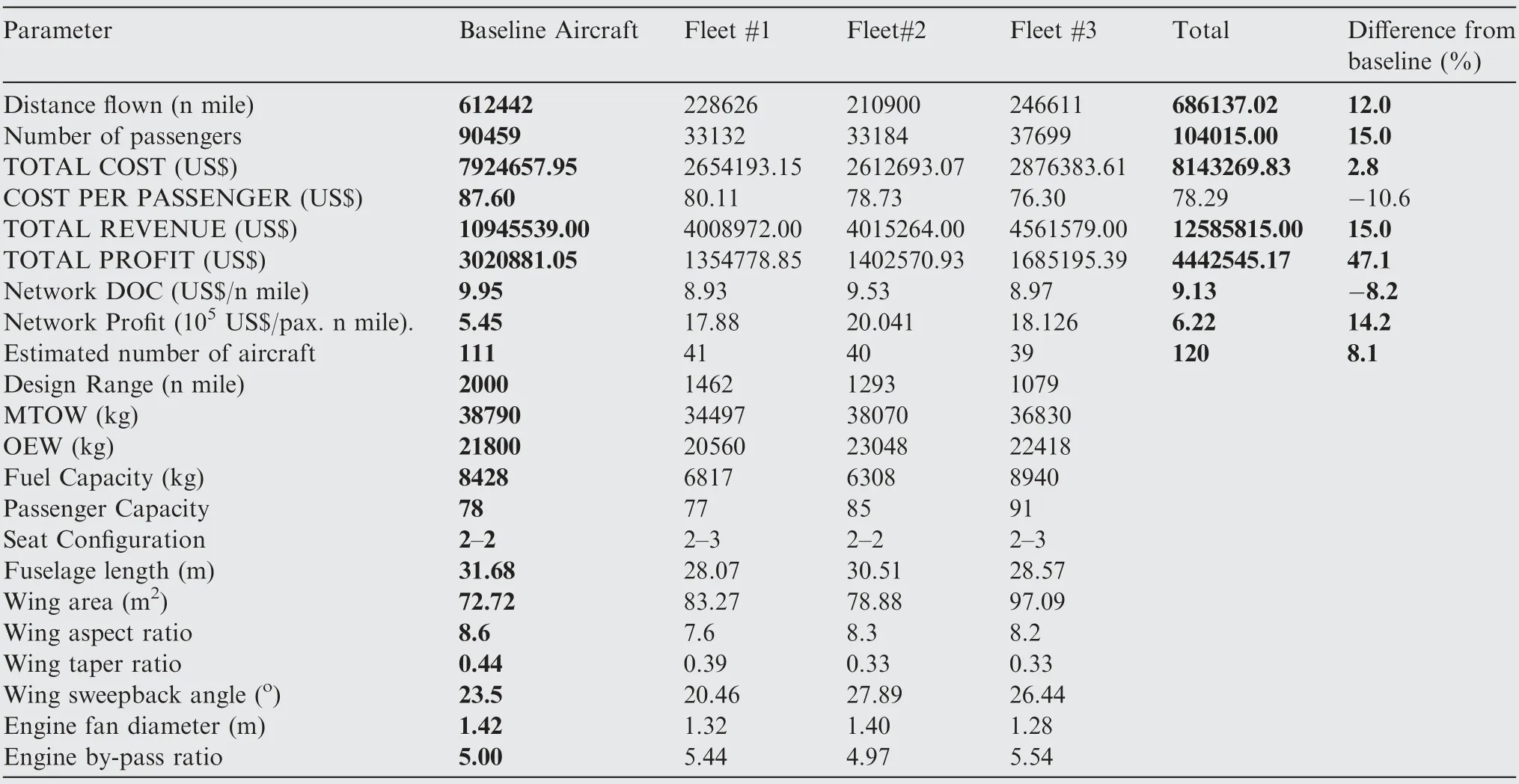
Table C2 Results for maximum network profit scenario.
 CHINESE JOURNAL OF AERONAUTICS2020年2期
- CHINESE JOURNAL OF AERONAUTICS的其它文章
- Delaying stall of morphing wing by periodic trailing-edge deflection
- Optimization and verification of free flight separation similarity law in high-speed wind tunnel
- Non-intrusive reduced-order model for predicting transonic flow with varying geometries
- Consideration on aircraft tire spray when running on wet runways
- Aeroelastic simulation of the first 1.5-stage aeroengine fan at rotating stall
- Experimental study on NOx emission correlation of fuel staged combustion in a LPP combustor at high pressure based on NO-chemiluminescence
