Multiscale topology optimization using feature-driven method
Zhao XU, Weihong ZHANG, Ying ZHOU, Jihong ZHU
State IJR Center of Aerospace Design and Additive Manufacturing, Northwestern Polytechnical University, Xi’an 710072, China
KEYWORDS Feature-driven method;Level set function;Multiscale design;Topology optimization;XFEM
Abstract This paper presents a multiscale design method for simultaneous topology optimization of both macrostructures and microstructures.Geometric features are extended as design primitives at both macro and micro scales and represented by Level Set Functions(LSFs).Parameters related to the locations, sizes, and orientations of macro and micro features are considered as design variables and optimized simultaneously.In the overlapping areas of different macro features,embedded microstructures are optimally figured out as the solution of the corresponding sub-optimization problem.In this study,the eXtended Finite Element Method(XFEM)is implemented for structural and sensitivity analyses with respect to design variables. This method has the advantage of using a fixed grid independent of the topology optimization process. The homogenization procedure is applied to calculate the effective properties of considered microstructures in each macro feature.Numerical examples are presented to illustrate the effectiveness of the proposed method. Results depict that the multiscale design cannot obviously improve structural stiffness compared with a solid-material design under the linear elastic condition.
1. Introduction
Nowadays,topology optimization is recognized as an effective design approach.It has been intensively studied and applied in the past decades.1Different methods have been developed and can be classified according to the nature of involved design variables.The Density-Based Method(DBM)2is mainly based on the Solid Isotropic Material with Penalty (SIMP) and Rational Approximation of Material Properties (RAMP)scheme by which design variables are associated with elemental pseudo-densities attached to a finite element model.The Level Set Method (LSM)3originates from a mathematically mature boundary tracking model,in which shape and topology evolutions are achieved through evolving structural boundary velocities. In recent years, constructive features have been adopted as design primitives owing to their strong CAD-oriented representation with a relatively small number of design variables.4-7
Although topology optimization methods were initially devised for layout design of macrostructures,8they were rapidly extended to material microstructures9-18and even the multiscale optimization with the help of implemented homogenization procedure.19-21In this sense,the DBM was the most popular in simultaneous optimization of macrostructures and microstructures.22,23It was extended to scale-related optimization of layered structures filled with cellular materials.24Microstructure orientations were also studied as design variables.25,26Besides, material non-linearity and elasto-dynamic behaviors were considered in multiscale optimization.27,28Bidirectional Evolutionary Structural Optimization (BESO)was applied as an alternative of the DBM.29In the context of laminate composites, multiscale optimization was carried out by interpreting the design of fiber orientations as a Discrete Material Optimization (DMO) problem for the avoidance of the local optimum.30The so-called Shape Function with Penalization (SFP) scheme was introduced to reduce the number of design variables.31This technique was generalized as a bi-value coding parameterization method for design of structural topology and fiber orientations.32Recently, a great trend is to integrate multiscale topology optimization with additive manufacturing.33The LSM has its advantage of obtaining smooth structural boundaries in simultaneous design.34A decomposition strategy was proposed to employ the LSM in both macro and micro designs.35In fact, the DBM and the LSM could also be combined in simultaneous design.36
The Feature-Driven Method(FDM)can be regarded as an extension of feature modeling techniques widely used in the CAD domain into topology optimization. It is also a kind of CAD-oriented LSM. Features can be solids and voids with fixed or changing shapes depending upon a designer’s intents.37-39Super-ellipses and Closed B-Splines (CBS) are often selected as features owing to the simplicity and small number of design variables.40-42Meanwhile,the FDM is more adapted to 3D printing for easy imposition of manufacturing constraints such as overhang and connectivity constraints.43Similarly, specified geometrical shapes are embedded into the design domain by LSFs with the domain integral form of non-overlapping constraints.44Later, this method was used for topology optimization with embedded piezoelectric actuators.45In addition, flexible voids were integrated in densitybased topology optimization.46
Fig. 1 illustrates the DBM for multiscale optimization.Although microstructures were freely designed,22,29identical microstructures were generated in each local region. This implies that it is reasonable to assume identical microstructures in each macro feature in our design. From the engineering viewpoint, each macro feature of identical microstructures can be regarded as a modular substructure for construction of the whole macro structure. This assumption makes it possible to reduce the number of microstructure design variables and the data size of the whole model. In an extreme case, identical microstructures could even be imposed over the whole structure.21
In this study,a macro design model and a micro Representative Volume Element (RVE) are constructed in terms of macro and micro features. Specifically, each macro feature is assumed to consist of identical microstructures that are optimized in their corresponding RVEs.The homogenization procedure is implemented in its energy-based scheme to calculate the effective elasticity matrix of the microstructure. The XFEM is employed to ensure the computing accuracy of the multiscale structure with a fixed grid.47,48It is shown that the feature-driven topology optimization method only requires a moderate number of design variables at both scales compared to those of the DBM and the LSM. However, one underlying problem is how to carry out the microstructure design in the overlapping areas of macro features. To tradeoff the microstructures of overlapping macro features, the optimality criterion is proposed to select a microstructure from available candidates by solving the corresponding suboptimization problem.
The remainder of this paper is organized as follows:in Section 2, the feature-driven method is briefly presented together with the formulation of multiscale topology optimization; in Section 3, a multiscale optimization procedure including the optimality criterion is developed;the sensitivity analysis is stated in Section 4; several numerical examples are illustrated in Section 5; conclusions are given in Section 6.
2. Formulation of the feature-driven multiscale topology optimization problem
2.1. Multiscale modelling of a structure with features using Boolean operations
The basic notion of the feature-driven method for multiscale topology optimization is illustrated in Fig. 2. Without loss of generality, suppose that a macrostructure is composed of designable (in gray) and non-designable (in red) macro features also called components. Here, a designable feature means that it can rotate, translate, change the shape, shrink to a negligible size, and even overlap with other features. Therefore, its location, orientation, size, and shape parameters can be chosen as design variables. A non-designable feature means that it can only move and rotate, but cannot overlap in order to preserve the shape and engineering functionality.It can represent a mechanical part, device, electronic component, modular substructure, and even a shaped functional hole. Meanwhile, each macro feature can have its proper microstructure designed with multiple micro features at the microscale.
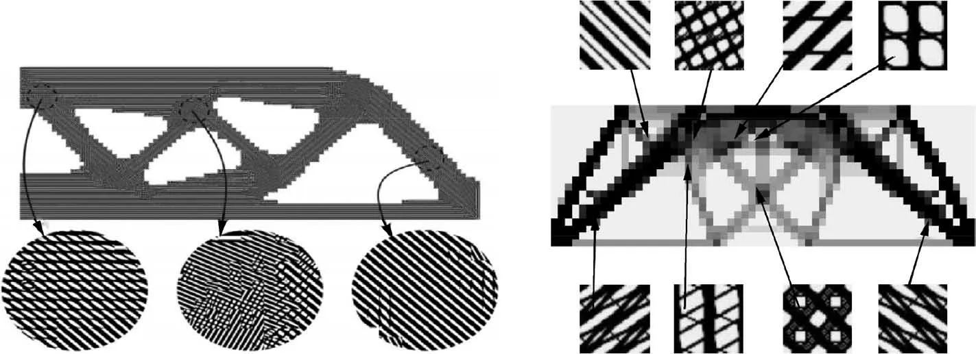
Fig. 1 Multiscale topology optimization with density-based method.
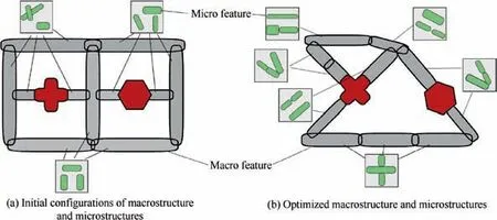
Fig. 2 Illustration of a multiscale topology optimization structure.
Mathematically,any geometrical feature can be represented by an LSF whatever the complexity is. The material property can simply be attributed according to the sign of the LSF. In contrast to parametric function representations, e.g., Bezier and B-spline,manipulations of features can be rigorously realized by means of Boolean operations of the LSFs.Figs.3 and 4 depict the LSFs of a super-elliptical feature and two polygonal features, respectively.
In this work, designable solid features are represented by super-ellipses at both scales. Let (x, y) and () denote the positions of an arbitrary point in the global and local coordinate systems,respectively.Parameters xc,yc,ac,wc,and lcrepresenting the central coordinates,angle,width,and axis length of the super-ellipse are considered as design variables. The exponent n usually takes the value of n=5. The LSF is expressed as

The LSF of the whole structure can then be achieved by means of Boolean operations. These operations are typically in the forms of R-function,KS-function,and P-norm function.For example,assume that φ1and φ2are the LSFs of two independent features. Their R-conjunction and R-disjunction correspond to

To clearly distinguish the macro- and microscale in the sequel, capital letters will denote the macroscale. Let M be the number of macro features defining a macrostructure. A solid feature i then holds the following property:

For the whole macrostructure, the overall LSF, Φ, related to the R-conjunction is calculated as

Detailed discussions about the LSF representations of complicated features can be found in Reference.49
2.2. Feature-driven multiscale topology optimization
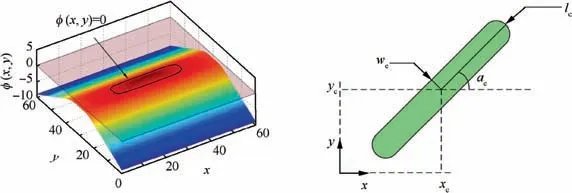
Fig. 3 Level set function of a super-elliptical feature and its design variables.

Fig. 4 Level set functions of polygonal features.


Here, the strain energy (also the compliance under a static load)of the macrostructure is the objective function.V denotes the solid volume of the macrostructure. videnotes the solid volume of the microstructure in one RVE related to the ith macro feature.Q and q refer to the prescribed volume fractions at the macro- and microscale, respectively. V-and v-denote the volume of the macro design domain and that of the micro RVE, respectively. By default, v-=1. H denotes the Heaviside function. K, U, and F represent the global stiffness matrix,nodal displacement vector, and nodal force vector of the macrostructure, respectively.
2.3. Microstructure optimization in overlapping areas of macro features
Fig.5 shows the overlapping areas of three macro features.To optimally determine the embedded microstructure in each overlapping area,a sub-optimization problem is defined correspondingly and then solved. The most suitable microstructure is obtained in the sense of minimizing the strain energy of the macrostructure.To do this,the elasticity matrices of all candidate microstructures related to the macro features are weighted as the elastic property in a considered overlapping area, and the weighting coefficients are used as design variables.
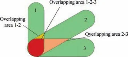
Fig. 5 Illustration of overlapping areas of macro features.
To make things clear,assume that the kth overlapping area is formed by local overlapping of N macro features.w1(k),w2(k),..., wN(k)refer to the corresponding weight coefficients. The resulting effective elasticity matrix of the kth overlapping area can thus be formulated as

where p represents the penalty coefficient normally set to p=3 as in the SIMP scheme. D1H, ..., DNHdenote the effective elasticity matrices of the microstructures related to N macro features. Hence, the sub-optimization problem related to the kth overlapping area is stated as

Sensitivity analysis can be derived as

with

where B denotes the displacement-strain matrix.Generally,the above problem related to Eq.(7)could be solved by means of mathematical programming. Nevertheless, considering the special form,a more efficient way is to use the Optimality Criteria (OC) discussed in Reference.8The solution scheme is

where δ is the move limit, and b=0.5 is the damping coefficient. β is calculated as

Here, the Lagrangian multiplier λ is determined by the bisection algorithm to satisfy the constraint. The iteration of the above sub-problem is stopped for a solution when all weighting coefficients take the 0/1 values.
3. Multiscale optimization procedure
3.1. Multiscale structure analysis using the XFEM
In this paper, the XFEM is employed in both macro- and microscale analysis. When an element is crossed by a material interface, it is divided into sub-triangles according to the Partition of Unity Method (PUM).50As shown in Fig. 6, the element stiffness then corresponds to the summed contributions of all solid sub-triangles.
To do this, the coordinates of intersection points 5 and 6 are firstly determined. Suppose that the material interface is described by the LSF φ (x,y). One simple way is to perform interpolations based on the LSF values at nodes.For example,the coordinates of node 5 in the first case of Fig. 6 are computed as follows:

Unfortunately, the above solution strongly depends upon the LSF values at related nodes. Intersection node 5 might be poorly interpolated due to the non-uniformity property of the LSF φ(x,y), as illustrated in Fig.7(a). Therefore, the normalized form of the Signed Distance Function(SDF)is used to overcome this difficulty5as follows:

Fig.7(b)illustrates that the LSFhas a local uniformity of the iso-value contours near the material boundary for correct determination of node 5. With this idea in mind, all basic features presented in Section 2 are normalized into the form of
Consider now material-material and material-void interfaces. According to Reference45interpolation schemes of the XFEM are different.In a material-material case,displacement interpolation is enriched to reflect the stress discontinuity along the material interface. For a quadrilateral element, the expression is
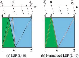
Fig. 7 Illustrations of LSF and normalized LSF.

Here, uirepresents the displacement of regular node i, and ajdenotes the enrichment DOF. Niand Njare traditional Lagrangian and enrichment shape functions that hold the same form in this work.F(x,y)is the enrichment function that reflects the stress discontinuity. It can be a function of any form, but different choices may lead to different results.Moe¨s et al proposed the following F(x,y)with a good rate of convergence and accuracy51:

where φ-iis the value of the LSF at each node of the element.
In a material-void case, as the nodal displacement in the void part is directly set to zero,the displacement interpolation is expressed as

By using Gauss quadrature, the element stiffness matrix at the macroscale can be calculated as


Fig. 6 Illustrations of the PUM in different cases of material interfaces.
where Dgpis the elasticity matrix at the Gauss point, Bmacrodenotes the displacement-strain matrix at the macroscale,and J denotes the Jacobian matrix.
3.2. Homogenization of microscale material properties
Microstructure optimization of an RVE is also modeled by the FDM that produces a relatively smaller number of design variables than that of the DBM. By means of the energy-based homogenization method,52the effective elasticity matrix DHis calculated to relate both scales.In a 2D case,DHis expressed as

where term Qijis the sum of element mutual energies over the RVE at the microscale.To calculate Qij,the RVE is discretized into n elements.Meanwhile,three load cases A(1),A(2),and A(3)are applied,and Periodic Boundary Conditions(PBCs)are imposed to the RVE. Fig. 8 shows the nodal DOFs that are divided into four groups U1-U4according to their locations.The equilibrium equation with respect to U1-U4can be expressed as


where α is a small coefficient used to represent the void,and D0is the elasticity matrix of the base material.
Based on the PBCs, Eq. (19) can be expressed as

Its solution is used to determine Qijas follows:

Fig.9 illustrates a mesh of 25×25 elements used for a single microstructure cell. The density-based optimization will inevitably lead to fuzzy design results and bring difficulties to the subsequent design and manufacturing.In contrast,with the same background mesh,feature-driven design can produce a clear microstructure pattern.
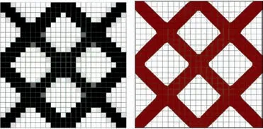
Fig. 9 Microstructure representation using SIMP method (left)and micro features (right).
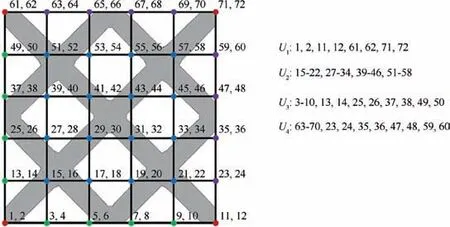
Fig. 8 RVE discretized into 5×5 elements.
3.3. Numerical implementation
The multiscale optimization procedure can be realized as follows. Firstly, 5 M macro design variables and 5Mn micro design variables are defined to model the macrostructure and the involved microstructures. The XFEM is applied for structural analysis at the macroscale and for the calculation of the effective elasticity matrix DHof the microstructure at the microscale. Sensitivity analyses are carried out with respect to macro and microscale design variables, respectively. Secondly, concurrent optimization is carried out. At each optimization step, a sub-optimization problem is solved by means of the OC method to find out the microstructure in each overlapping area. The flowchart is illustrated in Fig. 10.
4. Multiscale sensitivity analyses of macro and microstructures
4.1. Sensitivity analysis with respect to macroscale design variables
Suppose that the external force F is irrelevant of the design variables. The sensitivity of the macrostructural compliance corresponds to

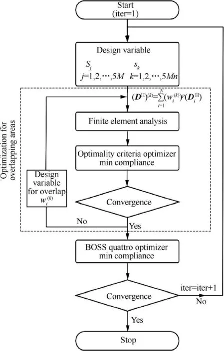
Fig. 10 Flowchart of multiscale topology optimization.
Here, the global stiffness matrix is the assembly of element stiffness matrices at the macroscale.Clearly,the key of the sensitivity analysis is to calculate/∂Sj.In view of Eq.(17),it follows that

in which derivatives of Bmacroand det J are expressed as

4.2. Sensitivity analysis with respect to microscale design variables
Similarly, sensitivities with respect to microscale design variables are expressed as with


Assume (xgp,ygp)∈feature i. It then follows

in which each term is calculated as

and the sensitivity of the element stiffness matrix in an RVE is computed as

5. Numerical examples
5.1. Cantilever beam
A cantilever beam of size 80×40 is clamped at the left end and loaded by a concentrated force F=1 at the right end, as shown in Fig. 11.Suppose that the macrostructure is modeled by M=16 super-elliptical features with the number of macro design variables 5 M=80.
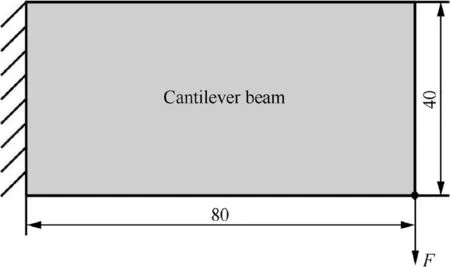
Fig. 11 Cantilever beam with a concentrated force.
Meanwhile,the microstructure involved in each macro feature is modeled by n=8 super-elliptical features so that the number of micro design variables is 5Mn=640. The volume fractions of macro and microstructures are all set to Q=q=50% in Eq. (5). The base material is homogeneous with a Young’s modulus of E=10 and a Poisson’s ratio of ν=0.3. Fig. 12 shows evolutions of macro and microstructures after simultaneous optimization. Some intermediate results are also illustrated. The layout of macro features and involved microstructures is optimized to minimize the structural compliance. Fig. 13(a) shows that the iteration has a stable convergence. Fig. 13(b) shows that the volume fraction constraints are satisfied and attain the upper bound at the microscale.
As a microstructure has an infinitesimal size theoretically,any scaling and translation of a microstructure does not influence the effective properties. Fig. 14(a) shows the connections of microstructures in different overlapping areas to transfer load after proper translation and scaling operations. In fact,the proposed nested optimization framework is able to match the microstructures in different locations to minimize the structural compliance.The evolution histories of weight coefficients of connection areas in sub-optimization are depicted in Fig. 14(b). The weight coefficients attain 0/1 solution in a few iteration steps to ensure an optimal micro design.
5.2. MBB beam
Due to the structural symmetry, only half of the structure is studied in Fig. 15. It is loaded by a concentrated force F=1 at the left up corner. The half beam has a design domain of 60×20 and is discretized with 90×30 quadrilateral elements.The base material has a Young’s modulus of E=10 and a Poisson’s ratio of ν=0.3.
To investigate the relationship between the structural response and volume fraction constraints, a series of experiments is implemented with different combinations of micro and macro volume fractions. A total material usage of 36%is imposed, and optimized designs with different volume fractions are illustrated in Fig. 16. It is found that the structure with a solid microscale volume produces the minimum structural compliance.When the porosity ratio raises,the structural compliance rises correspondingly. This phenomenon implies that the microstructure stiffness is weaker than those of solid structures with the same material usage in this case.
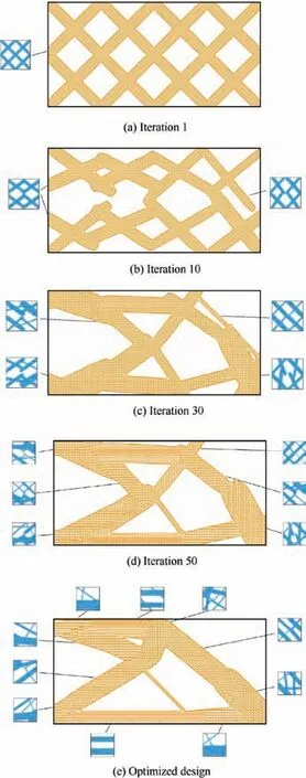
Fig. 12 Evolutions of macrostructures and microstructures of cantilever beam.
The compliances and numbers of design variables of the proposed two-scale method and the density-based method are compared in Table 1. The density-based result refers to the work in Ref.29under the same load and constraints are illustrated in Fig. 17.
The proposed feature-driven method produces a similar compliance value using a smaller number of design variables than that in the density-based method. This characteristic can bring convenience on the memory usage and data transfer process.
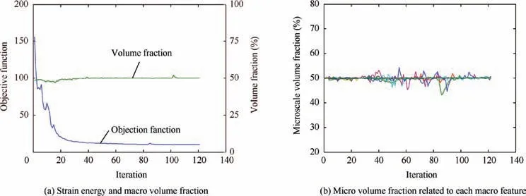
Fig. 13 Convergence histories for cantilever beam.
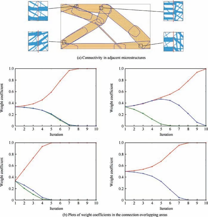
Fig. 14 Connectivity check for cantilever beam.
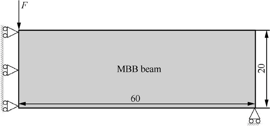
Fig.15 Half of an MBB beam loaded by a concentrated force at the center of upper side.
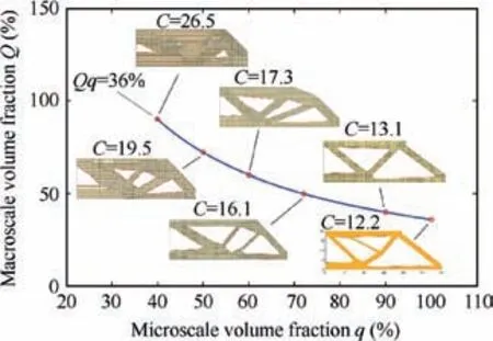
Fig.16 Optimized design of an MBB beam with different macro and micro volume constraints.
5.3. Bridge structure
A bridge structure with a size of 64×20 is fixed at two bottom corners as shown in Fig. 18.A uniform pressure of p=100 is loaded at the top.In order to ensure a pathway of force,a nondesignable area with a width of d=1 is defined at the top.The Young’s modulus and Poisson’s ratio of the base material are E=1×10⁵and ν=0.3, respectively.
To fully investigate the potential of microstructures, the volume constraints on individual features are replaced by a total volume constraint on the whole material usage. Therefore,the microstructures are free to transfer between pure solid design and void design. The structure is modeled by M=20 macro features and n=8 micro features. The total material usage is limited under Qq=50%.The initial and final designs are depicted in Figs. 19 and 20, respectively. Meanwhile, theconvergence histories of the objective function and volume constraints are shown in Fig. 21.

Table 1 Compliance and number of design variables in multiscale optimization.
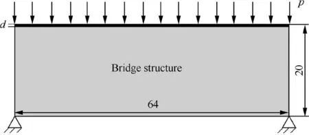
Fig. 18 Bridge structure under a uniform pressure.

Fig. 19 Initial design of bridge structure.
In addition, multiscale results are compared with one-scale ones with volume fractions of 40% and 50% (shown in Table 2). The multiscale results are found to have about 10% improvement on the objective function. Some truss-like porous microstructures are generated to provide support in a relatively large zone. In this sense, the multiscale design possesses a larger design space with more freedom,and thus leads to a better result than a traditional solid-void Michell structure. The same conclusion was also drawn out by Sigmund et al.53
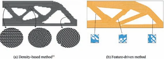
Fig. 17 Comparison of results for MBB beam between different methods.

Fig. 20 Optimized design of bridge structure.
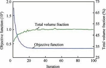
Fig. 21 Convergence histories of objective function and volume fraction.
5.4. Two-hole structure with a complicated outer boundary
Inspired from an aircraft structure with a complicated shape shown in Fig. 22, a two-scale optimization model is studied in Fig.23.Suppose that the structure is loaded by a uniformly distributed force of q=100 N/cm on the top and a moment of two identical forces F=1 kN on both sides. The bottom of the structure is fixed. Because of its symmetry, only a half is considered. Young’s modulus and Poisson’s ratio of the base material are E=100 GPa and ν=0.3, respectively. The whole design domain is discretized by 62×74 elements.
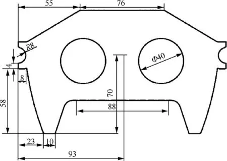
Fig. 22 An engineering structure with two holes (unit: cm).
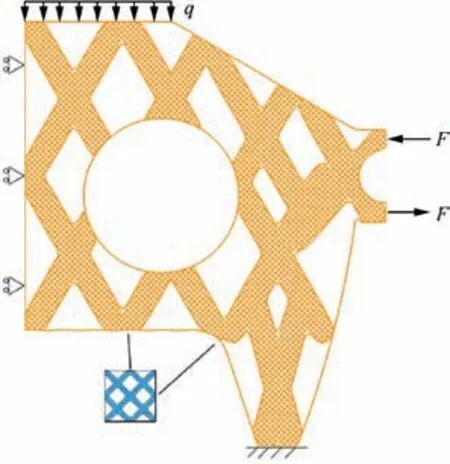
Fig. 23 Initial two-scale optimization model and boundary conditions.
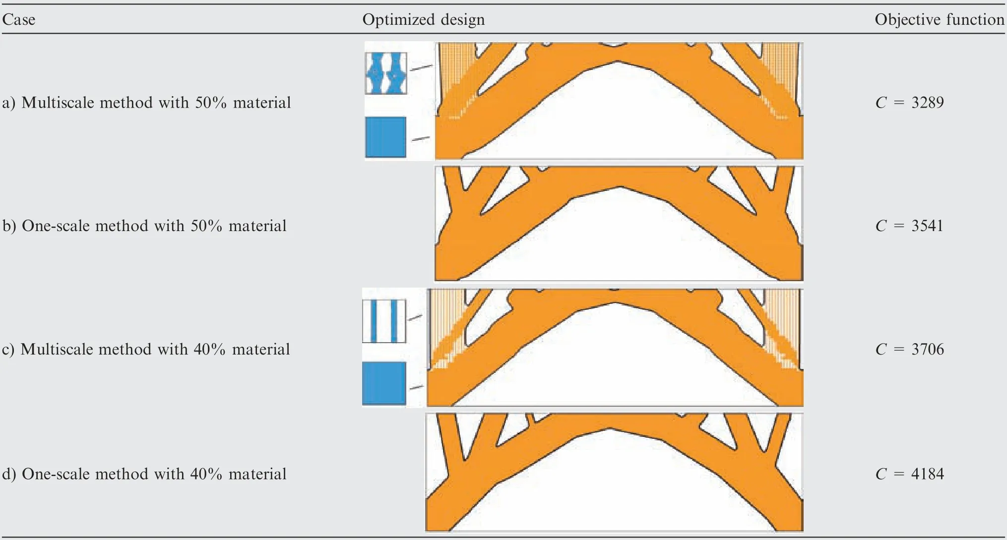
Table 2 Optimized design and the objective function values.
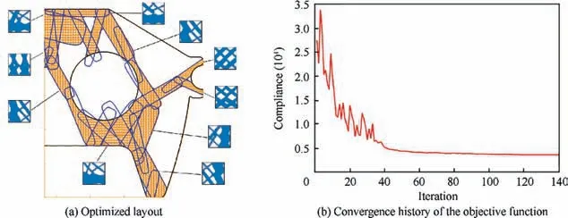
Fig. 24 Optimized result of two-hole structure.
The volume fractions at macro and micro scales are Q=50% and q=60%, respectively. The optimized design and convergence history are shown in Fig. 24.
6. Conclusions
In the present paper,a feature-driven method is developed for multiscale topology optimization.Both macro and microstructures are described by the LSFs of multiple features,and topological changes are achieved by moving and changing the features. The problem of minimizing the strain energy of the macrostructure is considered within the framework of the FDM. The number of design variables can be reduced significantly compared to that of the DBM. It is found that smooth boundaries of the macro and microstructures are obtained owing to the feature definition. Optimized microstructures are different depending upon locations of the optimized macrostructures. Especially, microstructures are optimally selected in the overlapping areas of macro features. Translation and scaling operations are used to check microstructure connections without influencing their effective properties. In fact, the proposed nested optimization framework is able to match the microstructures at different locations for their connections to minimize the structural compliance. Results indicate that these microstructures are well connected to suit the loading condition. Compared to a solid-material design, no obvious improvement of structural stiffness can be obtained through a multiscale design.
Acknowledgements
This work is supported by National Key Research and Development Program of China (No. 2017YFB1102800) and National Natural Science Foundation of China (Nos.11432011, 11620101002, 11722219).
 CHINESE JOURNAL OF AERONAUTICS2020年2期
- CHINESE JOURNAL OF AERONAUTICS的其它文章
- Delaying stall of morphing wing by periodic trailing-edge deflection
- Optimization and verification of free flight separation similarity law in high-speed wind tunnel
- Non-intrusive reduced-order model for predicting transonic flow with varying geometries
- Consideration on aircraft tire spray when running on wet runways
- Aeroelastic simulation of the first 1.5-stage aeroengine fan at rotating stall
- Experimental study on NOx emission correlation of fuel staged combustion in a LPP combustor at high pressure based on NO-chemiluminescence
