Experimental investigations of the spray structure and interactions between sectors of a double-swirl low-emission combustor
Xiongjie FAN, Cunxi LIU,*, Gang XU, Chi ZHANG, Jianhen WANG,Yuzhen LIN
a School of Engineering Science, University of Chinese Academy of Sciences, Beijing 100190, China
b Key Laboratory of Light-duty Gas-turbine, Institute of Engineering Thermophysics, Chinese Academy of Sciences, Beijing 100190,China
c National Key Laboratory of Science and Technology on Aero-Engine Aero-thermodynamics, School of Energy and Power Engineering, Beihang University, Beijing 100083, China
KEYWORDS Combustor;Fuel-air ratio;PIV;PLIF;Pressure drop;Swirl intensity
Abstract In this paper, the spray characteristics of a double-swirl low-emission combustor are analyzed by using Particle Imaging Velocimetry (PIV) and Planar Laser Induced Fluorescence(PLIF) technologies in an optical three-sector combustor test rig. Interactions between sectors and the influence of main stage swirl intensity on spray structure are explained.The results illustrate that the swirl intensity has great effect on the flow field and spray structure.The spray cone angle is bigger when the swirl number is 0.7,0.9 than that when the swirl number is 0.5.The fuel distribution zone is larger and the distribution is more uniform when the swirl number is 0.5. The fuel concentration in the center area of the center plane of side sector(Plane 5)is larger than that of the center plane of middle sector(Plane 1).The spray cone angle in Plane 5 is larger than that in Plane 1.The width of spray cone becomes larger with the increase of Fuel-Air Ratio (FAR), whereas the spray cone angle under different fuel-air ratios are absolutely the same. The results of the mechanism of spray organization in this study can be used to support the design of new low-emission combustor.
1. Introduction
There is an urgent need of improving combustion efficiency and decreasing emission pollution with the increase of stringent regulations on pollutant emissions.1,2Nowadays,in order to improve the fuel atomization performance and reduce pollution, fuel-staged partially premixed combustors are applied.The combustor consists of pilot stage and main stage. The pilot stage adopts diffusion combustion to improve the ignition and the main stage adopts partially premixed combustion to improve combustion efficiency,avoid hot streak and reduce pollution emission. Air-blast nozzle is commonly used in lowemission combustor, in which the flow field organization and the spray organization determine the combustion efficiency and temperature distribution.
Innovative designs for coping with operability and future regulations on pollution emissions have been done by a lot of researchers. Swirl cup combustors based on swirlstabilized combustion have been applied extensively to modern aero-engine combustors because of the excellent combustion performance.3Hence, many researchers have carried out a lot of studies on the flow field, spray and combustion performance of swirl cup combustors. McDonell et al. studied the effects of geometry parameters on the flow field and spray,including flare geometry, confinement, and swirl angle etc.4-7Ateshkadi et al.8studied the effect of swirl vane angle, swirl sense and venturi on LBO (Lean Blow-Out) performance, a new LBO correlation model accounting for heterogeneous reaction and geometry of mixer component is developed.Ateshkadi5and Mongia9et al. studied the downstream spray field of a swirl cup combustor using PLIF technology, the results showed that venturi can control the area of fuel distribution, and form a typical cone distribution. Hadef and Lenze10researched the effect of co- and counter-swirl on the droplet characteristics. The results indicated that the atomization was finer and more spatially dispersed in the counter-swirl configuration. This advantage leads to easier ignition, a wider burning range,lower pollutant emissions and high combustion efficiency.Based on these studies,the spray structure,the flow field structure, the interactions between swirling air streams,the main factors determining the spray and regularity have been given for the swirl cup combustor.
Recently,a lot of studies on the flow field and spray performance of the fuel-staged low-emission combustor have been carried out. Li and Gutmark11used the PIV technology to measure the flow field of a three-swirl combustor under cold condition, and studied how the air amount, the swirler structure and the length of the mixing tube influence the flow field.Seol et al.12studied the influence of the blade rotation direction on the flow field and spray field of a double-radial-swirl combustor. Lilley13summarized the recirculation characteristics of cold flow and hot flow,and found that heat release from combustion process has a major impact on the flow field.Elkady14, Li15and Cai16from University of Cincinnati conducted a series of optical measurements and numerical simulations on multi-stage swirler,and studied how the swirl number influence the flow field and spray field. Lin et al.17-19studied the influence of swirler rotation and step height on the flow field and spray field of fuel-stage combustor. Zhang et al.20studied the Sauter Mean Diameter (SMD) and uniformity index (N) of a counter swirler, the results showed that with the increase of pressure drop, the SMD and the N gradually decreased, and the fuel distribution became less uniform. Liu et al.21used the PIV and PLIF technology to study the flow field and spray field of a three-swirl combustor under nonreacting conditions, and studied how the venturi angle and main swirl angle influence the flow field and spray field. The results showed that the recirculating air streams in main stage will affect the trajectory of pilot air steams and location of vortex in pilot recirculation zone, and the main swirl angle has a great impact on droplet spatial distribution. Under the same overall pressure loss, the spray cone angle increases with venturi angle.The above studies are mainly based on single-sector combustor,and the flow field and spray organization processes of single-sector combustor have been basically explained.However, for the fuel-staged low-emission combustor, more than 60% of the total combustor air goes through the sector,which induces the enhanced interactions between sectors.The flow field and spray characteristics are affected by the interactions between sectors,22but now the interaction process is still unclear.
In this paper, a three-sector optical visible combustor is designed for a type of double-swirl low-emission combustor(BUAA TeLESS).There are three different main stage models with different swirl numbers (M=0.5, 0.7, 0.9), the main stage swirl intensity changes as the angle of main stage blades change,while the opening area is keeping constant.In order to study the effects of main stage swirl intensity on the spray structure and the interactions between sectors, the experimental investigations of the spray structures at various testing planes in the low-emission combustor with different main stage swirl numbers (M=0.5, 0.7, 0.9) have been carried out.
2. Experimental setup
2.1. Model combustor
The optical three-sector combustor test rig is shown in Fig. 1.The combustor has two-stage counter-rotating axial swirlers(Fig. 1(a)). The pilot stage uses a pressure-swirl atomizer for primary atomization.The pilot stage blades are counter clockwise, and the main stage blades are clockwise. The pilot stage is in a swirl cup structure. Part of the fuel impact the venturi wall to form a film, which will be further atomized by the two-stage counter-rotating air at the exit of the swirler. Some small droplets in pilot stage follow the swirl air directly into the main combustion zone. There are three different main stage models with different swirl numbers (M=0.5, 0.7,0.9). The pressure difference (ΔP) is measured between upstream and downstream of the swirler. The relative swirler pressure drop is defined as ΔP/P3(P3is the pressure at the swirler inlet).Quartz glass measurement windows are arranged on the upper side and the right side of the test rig.
Fig. 1(b) shows the measurement planes (Plane 1-Plane 5),the distance between Plane 1 to Plane 5 is 107 mm, the test Plane is 160 mm×140 mm. Plane 1 is the center plane of the middle sector,and Plane 5 is the center plane of the side sector.All planes are uniformly distributed.In the test rig,the x axis is axial direction,the y axis is radial direction.Fig.1(c)shows the combustor test rig.
2.2. Optical setup
The experiment was carried out on the spray/combustion optical diagnostic test bench of the Institute of Engineering Thermophysics, Chinese Academy of Sciences. Under ambient temperature and pressure condition, swirler pressure drop ΔP/P3of 1%, 2%, 3%, 4% and fuel-air ratio of 0.01, 0.02,0.03 were selected in this study for the underground ignition condition.The fuel-air ratio is controlled by the fuel mass rate with a constant air mass rate.Operating conditions are shown in Table 1.
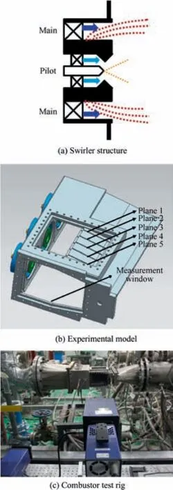
Fig. 1 Model combustor.
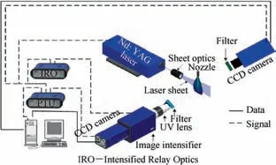
Fig. 2 Optical setup.
The optical setup comprises of a laser system,an image capture and processing system,and a controlling system as shown in Fig. 2. The laser system with sheet optics produces laser pulses having a duration of 8 ns and a thickness of about 1 mm at a repetition rate of 15 Hz. The laser is operated with a 2nd and 4th harmonic generator to produce pulse energy of 300 mJ at 532 nm and 25 mJ at 266 nm respectively.A doubleexcitation scheme with laser wave length of 532 nm and a single-excitation scheme with laser wave length of 266 nm are used in PIV and Fuel-PLIF experiments respectively. The image capture system consists of image intensifier, Charge-Couple Device (CCD) camera, lenses, interference band-pass and long-pass filters. The optical signals were detected with a CCD camera perpendicular to the laser sheets. The camera is a 12-bit CCD with resolution of 1376 pixel×1024 pixel and a framing rate of 10 Hz. In the PIV setup, the CCD camera equips with Nikkor f=25 mm lens and a 532 nm band-pass filter for detecting the 532 nm scattering signal. In the Fuel-PLIF setup, the CCD camera equips with image intensifier,UV Nikkor f=105 mm lens and 266 nm long-pass filters for detecting the LIF signal.RP-3 kerosene has fluorescence signal with spectral band ranging from 270 to 420 nm. The fluorescence is red-shifted with respect to excitation laser wavelength,and the 266 nm long-pass filter can be used to discriminate it from Mie scattered light. The gate width in the kerosene-PLIF experiments was set to 50 ns. The whole system is controlled and synchronized by Personal Computer (PC) via a Programmable Timing Unit(PTU)and the software.An intensified relay optics works together with PTU for setting variable exposure time and intensifier gain.For both the PIV and Fuel-PLIF measurements,the laser sheet is placed through the center of the combustor with the recording CCD camera placed normal to this plane.
The RP-3 kerosene is used both in the spray and combustion experiments. The fuel properties at normal inlet temperature of 293.15 K are density of 783 kg/m3, viscosity of 0.00129 Pa·s and surface tension of 0.024 N/m. For the PIV measurements, the air is seeded with TiO2particles, which are 3-5 μm in diameter and about 4.2 g/cm3in density. There is no fuel droplet in the PIV experiments. The Stokes number expressing the ability of the particle to track the flow is estimated by the ratio of the particle’s characteristic settling time scale (τp) and characteristic time scale (τf) of flow,


Table 1 Operating conditions.

where is ρpthe particle density,dpis the particle diameter,μais the viscosity of air, δ is the relevant length and ΔU is velocity gradient.The highest velocities are on the order of 60 m/s.δ is the smallest resolved length scale, 4.0 mm. Based on Eq. (1),the Stokes number is 0.11, less than 0.5 suggested by Clemens and Mungal.23
3. Results and discussion
3.1.Influence of swirl intensity on spray characteristics of Plane 1 and Plane 5
Figs. 3 and 4 show the spray characteristics and flow field of Plane 1 and Plane 5 under the pressure drop of 3% and Fuel-Air Ratio (FAR) of 0.02, in which the main stage swirl number is 0.5, 0.7, and 0.9. In Fig. 4, Vxis the axial velocity.The schematic diagram of spray cone angle and expansion angle is shown in Fig. 5. The maximum jet velocity is at the expansion angle, and the maximum fuel distribution intensity is at the spray cone angle.
Comparing the flow field structure and the spray structure,it can be found that the flow field plays a decisive role in the forming of spray structure. The spray cone is mainly formed by the high-speed jet (jet velocity and expansion angle) as the droplets are following the swirl air, and there are interactions between flow field and spray field. It can be seen that the flow field mainly contains a high-speed jet with a large expansion angle (42.5°,48°)at the exit of the main stage swirler and a big recirculation zone with two vortices in the center area when the swirl number is 0.7, 0.9, whereas the expansion angle(8.9°)and the recirculation zone are small when the swirl number is 0.5. The above means that the swirl intensity has a great effect on the flow field. From Fig. 3, it can be seen that the spray cone angle (90°, 92°) of swirl number of 0.7, 0.9 is bigger than that (68°) of swirl number of 0.5. The reason may be that when the swirl number is 0.5,the small expansion angle induces large radial velocity loss of droplets. When the swirl number is 0.7/0.9, the expansion angle is large, which induces smaller velocity loss of droplets than that when the swirl number is 0.5.
In addition, it can be seen that the fuel distribution zone is larger and the distribution is more uniform in Plane 5 when the swirl number is 0.5 than those of swirl number 0.7, 0.9,whereas it may be not good to the ignition. The reason is that the small expansion angle induces large radial velocity loss of droplets, which induces more fuel in the recirculation zone.Droplets will follow the large jet velocity to longer axial position, which induces the fuel distribution to be more uniform.
From the results, it can be seen that there are some differences between the spray structure of middle sector and side sector under the same pressure drop and fuel-air ratio when the swirl number is 0.7,0.9,which are mainly induced by the interactions between sectors (as shown in Fig. 6). The flow field in middle sector is affected by the swirling flow of two side sectors, which makes the swirl intensity attenuate greatly and affects the development of the swirl flow in the radial direction,resulting in a small expansion angle of the flow field and a small width of the recirculation zone. The attenuation of side sector swirl intensity is smaller than the middle sector, which results in a large expansion angle and width of the recirculation zone. For example: the fuel concentration in the center area of Plane 5 is larger than that of Plane 1, and the spray cone angle in Plane 5 (98°) is larger than that in Plane 1(90°). The main reason is that the width of the recirculation zone,the jet velocity and the jet expansion angle(52°)in Plane 5 are larger than those (42.5°) in Plane 1 (as shown in Fig. 7).The larger the width of the recirculation zone,more amount of fuel will be in the recirculation zone. The larger the expansion angle is, the larger the spray cone angle is.

Fig. 3 Spray characteristics of Plane 1 and Plane 5 under pressure drop of 3% and FAR of 0.02.
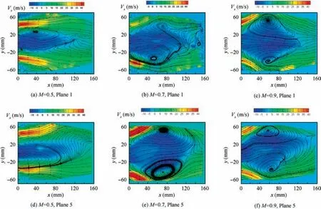
Fig. 4 Flow field characteristics of Plane 1 and Plane 5 under pressure drop of 3% and FAR of 0.02.
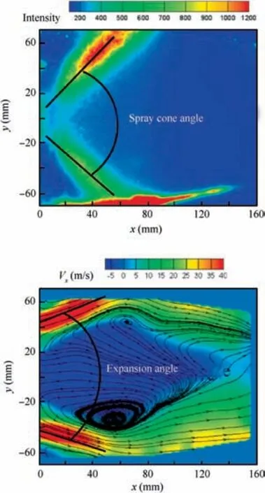
Fig. 5 Schematic diagram of spray cone angle and expansion angle.
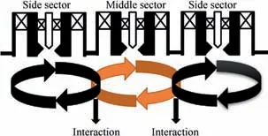
Fig. 6 Interactions between sectors.
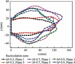
Fig. 7 Comparison of recirculation zone of Plane 1 and Plane 5 under pressure drop of 3%.
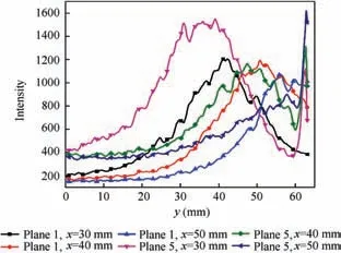
Fig. 8 Radial distribution of fuel at different axial positions when swirl number is 0.7.
Fig.8 shows the radial distribution of fuel at different axial positions when the swirl number is 0.7. It can be seen that the fuel distribution intensity at an axial position of 30 mm from the exit of swirler is larger than that of 40 mm and 50 mm.With the increase of axial position, the radial position where the fuel distribution intensity reaches the maximum becomes larger, whereas the maximum fuel distribution intensity becomes smaller. The main reason is that after the fuel is sprayed through the pressure-swirl atomizer, part of the fuel impact the venturi wall to form a film,which still has a certain swirl velocity at the exit of the swirler. The film is further atomized by the two-stage counter-rotating air at the exit of the swirler.The droplets follow the swirl air in the radial direction.Therefore,the larger the axial position is,the better spray performance becomes, and the smaller maximum intensity of the fuel distribution becomes.
3.2. Influence of swirl intensity on spray characteristics of Plane 3
Figs.9 and 10 show the spray structures and flow fields of different swirl intensities of Plane 3 under pressure drop of 3%and fuel-air ratio of 0.02.
Fig. 9 shows that the fuel distribution of Plane 3 is more uniform than that of Plane 1 and Plane 5.The fuel distribution is influenced by the flow field.It can be seen in Fig.10 that the velocity of Plane 3 is small,especially the radial velocity which is induced by the interactions between the flow fields of sectors.The interactions between the flow fields make the swirl intensity attenuate greatly, and affect the development of the swirl in the direction of radial.
From Fig. 9, it can be seen that the fuel distribution area and the amount of fuel in Plane 3 when the swirl number is 0.9 are larger than those when the swirl number is 0.5, 0.7.The reason may be that the flow field expansion angle becomes larger with the increase of swirl intensity, and more droplets follow the air flow to a larger radial position.
3.3.Influence of FAR on spray characteristics of plane 1(model:M = 0.7)
Fig.11 shows the spray characteristics of Plane 1 under different fuel-air ratios and pressure drop of 3%.
The fuel distribution intensity in the center area of the main combustion zone and the width of spray cone (h) become larger with the increase of fuel-air ratio. When the fuel-air ratio is bigger, the primary atomization is better and more droplets follow the swirl air directly into the center area of the main combustion zone. The spray cone angle under different fuel-air ratios are absolutely the same. The main reason may be that the flow field plays a decisive role in the forming of spray structure. In addition, it can be seen that the axial fuel penetration depth becomes larger with the increase of fuel-air ratio, which is mainly induced by the higher fuel velocity.

Fig. 9 Comparison of spray structures of different swirl intensities of Plane 3.

Fig. 10 Comparison of flow fields of different swirl intensities of Plane 3.

Fig. 11 Spray characteristics of Plane 1 under different FARS and pressure drop of 3%.
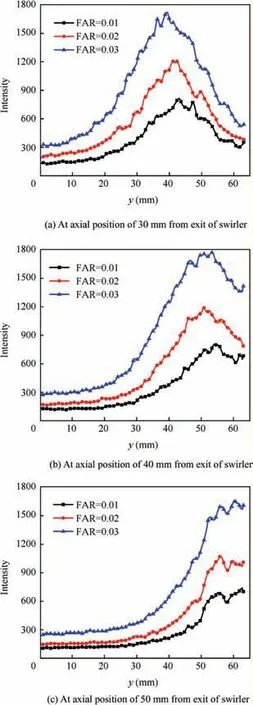
Fig. 12 Radial distribution of fuel under different fuel-air ratios.
Figs. 12(a)-(c) show the radial distribution of fuel at the axial position of 30, 40, 50 mm from the exit of swirler under different fuel-air ratios. At the same axial position, the radial position where the fuel distribution intensity reaches the maximum is substantially the same, which further illustrates that the spray cone angles are absolutely the same under different fuel-air ratios.And the radial position where the fuel distribution intensity reaches the maximum becomes larger with the increase of axial position. The maximum fuel distribution intensities at different axial positions(30,40,50 mm)are absolutely the same, which illustrates that the air has small influence on the fuel distribution intensity inside the spray cone.
3.4. Spray characteristics of middle sector (model: M=0.7)
Fig. 13 shows the spray characteristics of the middle sector under pressure drop of 3% and fuel-air ratio of 0.02, three planes of the middle sector are analyzed. Fig. 14 shows the flow field characteristics of the middle sector under pressure drop of 3%.
As shown in Fig.13,a hollow spray cone is formed in Plane 1, the fuel distribution intensity on the cone is large and the fuel distribution intensity in the center area of Plane 1 is very small. The fuel distribution of Plane 2 is no longer a hollow spray cone, there is a droplet accumulation area with a crescent-shape. The fuel distribution in Plane 3 becomes more uniform and the distribution area becomes larger, which is mainly induced by the flow field of Plane 3 (as shown in Fig. 14). Comparing the flow field and the spray field in Figs.13 and 14, it can be found that the fuel distribution area becomes larger with the decrease of recirculate intensity.
In general, the fuel distribution of Plane 1 is hollow spray cone, and the hollow spray cone disappears gradually and the fuel distribution area becomes larger and more uniform as the plane away from Plane 1.
4. Conclusions
In this paper, the spray characteristics of a double-swirl lowemission combustor are analyzed by using PIV technology and PLIF technology in the optical three-sector combustor test rig. The interaction between sectors and the influence of swirl intensity on spray structure are explained. The results show:

Fig. 13 Spray characteristics of middle sector under pressure drop of 3% and fuel-air ratio of 0.02.

Fig. 14 Flow field of middle sector under pressure drop of 3%.
(1) The swirl intensity has a great effect on the flow field and spray structure. The spray cone angle when the swirl number is 0.7, 0.9 is bigger than that when the swirl number is 0.5 as the small expansion angle induces large radial velocity loss of droplets. The fuel distribution zone is larger and the distribution is more uniform when the swirl number is 0.5 as the expansion angle and the width of recirculation zone are small, whereas it is not good to the ignition.
(2) The fuel concentration in the center area of Plane 5 is larger than that of Plane 1 as more amount of fuel will be in the recirculation zone when the width of the recirculation zone is larger,and the spray cone angle in Plane 5 is larger than that in Plane 1 as the expansion angle is larger.
(3) The flow field structure has a great influence on the spray structure. The spray cone is mainly formed by the high-speed jet as the droplets are following the swirl air. There are interactions between the flow field and the spray field, and the recirculation zone has a great influence on the fuel distribution in the center area.
(4) The fuel distribution of Plane 3 is more uniform than that of Plane 1 and Plane 5. The fuel distribution area and the amount of fuel in Plane 3 when the swirl number is 0.9 are larger than those when the swirl number is 0.5,0.7 as the flow field expansion angle becomes larger with the increase of swirl intensity, and more droplets follow the air flow to a larger radial position.
(5) The fuel distribution of Plane 1 is hollow spray cone,and the hollow spray cone disappears gradually and the fuel distribution area becomes larger and more uniform as the plane away from plane 1.
(6) The width of spray cone becomes larger with the increase of fuel-air ratio, whereas the spray cone angle under different fuel-air ratios are absolutely the same.
Acknowledgments
This work is supported by the National Natural Science Foundation of China (Nos. 51306182 and 51406202).
 CHINESE JOURNAL OF AERONAUTICS2020年2期
- CHINESE JOURNAL OF AERONAUTICS的其它文章
- Delaying stall of morphing wing by periodic trailing-edge deflection
- Optimization and verification of free flight separation similarity law in high-speed wind tunnel
- Non-intrusive reduced-order model for predicting transonic flow with varying geometries
- Consideration on aircraft tire spray when running on wet runways
- Aeroelastic simulation of the first 1.5-stage aeroengine fan at rotating stall
- Experimental study on NOx emission correlation of fuel staged combustion in a LPP combustor at high pressure based on NO-chemiluminescence
