Mach reflection in steady supersonic flow considering wedge boundary-layer correction
Zijun CHEN, Chenyun BAI,b, Ziniu WU,*
a Department of Engineering Mechanics, Tsinghua University, Beijing 100084, China
b Institute of Aeroengine, Tsinghua University, Beijing 100084, China
KEYWORDS Boundary-layer correction;Mach reflection;Shock waves;Supersonic flow;Viscous effect
Abstract Mach reflection in steady supersonic flow is an important phenomenon having received extensive studies, among which simplified theoretical models to predict the size of Mach stem and other flow structure are of particular interest. Past efforts for such models were based on inviscid assumption while in real cases the flow is viscous. Here in this paper we consider the influence of wedge boundary layer on the Mach stem height. This is done by including a simplified boundary layer model into a recently published inviscid model. In this viscous model, the wedge angle and the trailing edge height,which control the Mach stem height,are replaced by their equivalent ones accounting for the displacement effect of the wedge boundary layer, with the boundary layer assumed to be laminar or fully turbulent.This viscous model is shown to compare well with numerical results by computational fluid dynamics and gives a Mach stem height as function of the Reynolds number and Mach number.It is shown that due to the viscous effect,the Mach stem height is increased, through increasing the effective wedge angle.
1. Introduction
Shock reflection in steady supersonic flow is a well-studied phenomenon.1As shown in Fig. 1,2a wedge of length w and angle θwinduces an incident shock wave(i),which reflects from the reflecting surface.When the wedge angle is large enough or the inflow Mach number Ma0is small enough, the reflected shock wave detaches and a special reflection configuration,called irregular reflection or Mach reflection (since this was first observed by Mach3), occurs.
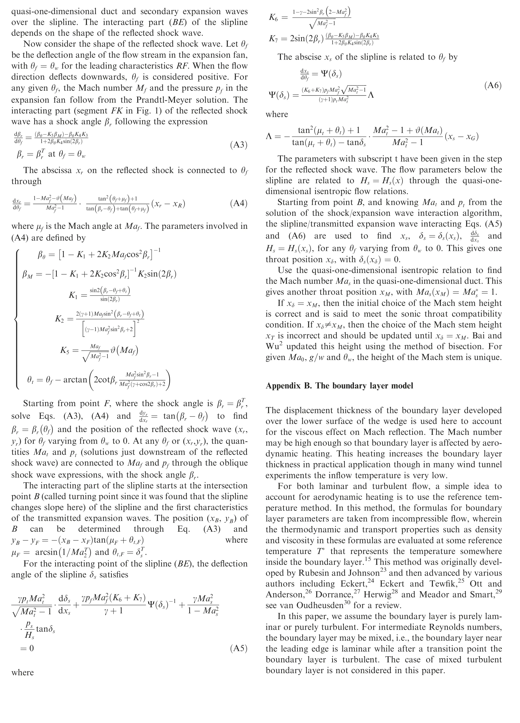
Mach reflection has a three-shock structure. A triple shock point(T)connects these three shock waves, including the incident shock wave (i), the reflected shock wave (r) and a strong shock wave called Mach stem (m). A slipline (s), generated from the triple point, separates the flows downstream of the reflected shock wave and Mach stem and across this slipline the pressure is balanced.The slipline and the reflecting surface enclose a flow region that can be regarded as quasi-onedimensional.4-7The transmitted expansion waves from the trailing-edge (R) intersect this slipline and reduces the pressure,so that the quasi-one-dimensional region or duct has a sonic throat.The three shock waves and the slipline separate the flow into four regions,the solutions of which in the vicinity of the triple point can be found using the three-shock theory of von Neumann.8
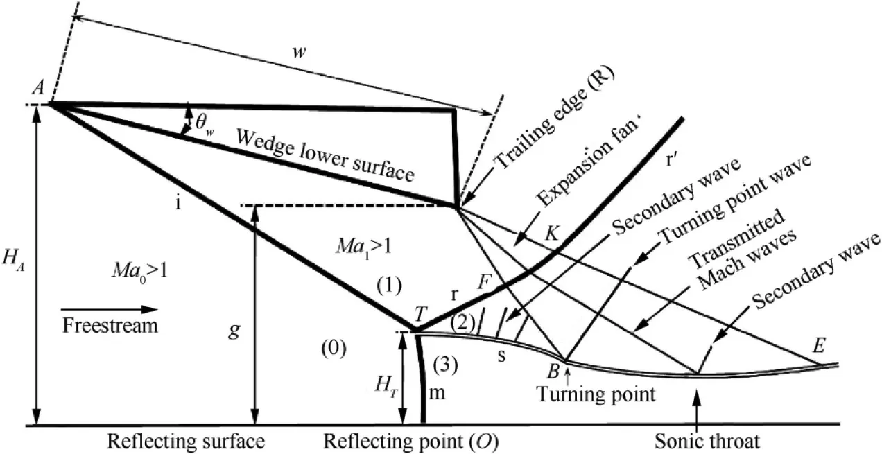
Fig. 1 Mach reflection configuration following Bai and Wu2. The reflection of the incident shock wave (i) produces a reflected shock wave(r)composed of a free segment(TF),an interacting segment(FK)and another straight segment(r’),a strong shock wave called Mach stem(m),and a slipline(s)(composed of a free segment TB and an interactive segment BE).Secondary Mach waves are generated over the slipline. A sonic throat exists in the quasi-one-dimensional flow region below the slipline.
The mechanism by which the size of the Mach stem is determined has been a long-standing problem. This problem was initially raised by Courant and Friedrichs9(see also Liepmann and Roshko10)and about forty years later it was still regarded as unsolved by Emanuel,11see also Ben-Dor and Takayama.12Azevedo and Liu4proposed for the first time a physical model for predicting the Mach stem height. In this model, the sonic throat is assumed to occur where the leading Mach wave of the expansion fan intersects the slip stream and the flow below the slipline is treated using the isentropic quasi-onedimensional ideal gas flow theory. Li and Ben-Dor13allowed the sonic throat to occur further downstream and assumed that the Mach stem (m), the reflected shock wave (r) and the slipline (s) are slightly curved to be modelled by second order polynomials. Mouton and Hornung6constructed a model for the growth rate of the Mach stem height during the transition and obtained the Mach stem height as the transition is finished. They assumed that the Mach stem, the reflected shock wave, the slipline and the Mach waves to be straight lines.Gao and Wu7observed from numerical simulation that secondary Mach waves are generated over slipline to balance the pressure decrease below the slipline and built a characteristic theory to account for the influence of these secondary waves. Bai and Wu2further derived analytical expressions for the shape of slipline and reflected shock wave and found that the slipline changes slope at the turning point (B) where the leading Mach wave of the expansion fan intersects the slip stream. They then believed that a turning point wave, in the form of a weak shock wave, is generated from this turning point.
Recently, Schmisseur and Gaitonde14performed a numerical study of the Mach stem height taking into account the effect of viscosity. Mach stem heights from inviscid and viscous flow calculations using Computational Fluid Dynamics(CFD) are compared and it was found that viscosity increases the Mach stem height. They pointed out that the increase of the Mach stem height is due to the increased displacement effect of the wedge boundary-layer and suggested that further work is essential to confirm this hypothesis.
In both experimental and numerical studies for the Mach stem height in viscous flow conditions, one often uses the shock angle as input condition,making the influence of viscosity unclear. The boundary layer developed over the lower surface of the wedge not only increases the effective wedge angle and but also reduces the effective height of the wedge trailing edge. Measuring the shock angle automatically includes the influence of the boundary layer in increasing the shock angle,but the effect of the reduced effective trailing-edge height is not considered.
Though the displacement thickness of boundary layer is small so that the increase of the effective wedge angle and the decrease of the effective trailing-edge height may be small,its influence on Mach stem may be large since the dependence of the Mach stem height on the geometrical parameters is very sensitive, especially when the Mach stem height is small.13
The purpose of this paper is therefore to built a viscous Mach reflection model for Mach stem height, to account for the influence of the boundary layer developed over the lower surface of the wedge. This influence is expected to be important when the Reynolds number is low(since the displacement thickness of the boundary layer increases for decreasing Reynolds number) or when the Mach number is large (since aerodynamic heating for large Mach number increases the boundary layer thickness15).In the present paper,the reflecting surface is considered as an inviscid one (as in the case of the symmetrical plane of Mach reflection by intersection of two shock waves from opposite sides). For viscous reflecting surface as in the case of a solid wall, the problem is complicated by shock wave/boundary layer interaction.16

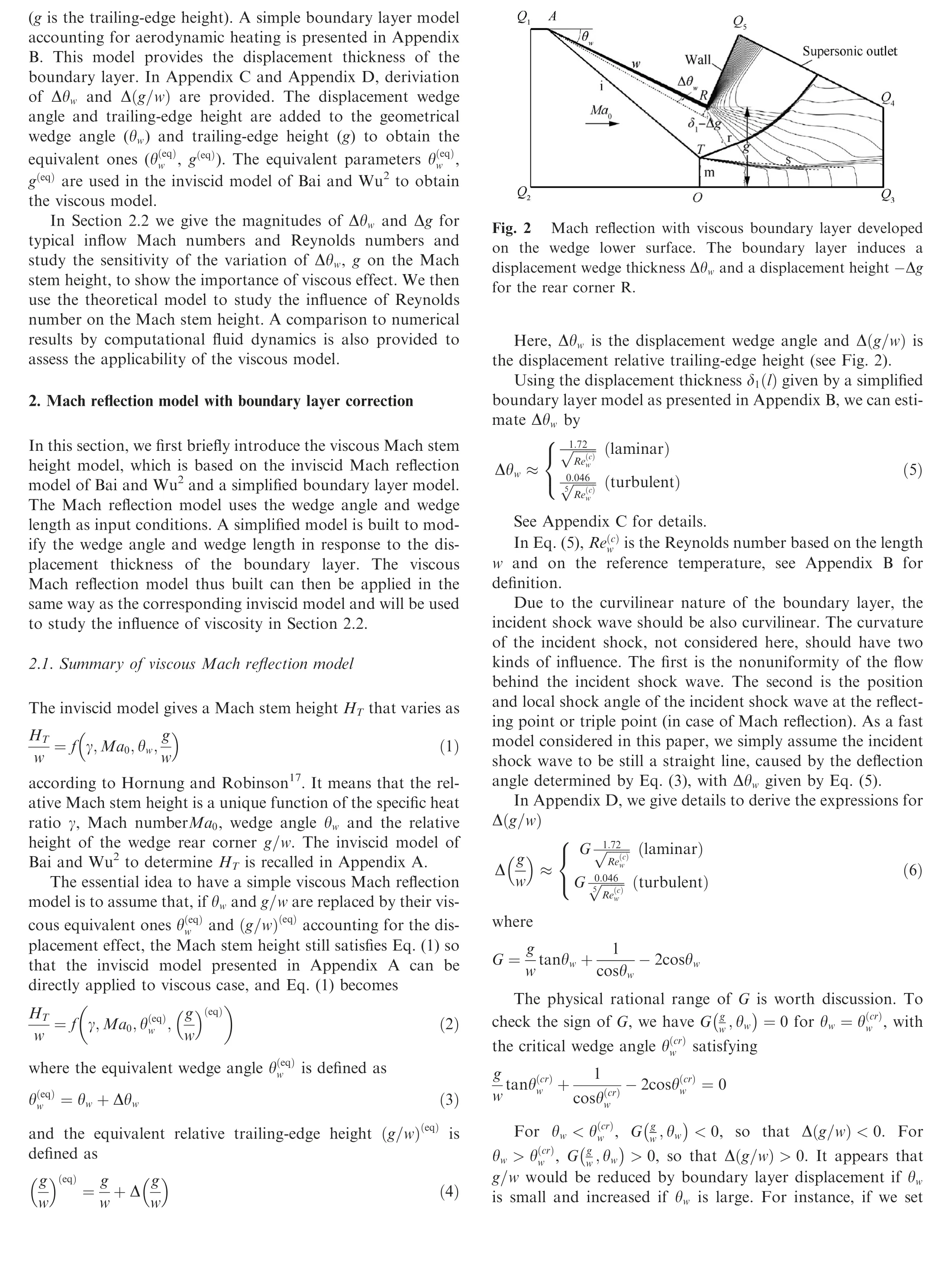

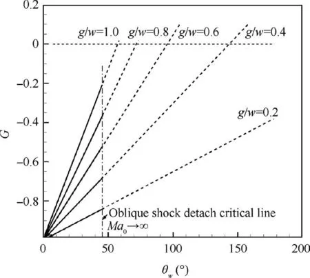
Fig. 3 Value of G(g /w,θw ) for various g/w and θw.
2.2. Influence of boundary layer on Mach stem height
For purpose of clarifying the importance of boundary layer,the magnitudes of the displacement wedge Δθwangle and displacement relative trailing-edge height Δ ( g/w) for a typical range of Reynolds numbers are computed and the sensitivity of the Mach stem height to the wedge angle and trailingedge height is studied. The viscous Mach reflection model is then used to study the viscous effect(Reynolds number effect)on Mach stem height. These studies are performed using the theoretical model and are presented in Sections 2.2.1-2.2.3.The influence of the boundary layer is further studied using CFD, which is also used to verify the accuracy of the theoretical models. The CFD method is presented in Section 3.1. A comparison of inviscid and viscous CFD solutions is given in Section 3.2. The comparison between theory and CFD is displayed in Section 3.3.
2.2.1. Magnitudes of displacement wedge parameters
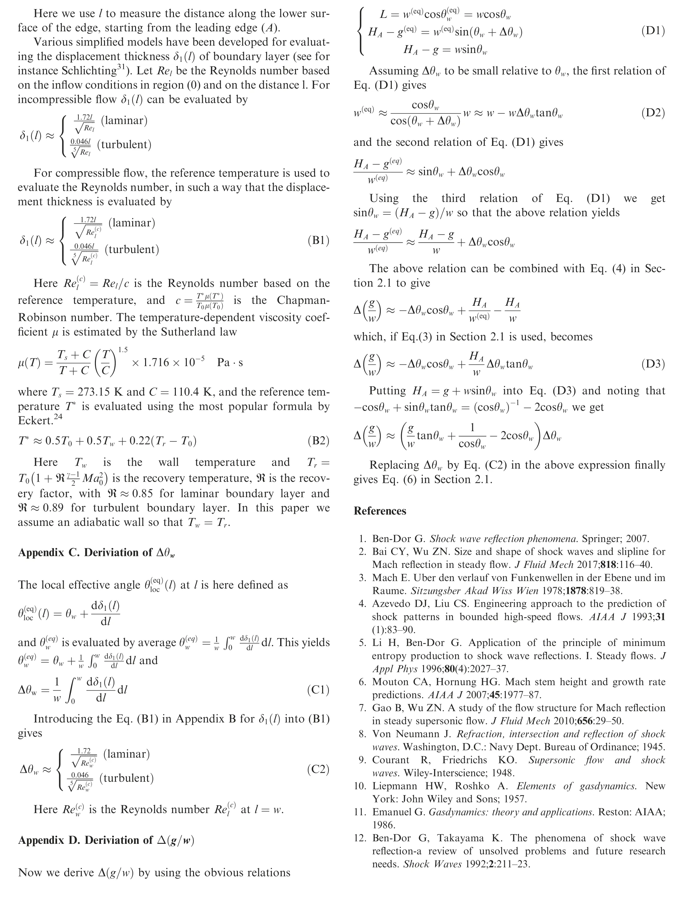
Fig.4 displays the displacement wedge angle Δθwcomputed by Eq. (5) and the relative displacement trailing-edge height Δ (g/w ) computed by Eq. (7). The Reynolds number Rew=varies from 105to 107. The parameters θw=22◦,g/w=0.4, Ma0=2.84 and 4.96 are taken from Hornung and Robinson.17
Consider the boundary layer to be laminar.For the effect of Reynolds number, the absolute value of Δθwand Δ (g/w )increase when Rewdecreases or Ma∞increases,due to thickening of the boundary layer by aerodynamic heating at large Mach number. For instance, when Ma0=2.84 is fixed and Rewvary from 107to 105, Δ ( g/w) changes from -0.0018 to-0.0183 and Δθwchanges from 0.1 deg to 0.4°.
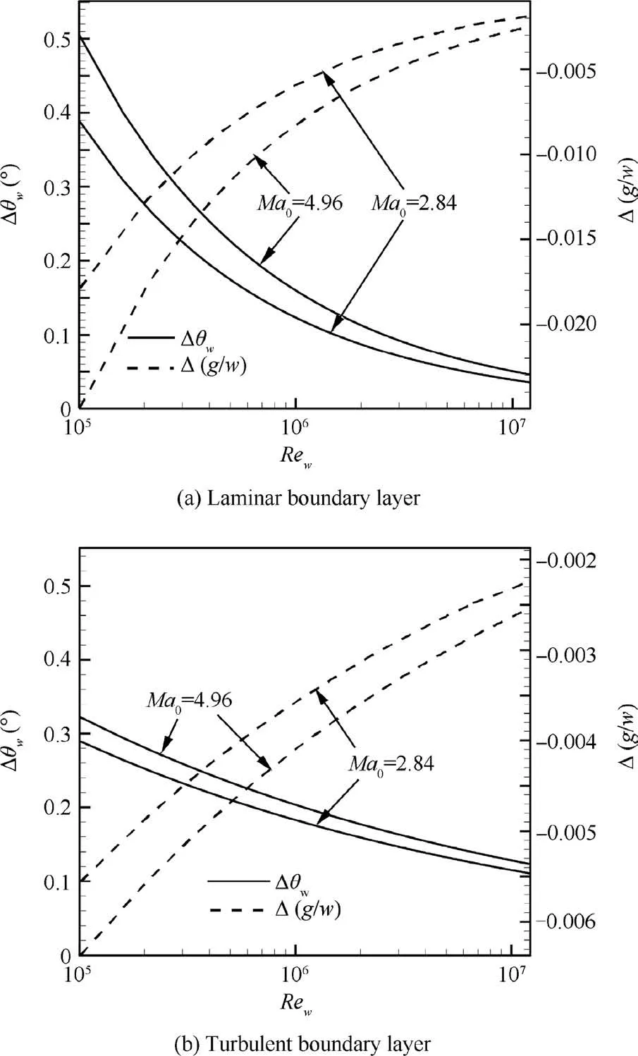
Fig. 4 Influence of Reynolds number on displacement wedge parameters Δθw and Δ ( g/w) for θw =22◦andg/w=0.4 at Mach numbers Ma∞=2.84, 4.96.
For turbulent boundary layer, the absolute value of Δθwand Δ (g/w ) is smaller than that for laminar flow when Reynolds number is less than 107. For instance, the quantity Δθw≈0.12° and Δ ( g/w)≈-0.0024 for Rew=107, and increases to Δθw≈0.29°and Δ (g/w )≈-0.0055 for Rew=105.
Though the amount of Δθwappears to be small, its influence on the Mach stem height will be high, as is clear below.
2.2.2. Mach stem height for various wedge parameters
Fig.5 shows the dependence of the Mach stem height on each factor (θw, g/w), computed by the inviscid Mach refection model of Bai and Wu2, as summarized in Appendix A. To see the influence of θw, we set Ma0=2.87, 3.49, 3.98, 4.96 and g/w=0.4. It is seen that the relative Mach stem height HT/w increases monotonically with θw. When θwchanges 1°,HT/w may change by 25% to more than 100%, especially when θwis small. The displacement wedge angle Δθwmay be in the order of 1°, as seen from Fig. 4. Hence, it is expected that the viscous boundary layer on the wedge lower surface may have a significant influence on the Mach stem height,especially when θwis small and the Mach number is large.
For the influence of the relative trailing-edge height g/w,we set Ma0=2.87, 3.49, 3.98, 4.96 and θw= 22◦. It is seen that HT/w increases almost linearly with decreasing g/w, for the condition considered here. Thus, the Mach stem height is less sensitive to g/w compared to θw.
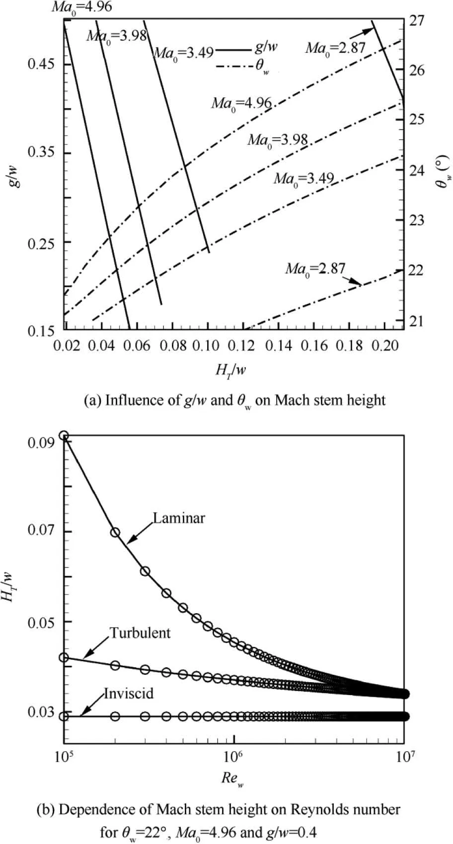
Fig. 5 Mach stem height.
Thus the influence of the boundary layer on the Mach stem height is majorly due to the increase of the equivalent wedge angle.
2.2.3. Effect of Reynolds number
Now we study the influence of viscous effect, in terms of the Reynolds number, on the Mach stem height using the present viscous Mach reflection model (Section 2.1). The inviscid model of Bai and Wu2as summarized in Section 2.1 is applied by replacing θwand g/w with the equivalent θ(eq)wand (g/w )(eq),see Eqs.(3)and(5)for,Eqs.(4)and(6)for (g /w)(eq).The boundary layer is either assumed fully laminar or fully turbulent, though in real applications the boundary layer may be mixed laminar-turbulent.
Fig. 5(b) gives the Mach stem height for Reynolds number Rewranging from 105to 107, with θw= 22◦, Ma0=4.96,g/w=0.4. Compared to inviscid mode, the increase of Mach stem height due to viscous effect is large, especially for small Reynolds number and for turbulent boundary layer. For instance, at Rew=106, the viscous model gives a Mach stem height HT/w≈0.034 for turbulent boundary layer and HT/w≈0.033 for laminar boundary layer, compared to HT/w≈0.029 for inviscid flow. For small Reynolds number,the turbulent model predicts a Mach stem height smaller than the laminar one, noting that for such small Reynolds number the boundary layer should be laminar. For Rew>1.04×10⁷the turbulent model gives a larger Mach stem height, conversely. When Reynolds number tends to infinity, boundary layer thickness tends to zero according to Eq.(B1), and there is no difference between inviscid, laminar and turbulent model’s prediction.
3. Results analysis
3.1.Method and boundary conditions for numerical computation
For numerical simulation, we use the experimental conditions of Ivanov et al.18who measured the transition for symmetric reflection in a low-noise wind tunnel. Specifically, we use Ma0=4, g/w=0.43 and Rew=3.83×10⁵(the Reynolds number based on unit length is 1.278×10⁷). The temperature is T0=65 K and the pressure is 1641 Pa. Note that Ivanov et al.18did not provide these conditions for temperature and pressure and we find these conditions from their previous work. Two wedge angles, θw= 23.21◦, 24.60◦, are used for inviscid and viscous computations.
For numerical simulations of inviscid flow, the compressible Euler equations in gas dynamics are solved using the second order Roe scheme.19For viscous flow, the compressible Navier-Stokes equations are solved,with the inviscid part also solved using the second order Roe scheme and with the viscous part solved using the second order central difference scheme.For turbulence modelling in viscous flow computation, the SST two equation model20is used. All these methods exist in the commercial code Fluent and it is this code that is used for CFD simulation here.
The grid used contains 1600 points along the horizontal direction and 700 points along the vertical direction.This grid is much denser than the grid used before by other authors.For instance, Gao and Wu7used a grid with 300×200 points and Wu et al.21used grid with 1540×400 points. The grid is refined near the triple point structure and near the wedge lower surface to capture the boundary layer.
As displayed in Fig. 2 for boundary conditions, Q1Q2is a supersonic inlet, AQ1is a symmetry, Q2Q3is also a symmetry(reflecting surface),no-slip and adiabatic wall condition is prescribed along AR and RQ5, Q3Q4is a supersonic outlet, and Q4Q5is a nonreflecting boundary.
Note that RQ5is the backside of the wedge similar to the geometry of Ivanov et al.18who used a triangular wedge and Q5is the upper rear corner of this wedge.
3.2. Comparison between inviscid and viscous numerical results
Fig. 6 displays the Mach contours obtained by both inviscid and viscous simulations (the same θwis used). Differences of shock angles are observed for inviscid and viscous flows. The shock angle of the incident shock wave is larger in viscous flow than that in inviscid flow. The Mach stem height in viscous flow is higher than that in inviscid flow, as predicted theoretically above. Shock structures given by current viscous theory are also displayed, and match well with viscous numerical results.
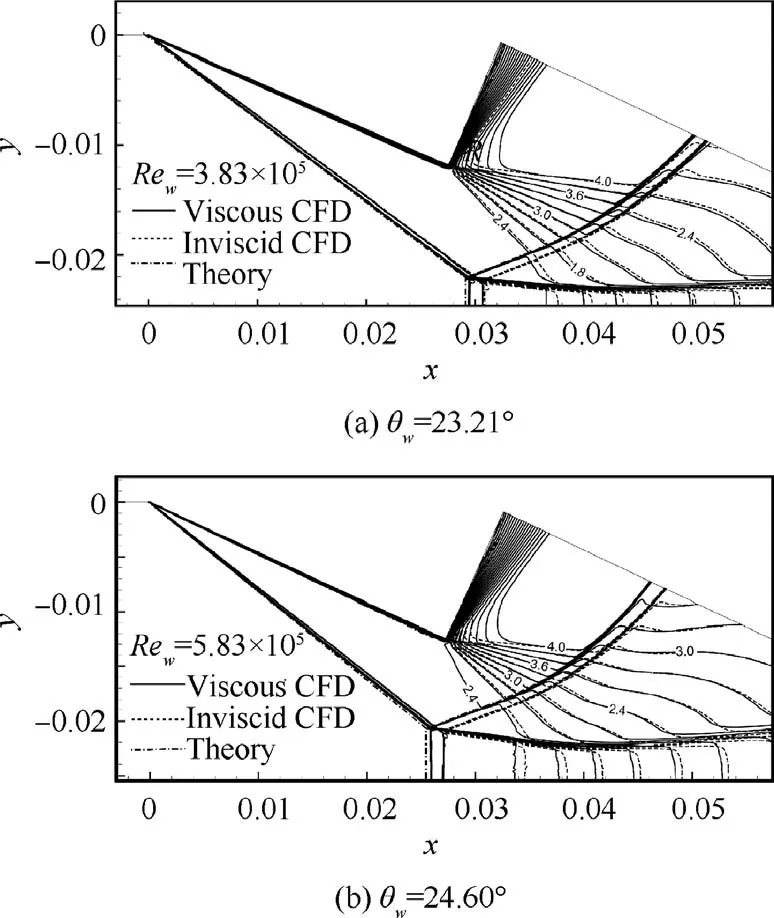
Fig.6 Mach contours by inviscid and viscous flow computations for Ma0 =4.
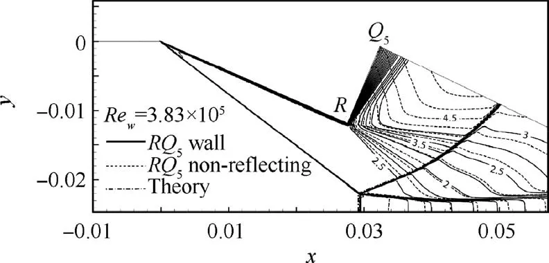
Fig. 7 Mach contours by viscous flow computations with RQ5 treated as wall and non-reflecting boundary for Ma0 =4 and θw =23.21◦.
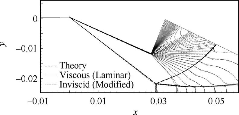
Fig.8 Comparison of Mach contours between the viscous CFD result (with θw =23.21◦) and modified inviscid CFD result(θw =23.21◦+ Δθw, g/w=0.43 + Δ ( g/w), where Δθw =0.23◦and Δ (g/w )=-0.0022) for Ma0 =4.
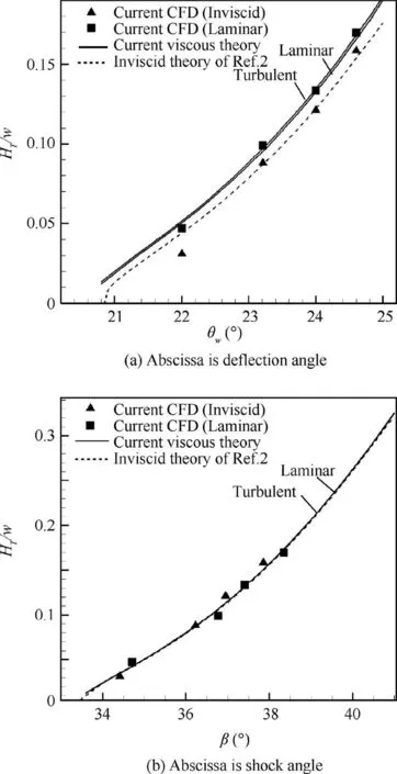
Fig. 9 Comparison between theory and CFD simulation for Mach stem height at Ma0 =4,g/w=0.43 and Rew =3.83×10⁵.
Note that there is also a boundary layer along RQ5for viscous flow.To see the influence of this boundary layer,we also computed the flow where RQ5is replaced by a non-reflecting wall. Fig. 7 displays a comparison of Mach contours with RQ5treated as a wall and a non-reflecting boundary, for viscous flow with θw=23.21◦. It is seen that the Mach stem height is almost the same for both treatments of RQ5, at least for the conditions considered.
It is interesting to see whether the viscous numerical result can be reproduced through inviscid one with correction of thewedge parameters. In Fig. 8, we compare, for Ma0=4,θw=23.21◦, viscous CFD result with an inviscid one where θwis augmented by Δθwthrough Eq.(5) (Δθw=0.23◦in this case) and g/w is changed by Δ( g/w ) through Eq. (6)(Δ( g/w )=-0.0022 in this case).The close agreement indicates that a simple boundary model correcting the inviscid model is suitable for the present study.

Table 1 Comparison between theory and numerical simulation for Ma0 =4,Rew=3.83×10⁵ and g/w=0.43.The theoretical results are obtained by the model of Bai and Wu (2017)2 for inviscid flow and the present viscous model for viscous flow.
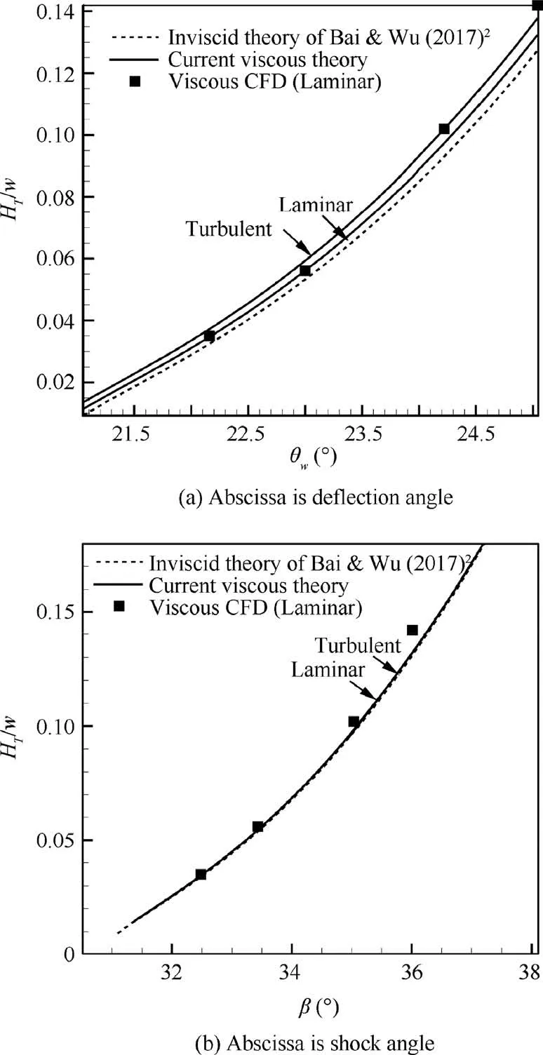
Fig. 10 Influence of viscous effect on Mach stem height at Ma0 =4.96, g/w=0.4 and Rew =1.36×10⁶.
3.3. Comparison between theory and numerical results
Table 1 displays the comparison between theory and numerical results for the shock angle and relative Mach stem height.For a given θwand Ma0,the shock angle β of inviscid flow is computed by the shock angle relation:

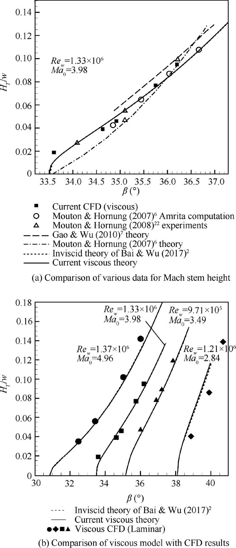
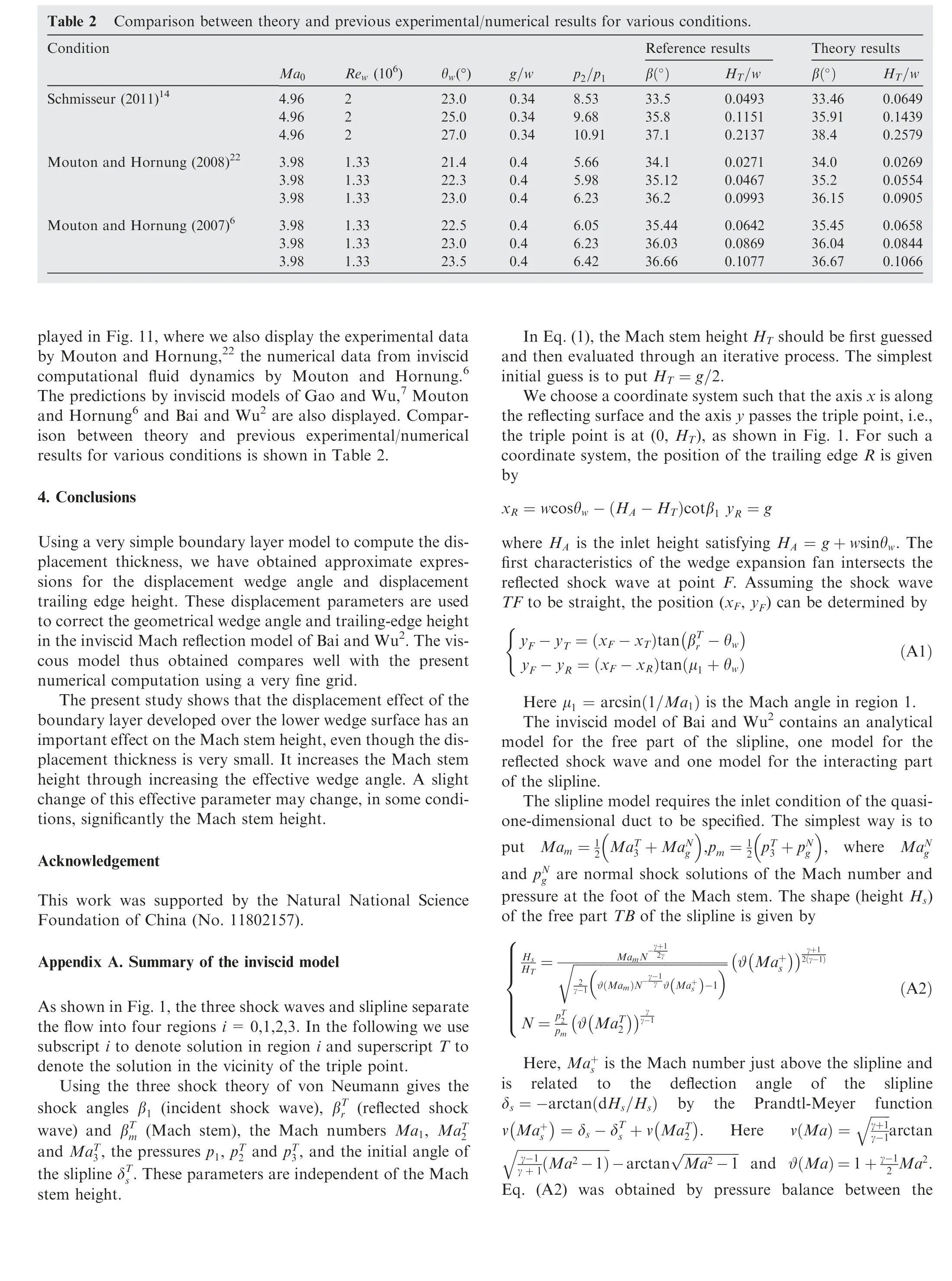
Fig. 11 Further comparison and validation for current viscous model.
For viscous flow,the Eq.(5)is used to find the displacement wedge angle Δθwand then θwis replaced by θw+Δθwin the above relation to obtain the shock angle in viscous flow. As shown in Table 1,the shock angles obtained using such simplified models match very well with the CFD results. The displacement effect of the boundary layer enlarges the shock angle by an amount close to 0.5◦. Good comparison is obtained for the relative Mach stem height HT/w, according to Table 1 and Fig.9.Fig.9(a)displays the Mach stem height for θwand shows difference of HT/w at any given θw.Both theory and CFD shows that the Mach stem height is increased by viscous boundary layer developed on the lower wedge surface.Fig. 9(b), which displays the Mach stem height for the shock angle, shows no difference between inviscid and viscous models,since the displacement effect of the boundary layer is automatically included in the shock angle.

 CHINESE JOURNAL OF AERONAUTICS2020年2期
- CHINESE JOURNAL OF AERONAUTICS的其它文章
- Delaying stall of morphing wing by periodic trailing-edge deflection
- Optimization and verification of free flight separation similarity law in high-speed wind tunnel
- Non-intrusive reduced-order model for predicting transonic flow with varying geometries
- Consideration on aircraft tire spray when running on wet runways
- Aeroelastic simulation of the first 1.5-stage aeroengine fan at rotating stall
- Experimental study on NOx emission correlation of fuel staged combustion in a LPP combustor at high pressure based on NO-chemiluminescence
