Virtual target guidance-based distributed model predictive control for formation control of multiple UAVs
Zhiho CAI, Longhong WANG, Jing ZHAO,*, Kun WU, Yingxun WANG
a School of Automation Science and Electrical Engineering, Beihang University, Beijing 100083, China
b Flying College, Beihang University, Beijing 100083, China
KEYWORDS Distributed Model Predictive Control (MPC);Event-triggered mechanism;Formation control;Obstacle avoidance;
Abstract The paper proposes a Virtual Target Guidance (VTG)-based distributed Model Predictive Control (MPC) scheme for formation control of multiple Unmanned Aerial Vehicles (UAVs).First, a framework of distributed MPC scheme is designed in which each UAV only shares the information with its neighbors, and the obtained local Finite-Horizon Optimal Control Problem(FHOCP) can be solved by swarm intelligent optimization algorithm. Then, a VTG approach is developed and integrated into the distributed MPC scheme to achieve trajectory tracking and obstacle avoidance.Further,an event-triggered mechanism is proposed to reduce the computational burden for UAV formation control,which takes into consideration the predictive state errors as well as the convergence of cost function. Numerical simulations show that the proposed VTG-based distributed MPC scheme is more computationally efficient to achieve formation control of multiple UAVs in comparison with the traditional distributed MPC method.
1. Introduction
In recent years,Unmanned Aerial Vehicles (UAVs) have been widely used in military and civilian fields, such as reconnaissance, surveillance, rescue, forestry fire prevention, and urban mapping.1-4Compared to single UAV platform, multiple UAVs have better performance in complex missions,including cooperative target searching, rescue, and combat.5-8Formation control has many advantages in detection, localization and perception,which may contribute to efficiency task allocation, aerial refueling, self-organizing and reconfiguration for multiple UAVs.
The common approaches of formation control for multiple UAVs include consensus theory, leader-follower strategy,behavior-based method, virtual structure approach, differential game,finite-time control theory,etc.9-12In Ref.13,a formation control algorithm for both leaders and followers is designed, in which leaders are implicitly integrated into the swarm and can be influenced by navigational feedback from their flock mates. Based on the sliding mode control method,a distributed multi-UAV formation control method is proposed in Ref.14. The formation can be achieved in finite time when the states of a multi-UAV system are on the sliding mode surface.Based on homing pigeon hierarchical strategies,a distributed formation control framework is proposed in Ref.15,which combines the advantages of velocity correlation,leader-follower interaction and hierarchical leadership network observed in pigeon flock with altitude consensus control algorithm.In Ref.16,a collision avoidance control algorithm is proposed on the basis of the virtual structure and artificial potential field method. The leader-follower control strategy in 3-D space is designed to effectively avoid the obstacle and track the motion target.In Ref.17,a switching approach based on the binary-tree network is developed to realize the transformations between the V-shape and the complete binary tree shape topologies. The formation control problem is formulated and solved as a differential game problem. In Ref.18, a distributed formation control algorithm based on edge Laplacian consensus is proposed considering the autopilot and the longitudinal decoupling nonlinear UAV model. Based on the finite-time control theory,a distributed formation control protocol is proposed in Ref.19.The multi-UAV systems are able to achieve the desired formation in a limited time,and according to the requirements of formation control, the formation configurations can be specified in advance.
The Model Predictive Control(MPC)approach also shows good performance in UAV formation control.20-22In Ref.23,a collision-free formation controller is designed, and based on MPC scheme, an online three-dimension path planning method is proposed for multiple UAVs.24In addition, the linear and nonlinear control strategies are applied as a high-level controller for multiple UAVs to track the expected target in numerical simulations and flight experiments.25However,most MPC schemes for cooperative flight control are designed on the basis of time-triggered mechanism. The control actions are periodically executed even if the systems have achieved desired control performance. In recent years, event-triggered mechanism has been demonstrated to be an effective tool to reduce computational load and communication consumption in robot control, motor control, and networked control systems.26-31For multiple nonholonomic robots,26the distributed event-triggered optimization method is proposed to minimize the global battery energy consumption. The cost function of each robot depends on the state of the hand position and represents battery energy consumption. The distributed eventtriggered mechanism is designed such that the states of hand positions converge exponentially. For motor control,28an event-triggered high-gain-observer-based output feedback control scheme is proposed on the basis of separate eventtriggering conditions, which only depends on the measurable signals. Asymptotic upper bounds of the observation error and the system states are obtained, and explicit relationships between these upper bounds and the parameters in the event triggering conditions are characterized. For networked control,30a novel event-triggered globalized dual heuristic programming method is proposed to reduce the required samples and guarantee the stability of the system. The networked control systems can communicate and update the control law only when the designed event-triggered condition is violated. Therefore, event-triggered mechanism is integrated into the MPC scheme to reduce computational load and communication consumption for formation control of multiple UAVs. Based on the above work, this paper proposes a distributed MPC scheme for UAV formation control with event-triggered mechanism, which can enable the Finite Horizon Optimal Control Problem (FHOCP) to be solved asynchronously and reduce the computational burden. Besides,accurate trajectory tracking and obstacle avoidance are important to formation control of multiple UAVs, and therefore, a Virtual Target Guidance (VTG)-based approach is developed and integrated into the distributed MPC scheme.
The main contribution of the paper is described in the following: (A) a framework of distributed MPC scheme is designed in which each UAV only shares the information with its neighbors;(B)a VTG approach is developed and integrated into the distributed MPC scheme to achieve trajectory tracking and obstacle avoidance; (C) an event-triggered mechanism is proposed to reduce the computational burden for UAV formation control. The paper is organized as follows. Section 2 presents the preliminaries including the formation model,constrained Particle Swarm Optimization (PSO) solver, and nonlinear MPC.In Section 3,the design of the VTG-based distributed MPC scheme is proposed in detail. In Section 4, the numerical simulations demonstrate the effectiveness of the VTG-based proposed distributed MPC scheme. Finally, concluding remarks are presented in Section 5.
2. Preliminaries
2.1. UAV motion model
In this section, the motion model of UAV is introduced. Suppose that a group of UAVs form the desired formation in a two-dimensional plane, and the number of UAVs is NU.Each UAV is assumed to be a mass point. The motion states of the UAV i can be expressed as follows

where pi=[pix,piy]Tis the position of UAV i.viand θiare linear velocity and yaw angle, respectively. ωiis the angular velocity.aiis the accelerated velocity.The UAV motion model is shown in Fig. 1.
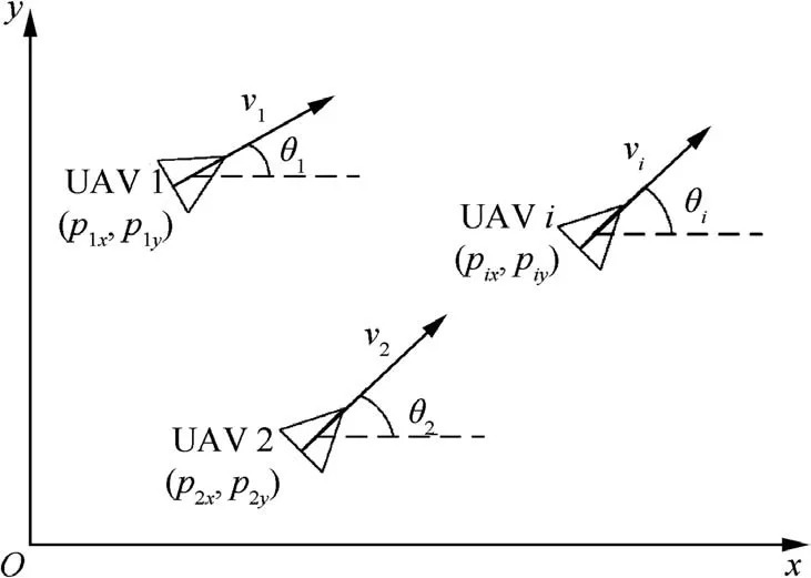
Fig. 1 UAV motion model.
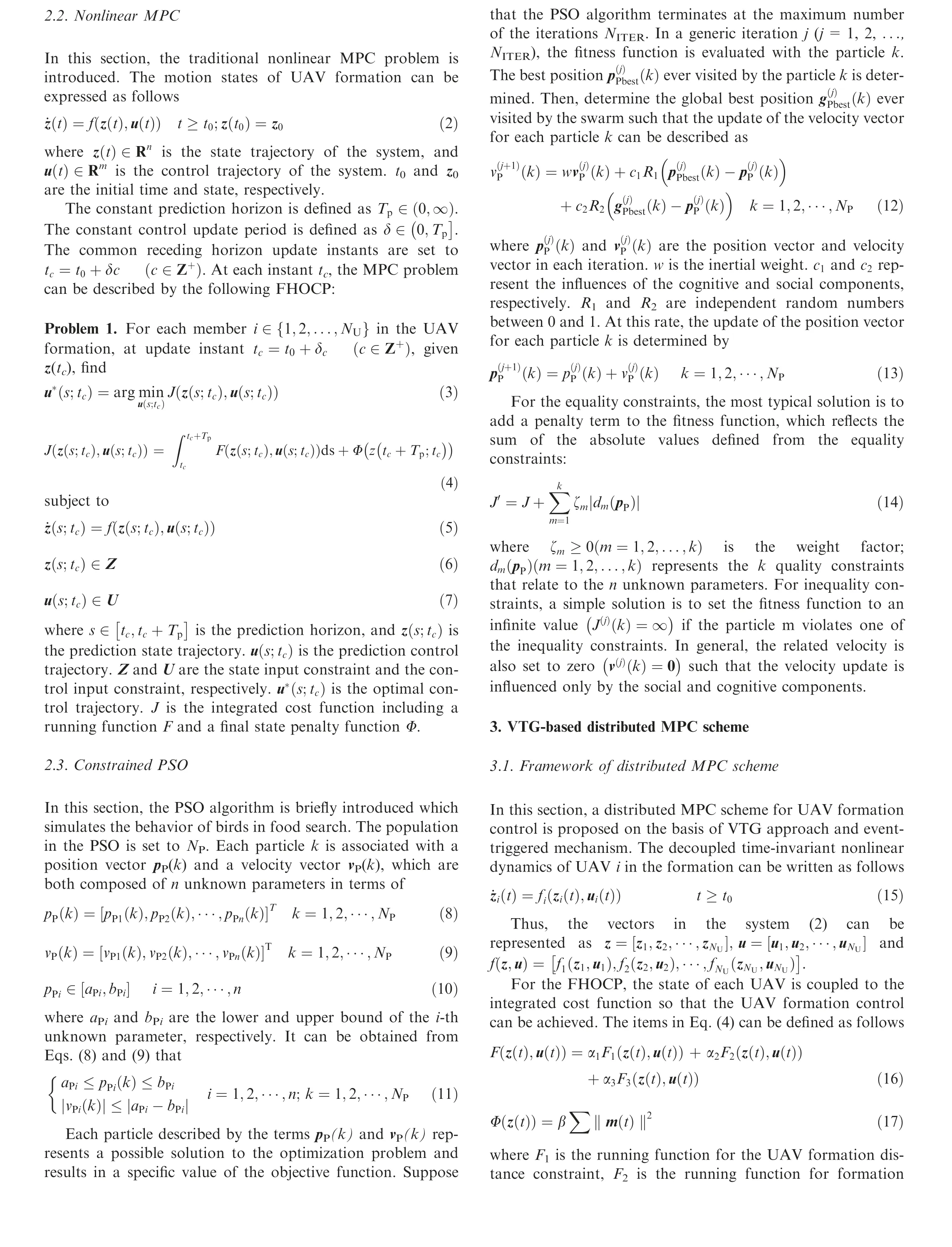
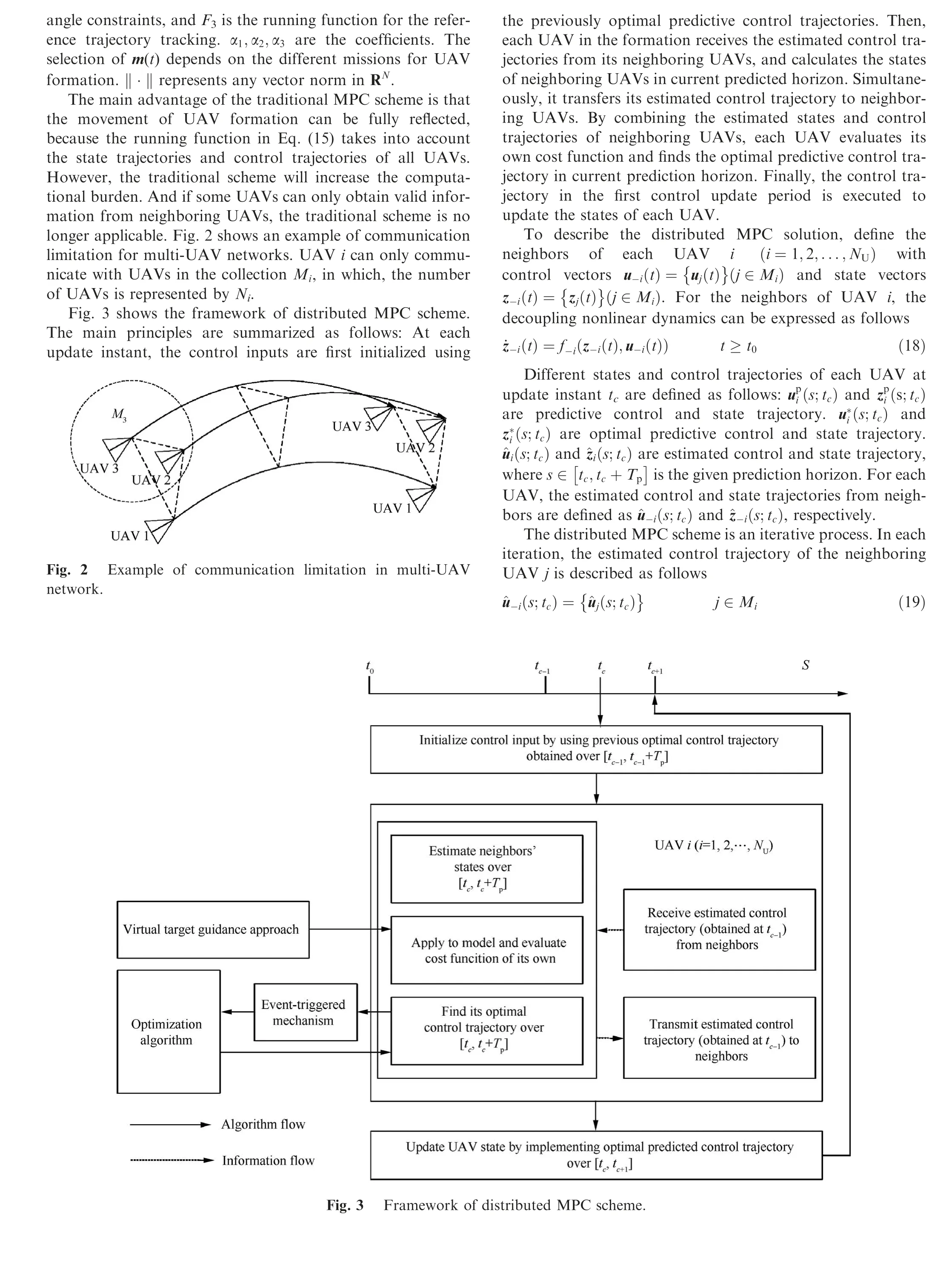
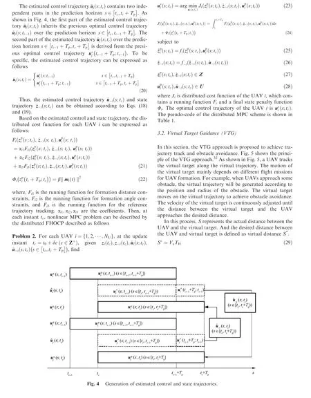
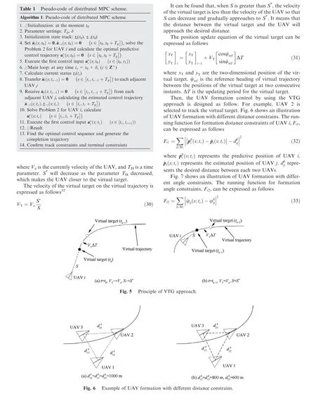
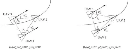
Fig. 7 Example of UAV formation with different angle constraints.
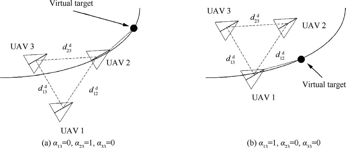
Fig. 8 Example of virtual target tracked by different UAVs in formation.
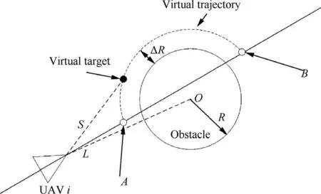
Fig. 9 Principle of VTG for obstacle avoidance.
Fig.8 shows an illustration of virtual target tracked by different UAV in the formation.The running function for the reference trajectory tracking, Fi3, can be written as follows

where pvirt(tc) represents the position of virtual target. As shown in Fig.8,αi3=1 is satisfied only when the UAV i tracks the virtual target.
In summary, the running function of each UAV i can be written as follows
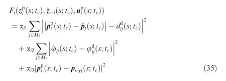
3.3. Obstacle avoidance
Obstacle avoidance can also be achieved by using the VTG approach. As show in Fig. 9, the circle obstacle is selected to show the principle of VTG approach for obstacle avoidance.The center coordinate of obstacle is (x0,y0). The radius of the obstacle is R.ΔR is the safe distance.The virtual trajectory is designed as an arc with the point O as the center and R + ΔR as the radius.The points A and B are selected as starting point and ending point of virtual trajectory during obstacle avoidance, respectively. These two points are the intersections the original virtual trajectory without obstacles and the circle with O as the center and R+ΔR as the radius. Thus, the new virtual trajectory for obstacle avoidance is generated between points A and B with the shape of arc.L is the distance between UAV and the center of obstacle.
In order to achieve obstacle avoidance, the velocity of the virtual target is designed on the basis of the relationship of R, ΔR and L, which is expressed as follows on the compromise between optimal performance and computational efficiency with respect to the distributed MPC scheme.

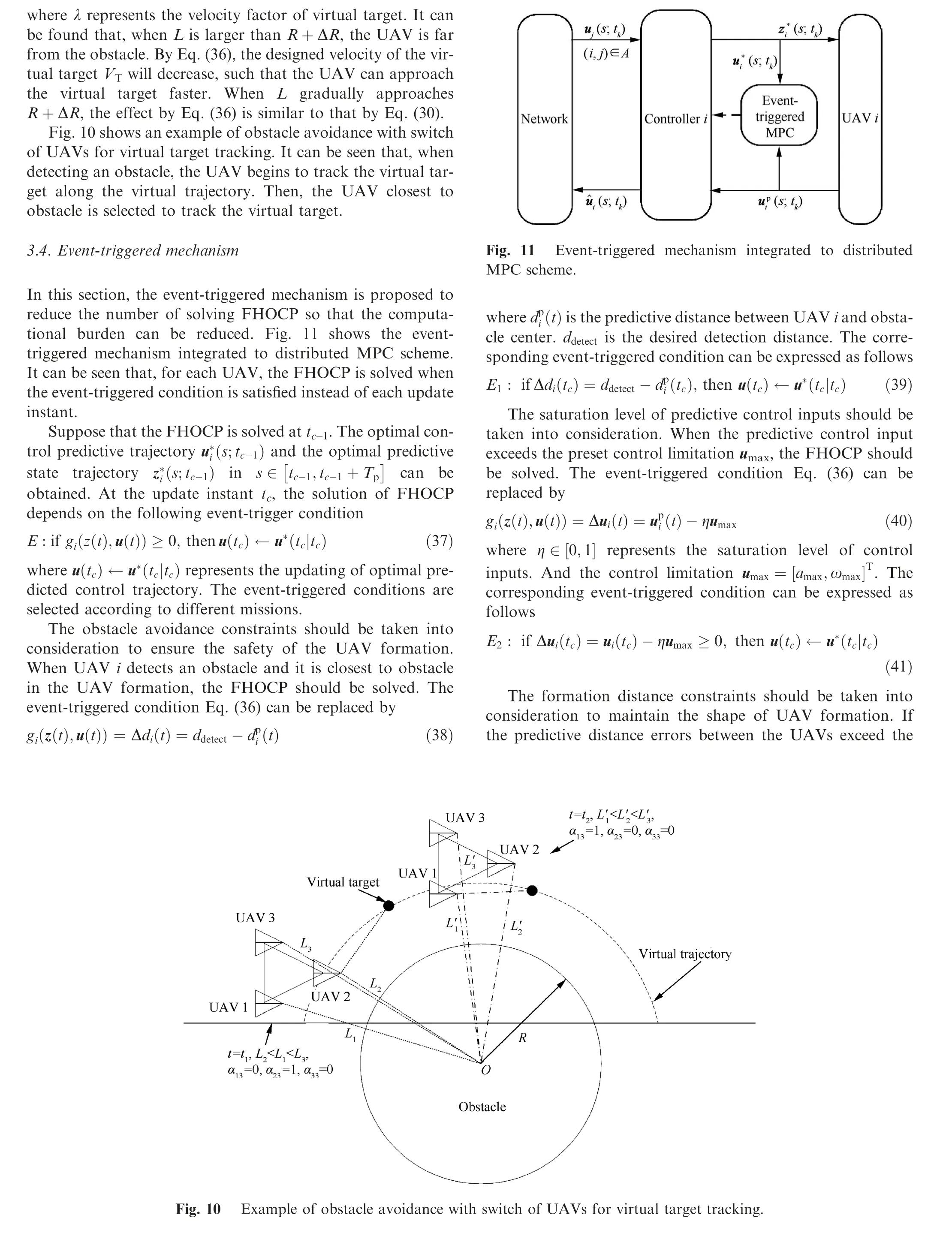
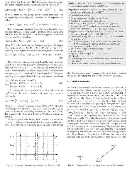

Table 3 Control limitations.

Table 4 Parameters in MPC.

Table 5 Parameters in PSO.
The contents of three groups of numerical simulations are given in Table 6, including the VTG-based distributed MPC scheme, VTG-based distributed MPC scheme with eventtriggered mechanism, and VTG-based distributed MPC scheme for obstacle avoidance. In the simulation results,UAV 1,UAV 2 and UAV 3 are represented in solid line,dash line and dash line, respectively.
4.1. Example I (VTG-based distributed MPC scheme)
In this example,numerical simulation is performed in order to test the effectiveness of the VTG-based distributed MPC scheme.The designed virtual trajectory of the UAV formation consists of three segments of straight lines and two segments of arcs.The angle constraints are set to φ12=45°and φ23=45°,respectively. The time parameter is set to TH=1 s when the UAV formation flies in straight lines, and TH=2 s in arcs.In this numerical simulation, UAV 2 is selected to track the virtual target. Table 7 shows the initial states of three UAVs.
Fig. 14 presents the formation trajectories of the group of UAVs. The three UAVs can maintain the desired formationshape and track the desired virtual trajectory. Fig. 15 shows the distances between each two UAVs in the formation. It can be found that the distances converge after about 19.5 s.
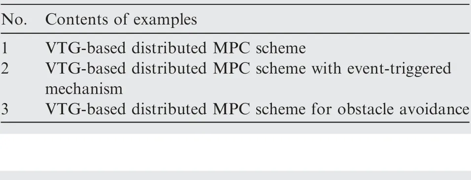
Table 6 Examples of numerical simulations.

Table 7 Initial states of three UAVs (Example I).
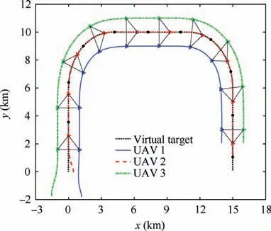
Fig. 14 Formation trajectories (Example I).
Fig. 16 presents the state and control trajectories of each UAV including the linear velocity, yaw angle, acceleration,and angular velocity. It can be seen that the linear velocity of each UAV is close to others when flying in straight lines.While in arcs, the linear velocity of UAV 3 is faster than that of UAV 1 in order to maintain the desired formation shape.In addition, the yaw angles of the three UAVs change synchronously. The accelerations and angular velocities are all within the control limitations. Fig. 17 shows the velocity and distance variables in the VTG approach. The velocity of the virtual target at each instant is represented by blue asterisk,and the velocity of the UAV that tracks the virtual target is represented by black cross. Similarly, the distance between the virtual target and the UAV at each instant is represented by blue asterisk, and the virtual distance is represented by black cross. It can be found that the actual distance S approaches the desired virtual distance S*in the process of tracking the virtual target. And eventually, the velocity of the virtual target, VT, also approaches the velocity of the UAV, Va.
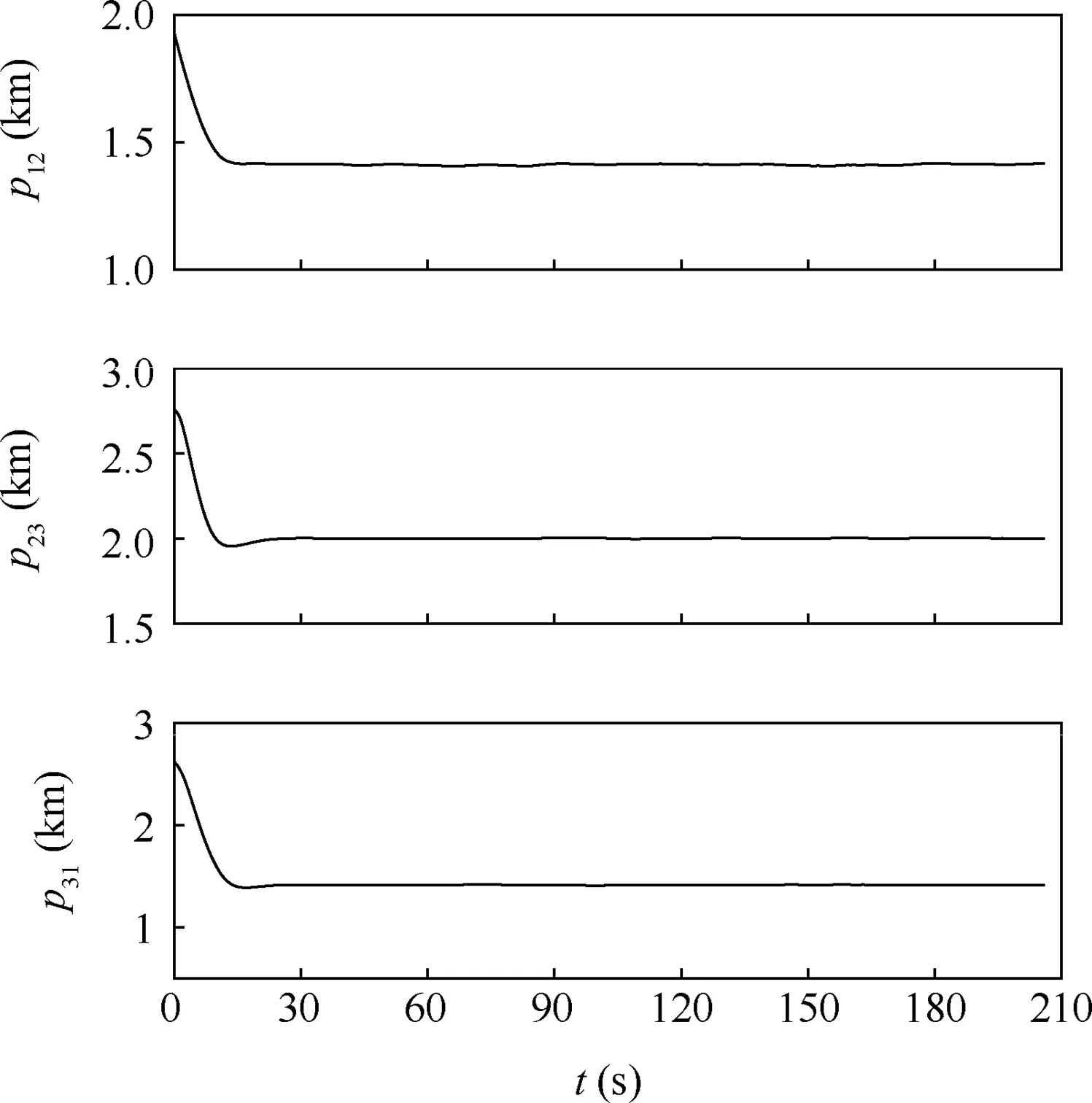
Fig. 15 Distances between each UAV (Example I).
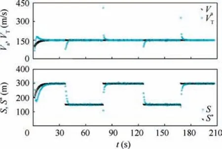
Fig. 17 Velocity and distance variables in VTG approach(Example I).
4.2. Example II (VTG-based distributed MPC scheme with event-triggered mechanism)
In this example, four cases of simulations for the VTG-based distributed MPC scheme with different event-triggered conditions are performed.The parameter settings of the simulations are shown in Table 8. In this example, UAV2 is selected to track the virtual target.Table 9 shows the initial states of three UAVs.

Table 9 Initial states of three UAVs (Example II).
4.2.1. VTG-based distributed MPC scheme with E2, E4, and E5as event-triggered conditions
In this part,two cases of simulations are performed to demonstrate the effectiveness of the proposed VTG-based distributed MPC scheme. Fig. 18 shows the flowchart of VTG-based distributed MPC scheme with E2, E4, and E5as event-triggered conditions. Table 9 shows the initial states of three UAVs.
Fig. 19 presents the formation trajectories of the group of UAVs.It can be seen that the three UAVs can form and maintain a desired formation shape and track the desired virtual trajectory in the two cases of simulations. The orientations of the two group of UAVs are different because different angle constraints are imposed in the two cases.Fig.20 shows the distances between each two UAVs in the formation. The distances converge after about 20 s and the differences between actual and desired distances are within 20 m.
Fig. 21 presents the state and control trajectories of each UAV including the linear velocity, yaw angle, acceleration,and angular velocity. Similar as the results in example 1, the linear velocity of each UAV is close to others when flying in straight lines, and the linear velocity of UAV 3 is faster than that of UAV 1 in arcs.The yaw angles of the three UAVs also change synchronously. The accelerations and angular velocities are all within the control limitations. In addition, it can be found that the control input at the previous update instant is often used without solving the FHOCP, because the eventtriggered condition is not satisfied at some update instants.
Fig. 22 shows the velocity and distance variables in the VTG approach. The actual distance approaches the desired virtual distance in the process of tracking the virtual target,and the velocity of the virtual target also approaches the velocity of the UAV. It can be found that, the convergence time of VTand S is about 14 s in each segment of trajectory in both two cases.
Fig. 23 shows the event-triggered instants of each UAV in the two cases.It can be seen that the FHOCP in the proposed VTG-based distributed MPC scheme is not solved at some update instants. The numbers of event-triggered instants of each UAV are shown in Table 10. With the event-triggered mechanism, the numbers of event-triggered instants in both the two cases are reduced to about 200,which are much smaller than those about 410 by using traditional MPC scheme.

Table 8 Parameters of VTG-based distributed MPC scheme with different event-triggered conditions.
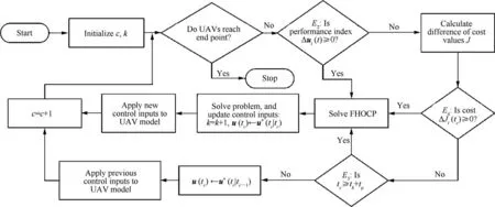
Fig. 18 Flowchart of VTG-based distributed MPC scheme with E2, E4, and E5 as event-triggered conditions.
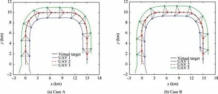
Fig. 19 Formation trajectories (Cases A and B).
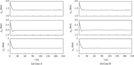
Fig. 20 Distances between each UAV (Cases A and B).
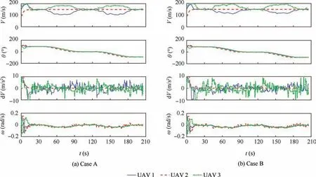
Fig. 21 State and control trajectories of each UAV (Cases A and B).
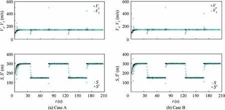
Fig. 22 Velocity and distance variables in VTG approach (Cases A and B).
4.2.2. VTG-based distributed MPC scheme with E2, E3, and E5as event-triggered conditions
In this part, anther two cases of simulations are performed to demonstrate the effectiveness of the proposed VTG-based distributed MPC scheme. The parameters used in cases C and D are also showned in Table 8. Fig. 24 shows the flowchart of VTG-based distributed MPC scheme with E2, E3, and E5as event-triggered conditions.
Fig. 25 shows the formation trajectories of the group of UAVs. It can be found that the three UAVs can form and maintain a desired formation shape and track the desired virtual trajectory in two cases of simulations. Fig. 26 shows the distances between each two UAVs in the formation. In both cases, the distances converge after about 21.5 s. In case C,the differences between actual and desired distances are within the given threshold, εp=30 m, which is smaller than those within the given threshold, εp=50 m, in case D. This is because the given distance error thresholds in two cases are different.Once the differences between predicted and desired distances reach the distance error thresholds, the FHOCP is solved to update the control inputs to reduce the differences.
Fig. 27 presents the state and control trajectories of each UAV including the linear velocity, yaw angle, acceleration,and angular velocity. Similar as the results in example 1, the linear velocities of each UAV are close to others when flying in straight lines,and the linear velocity of UAV 3 is faster than that of UAV 1 in arcs.The yaw angles of the three UAVs also change synchronously. The accelerations and angular velocities are all within the control limitations. In addition, it can be found that the control input at the previous update instant is used without solving the FHOCP, because the eventtriggered condition is not satisfied at some update instants.
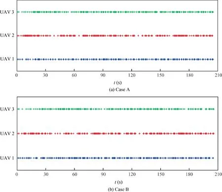
Fig. 23 Event-triggered instants of each UAV (Cases A and B).

Table 10 Numbers of event-triggered instants of each UAV(Cases A and B).
Fig.28 shows the velocity and distance variables in the VTG approach. The actual distance approaches the desired virtual distance in the process of tracking the virtual target, and the velocity of the virtual target also approaches the velocity of the UAV. It can be found that, the convergence time of VTand S is about 17 s in each segment of trajectory in both the two cases.
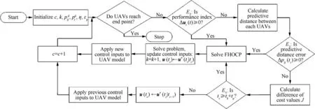
Fig. 24 Flowchart of VTG-based distributed MPC scheme with E2, E3, and E5 event-triggered conditions.
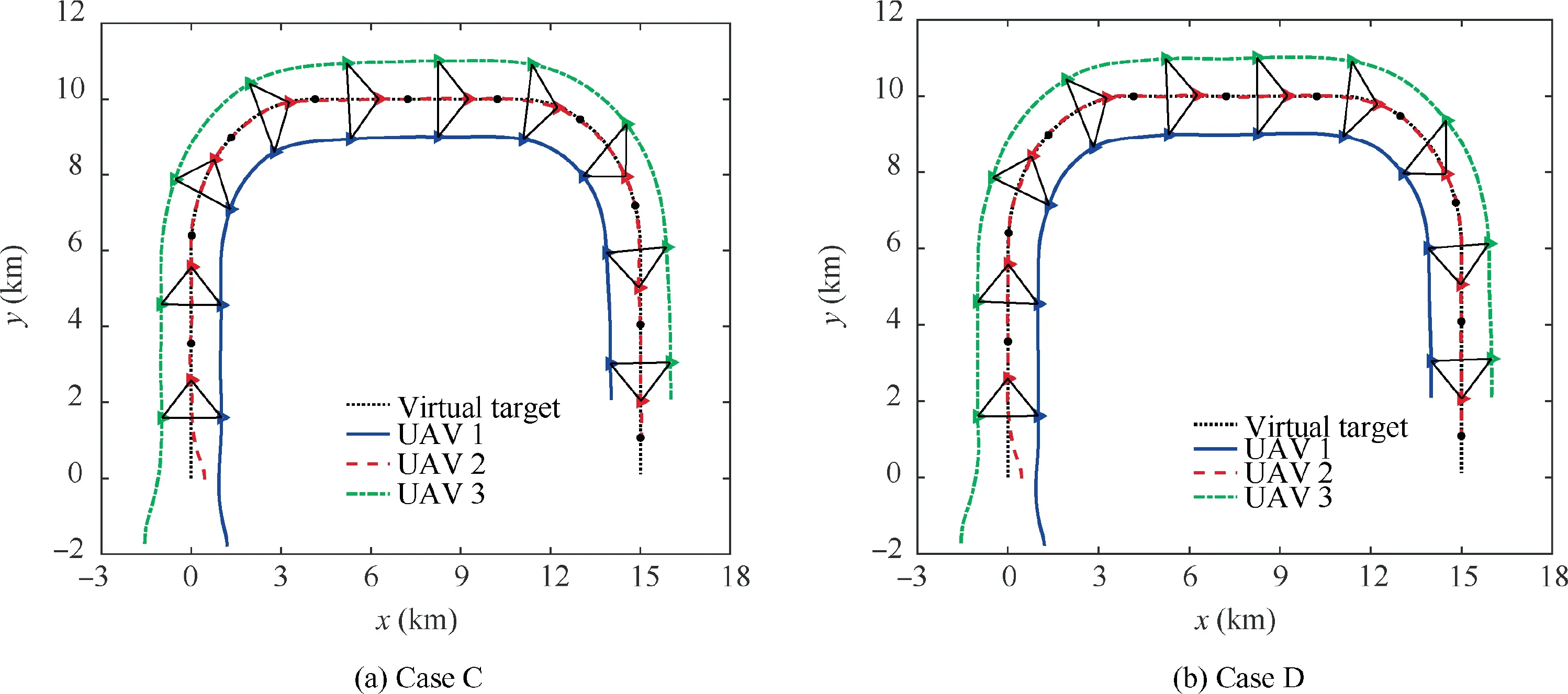
Fig. 25 Formation trajectories (Cases C and D).

Fig. 26 Distances between each UAV (Cases C and D).
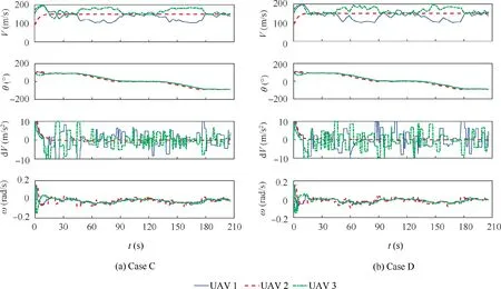
Fig. 27 State and control trajectories of each UAV (Cases C and D).
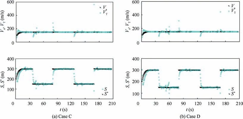
Fig. 28 Velocity and distance variables in VTG approach (Cases C and D).
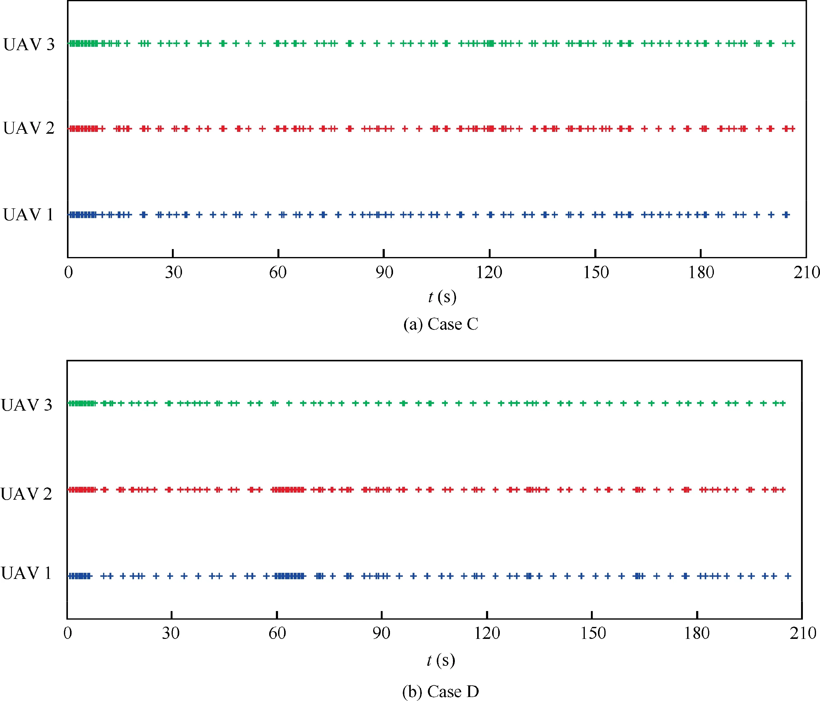
Fig. 29 Event-triggered instants of each UAV (Cases C and D).
Fig. 29 shows the event-triggered instants of each UAV in the two cases. It can be seen that, before about 10 s, the FHOCP is solved frequently. This is because the shape of the UAV formation is unformed, and the distance errors are larger than the given distance error threshold.The numbers of event-triggered instants of each UAV are shown in Table 11.With the event-triggered mechanism, the numbers of eventtriggered instants in both the two cases are reduced to about 100, which are much smaller than those about 400 by using traditional MPC scheme. In addition, the numbers of eventtriggered instants in case D are smaller than that in case C.The selection of distance error threshold depends on the compromise of computational efficiency and control performance. By the comparison of the simulation results betweenthe examples I and II, it can be seen that the VTG-based distributed MPC scheme with event-triggered mechanism can reduce number of solving FHOCP at the sacrifice of control performance.

Table 11 Numbers of event-triggered instants of each UAV(Cases C and D).

Table 12 Initial states of three UAVs (Example III).

Table 13 Parameter settings of obstacles (Example III).

Table 14 Parameters of VTG-based distributed MPC scheme for obstacle avoidance.
4.3. Example III (VTG-based distributed MPC scheme for obstacle avoidance)
In this example,the VTG-based distributed MPC scheme with obstacle avoidance is demonstrated. The designed virtual trajectory of the UAV formation consists of three segments of straight lines and two segments of arcs for obstacle avoidance.When flying in straight lines, UAV 2 tracks the virtual target.When a UAV detects an obstacle, the virtual target begins to move on the arc generated by the proposed VTG approach.During obstacle avoidance, the UAV which is closest to the obstacle tracks virtual target. Table 12 shows the initial states of three UAVs. Table 13 shows the parameter settings of the VTG-based distributed MPC scheme. Table 14 shows the parameter settings of the simulation in this example. Fig. 30 shows the flowchart of VTG-based distributed MPC scheme for obstacle avoidance.
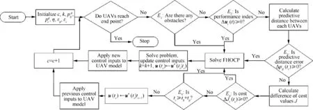
Fig. 30 Flowchart of VTG-based distributed MPC scheme for obstacle avoidance.
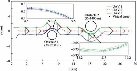
Fig. 31 Formation trajectories (Example III).
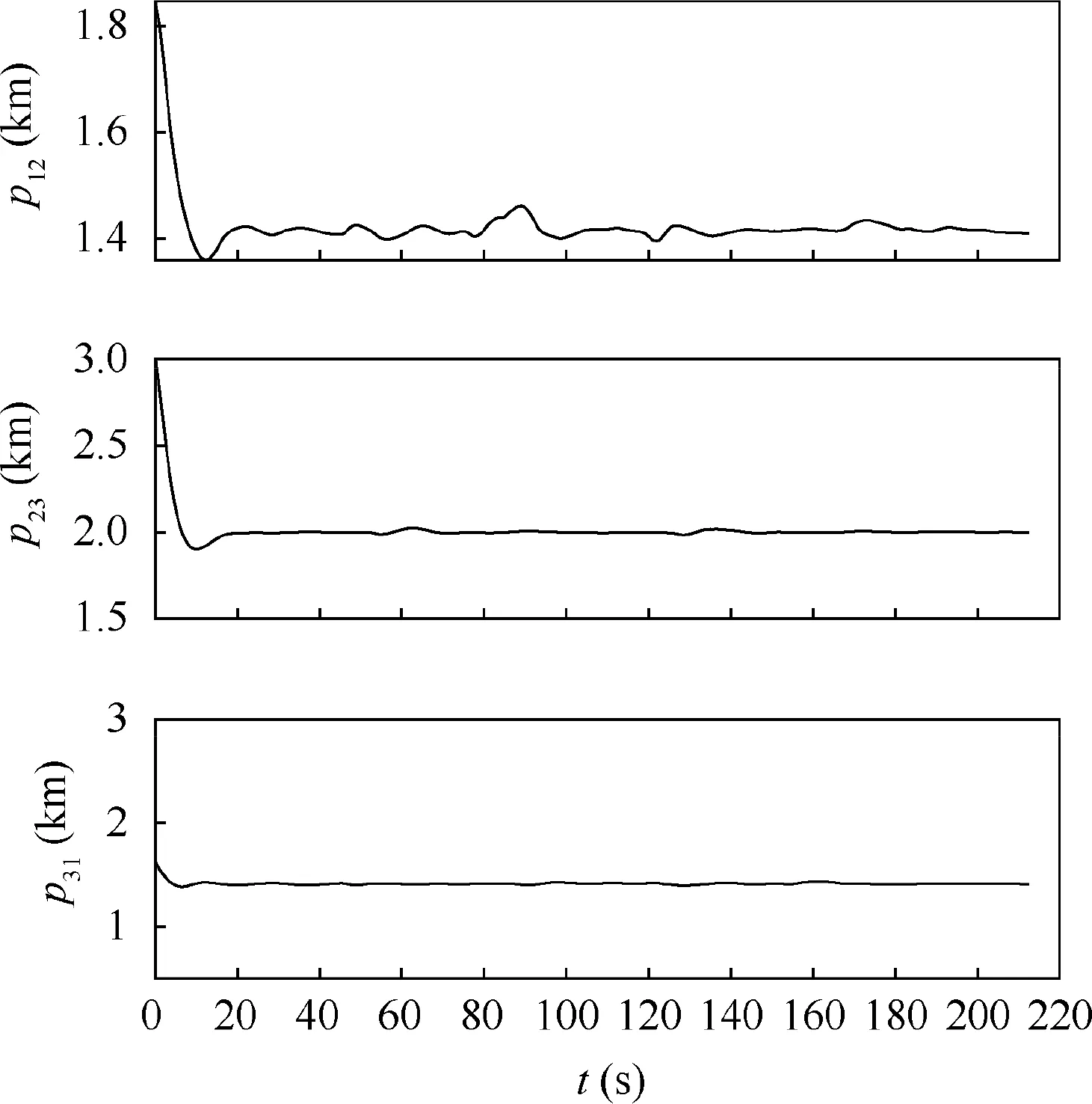
Fig. 32 Distances between each UAV (Example III).
Fig. 31 shows the formation trajectories of the group of UAVs. It can be found that the three UAVs can form and maintain a desired formation shape and accomplish obstacle avoidance. In the process of first obstacle avoidance, the UAV that tracks the virtual target switches from UAV 2 to UAV 1, and in the process of second obstacle avoidance, it switches from UAV 2 to UAV 3. Fig. 32 shows the distances between each two UAVs in the formation. It can be seen the distances converge after about 25 s. Fig. 33 presents the state and control trajectories of each UAV including the linear velocity, yaw angle, acceleration, and angular velocity. It can be seen that the linear velocity of each UAV is close to others.In addition, the yaw angles of the three UAVs change synchronously. The accelerations and angular velocities are all within the control limitations. It can be found that the accelerations and angular velocity of the other two UAVs in the formation change greatly in the processes of obstacle avoidance, because these two UAVs need to adjust the linear velocities and yaw angles to maintain the formation shape after the switch of UAV for tracking virtual target.
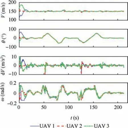
Fig. 33 State and control trajectories of each UAV (Example III).
Fig. 34 shows the velocity and distance variables in the VTG approach.When the group of three UAVs fly in straight lines, each variable in the VTG approach is represented in the same marks and colors as the previous examples. And in the process of obstacle avoidance,the color of marks representing actual distance and velocity of the virtual target is same as the color of the UAV that track the virtual target. It can be seen that the actual distance approaches the desired virtual distance in the process of tracking the virtual target,and the velocity of the virtual target also approaches the velocity of the UAV. In each straight segment of trajectory the convergence time of VTand S is within about 9 s.In each arc segment of trajectory,VTand S can also converge after 5 s.
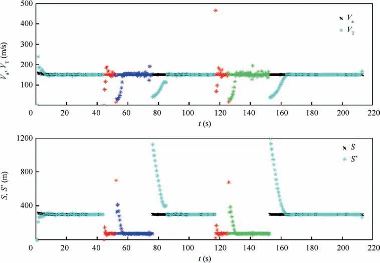
Fig. 34 Velocity and distance variables in VTG approach (Example III).
Fig. 35 shows the event-triggered instants of each UAV. It can be seen that the FHOCP is solved frequently in the process of obstacle avoidance. Fig. 36 shows the switch of UAV for tracking virtual target.It can be found that in the first obstacle avoidance process, the UAV that tracks the virtual target switches from UAV 2 to UAV 1, and in the second process,it switches from UAV 2 to UAV 3. The numbers of eventtriggered instants of each UAV are shown in Table 15. With the event-triggered mechanism, the number of event-triggered instants are reduced to about 280,which is smaller than about 420 by using traditional MPC scheme. It can be seen that the numbers of event-triggered instants by E3and E4are much larger than the numbers by other event-triggered conditions,which means that the solutions of FHOCP mainly depend on the large distance error and obstacle avoidance.
5. Conclusions
The VTG-based distributed MPC scheme for formation control of multiple UAVs is studied in this paper.The framework of distributed MPC scheme is developed for UAV formation.Each UAV only shares information with the neighbors and the obtained local FHOCP are solved by simple PSO algorithm. The VTG approach is developed and integrated into the distributed MPC scheme for trajectory tracking and obstacle avoidance. The numerical results show that one of the UAVs in the formation can track the virtual target along the virtual trajectory and the velocity of the virtual target is adaptively adjusted until the distance between the virtual target and the UAV approaches the desired value. An event-triggered mechanism is also proposed to reduce the computational burden for UAV formation control, which takes into consideration the predictive state errors as well as the convergence of cost function. The numerical results show that the number of the solutions of FHOCP can be reduced by using the proposed event-triggered mechanism. The future work will focus on the design of the complete three-dimensional formation control method and perform the flight test of UAV formation control to demonstrate the effectiveness of the proposed distributed MPC scheme.
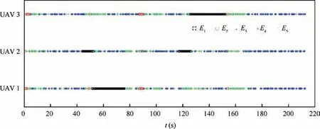
Fig. 35 Event-triggered instants of each UAV (Example III).

Fig. 36 Switch of UAV for tracking virtual target (Example III).

Table 15 Numbers of event-triggered instants of each UAV using different schemes.
Acknowledgements
This work was supported in part by the National Natural Science Foundation of China (No. 61803009), Fundamental Research Funds for the Central Universities, China (No.YWF-19-BJ-J-205), and Aeronautical Science Foundation of China (No. 20175851032).
 CHINESE JOURNAL OF AERONAUTICS2020年3期
- CHINESE JOURNAL OF AERONAUTICS的其它文章
- Experimental investigation on operating behaviors of loop heat pipe with thermoelectric cooler under acceleration conditions
- Investigation of hot jet on active control of oblique detonation waves
- Experimental study of rotor blades vibration and noise in multistage high pressure compressor and their relevance
- Unsteady wakes-secondary flow interactions in a high-lift low-pressure turbine cascade
- Effect of protrusion amount on gas ingestion of radial rim seal
- Optimization design of chiral hexagonal honeycombs with prescribed elastic properties under large deformation
