Experimental investigation on operating behaviors of loop heat pipe with thermoelectric cooler under acceleration conditions
Yongqi XIE, Xinyu LI, Sujun DONG,*, Hongxing ZHANG, Hongwei WU
a School of Aeronautic Science and Engineering, Beihang University, Beijing 100083, China
b Beijing Key Laboratory of Space Thermal Control Technology, China Academy of Space Technology, Beijing 100094, China
c School of Engineering and Computer Science, University of Hertfordshire, Hatfield AL10 9AB, United Kingdom
KEYWORDS Acceleration;Electronic cooling;Loop heat pipe;Operating performance;Thermoelectric cooler
Abstract An experimental study was carried out in this article to investigate the transient operating performance of a Dual Compensation Chamber Loop Heat Pipe(DCCLHP)with Thermoelectric Cooler (TEC) under acceleration conditions and ammonia was selected as the working fluid.For the purpose of comparison, experimental work was conducted under terrestrial gravity. Sensitivity analysis was performed to explore the effect of several control parameters such as the heat load, acceleration magnitude and TEC assist on the startup and operating performance of the DCCLHP. Experimental results indicate that the DCCLHP can get to a steady-state operation when the heat load changes from 25 W to 300 W under terrestrial gravity.While under acceleration conditions, the DCCLHP can work at a high operating temperature or even fail to operate, which shows the acceleration effect plays a significant impact on the loop operation.The TEC assist with power of 10 W can improve the operating performance and reduce the operating temperature for the case of small heat load and acceleration magnitude. When the acceleration exceeds 3g at large heat load, the effect of TEC assist on the operation at large heat load can be ignored.
1. Introduction
Loop Heat Pipes(LHPs)have been recognized as high efficient two-phase heat transfer devices,in which the working fluid circulation is driven by the capillary force derived from the wick and the heat is transferred by the latent heat of evaporation and condensation.1-3LHPs have attracted more and more attentions due to its advantages such as high efficiency, selfstarting, flexibility and long distance heat transport.3-5Nowadays,LHPs have been widely applied in the area of spacecraft thermal control and high heat flux electronics cooling.6,7
Although LHPs have been used successfully in aerospace thermal control, it should still be noted that typical single Compensation Chamber (CC) LHP cannot start up and operate properly when the evaporator location is higher than the compensation chamber under terrestrial gravity conditions.8This abnormal operation of LHP under the special condition had been confirmed by Chen et al.9and Ku et al.10. As is always the case,advanced military aircraft perform maneuvers to achieve tactical purpose of offence and defense. Thus, the airborne electronic devices are subjected to acceleration forces with different magnitudes and directions. It should be noted that, under acceleration condition, the wick of the single CC LHP cannot be infiltrated by the liquid working fluid at some installation orientations of LHP and the LHP more likely suffers operation failure.
Over the past two decades,much effort has been devoted to investigating the operating performance and structure design of the single CC LHP with cylindrical evaporator.11-14These works mainly focused on applications in aerospace thermal control and electronic cooling under terrestrial gravity. Quite few reported the startup and operation performance of the single CC LHP under acceleration conditions. Ku et al.15,16experimentally investigated the startup performance and temperature stability for an ammonia-steel stainless LHP subjected to variable accelerations. Their results showed that the LHP could start up for all test cases. The operating temperature oscillated as the acceleration varied from 1.2g to 4.8g.Fleming et al.17performed an experimental study on the operating performance of a titanium-water LHP at variable accelerations from 0 to 10g. It was found that dry-out conditions happened more readily at lower heat loads of 100 W to 400 W than that at higher heat loads of 500 W to 600 W.The transient performances of a titanium-water LHP subjected to steady periodic acceleration forces in the form of a sine wave were experimentally investigated by Yerkes et al.18. It was stated that the LHP could not operate properly for most of cases as the acceleration prior to heat load was applied.Later on, they further studied the performance of a titaniumwater LHP under phase-coupled heat load to an acceleration field.19It was demonstrated that the LHP failed to operate at phase angles of 0°, 180° and 270°.
In order to solve the problem that the wick will not be infiltrated due to the liquid storing in the CC below the evaporator in terrestrial gravity,a DCCLHP is used by arranging two CCs at both ends of the evaporator.It was firstly confirmed by Gerhart et al.20,21that the DCCLHP could successfully operate at different positions between the evaporator and CCs.Lin et al.22experimentally studied the operating performance of a DCCLHP at various orientations among the evaporator,CCs and condenser under terrestrial gravity. They found that the DCCLHP showed different temperature control behaviors and had a widely potential application in aircraft thermal management system. Bai et al.23performed an experimental study on startup behavior of a DCCLHP with insufficient fluid inventory. They observed that the DCCLHP could start up reliably even at a small heat load of 5 W, but the temperature shoot was rather high at times. In addition, they also studied the operating instability of a DCCLHP including temperature oscillation, temperature hysteresis and reverse flow. Their results showed that the orientation among the evaporator,CCs and condenser influence on the heat load range as the temperature hysteresis happened.24As an important visualization, Lin et al.25experimentally studied the operating performance of a DCCLHP at different relative orientations. They deemed that the initial vapor/liquid distribution in the entire loop could be impacted by the relative orientation.Experimental investigations on the steady-state and transient operating characteristics of an ammonia-steel stainless DCCLHP with insufficient inventory were performed by Xie et al.26,27. It was concluded that the DCCLHP could operate reliably at four different configurations under the acceleration up to 11g.
In summary, the operation principle and characteristics of the DCCLHP under terrestrial gravity have been reported by several previous studies.To the best knowledge of the authors,however,there are no detailed data available in the open literatures on the operating characteristics of the DCCLHP subjected to acceleration forces except for the previous study of the authors so far, especially on the operating characteristics of the DCCLHP with Thermoelectric Cooler (TEC) assist in acceleration fields.Therefore,the present work aims to address the transient operating characteristics of DCCLHP with and without TEC assist subjected to various acceleration forces and heat loads in a systematic manner. In the current study,both transient and steady-state characteristics of the DCCLHP are investigated under terrestrial gravity and acceleration conditions,different heat loads and acceleration magnitudes,with or without TEC are applied in the current work.
2. Experimental descriptions
2.1. Experimental setup
To experimentally investigate the operating behavior of a DCCLHP with TEC under acceleration, a newly test rig was set up in the present study in the Reliability and Environmental Engineering Laboratory at Beihang University. The schematic of the experimental setup is illustrated in Fig. 1. The test system mainly consists of the centrifuge and control subsystem, water cooling circulation subsystem, data acquisition and control subsystem, and test section.26,27
The centrifuge and control subsystem mainly includes a centrifuge in a circular pit, electric motor, transducer controller and control terminal. The centrifuge is driven by an electric motor which can provide up to 15g radial acceleration at the end of the rotational arm.A required radial acceleration was set and well controlled by a control terminal with an accuracy of ±5%. In the water cooling circulation subsystem, a recirculating thermostatic water tank was used to maintain the circulating water temperature constant. A gear pump driven by a variable-frequency driver sustained the water circulation in the loop. The mass flow rate of the cooling water was measured by a Coriolis force mass flow meter(DMF-1-2)with an accuracy of±0.5%.After flowing out of the cold plate condenser, the cooling water flows into a plate-type heat exchanger where it will be cooled to a lower temperature before return to the thermostatic water tank. The measuring signals from the mass flow meter and temperature transducers were recorded by a remote computer in the data acquisition and control subsystem. Two DC power supplies were used to supply for the thin-film heater and the TEC, respectively.
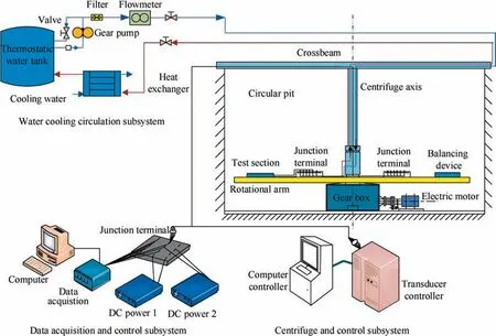
Fig. 1 Schematic diagram of test system.
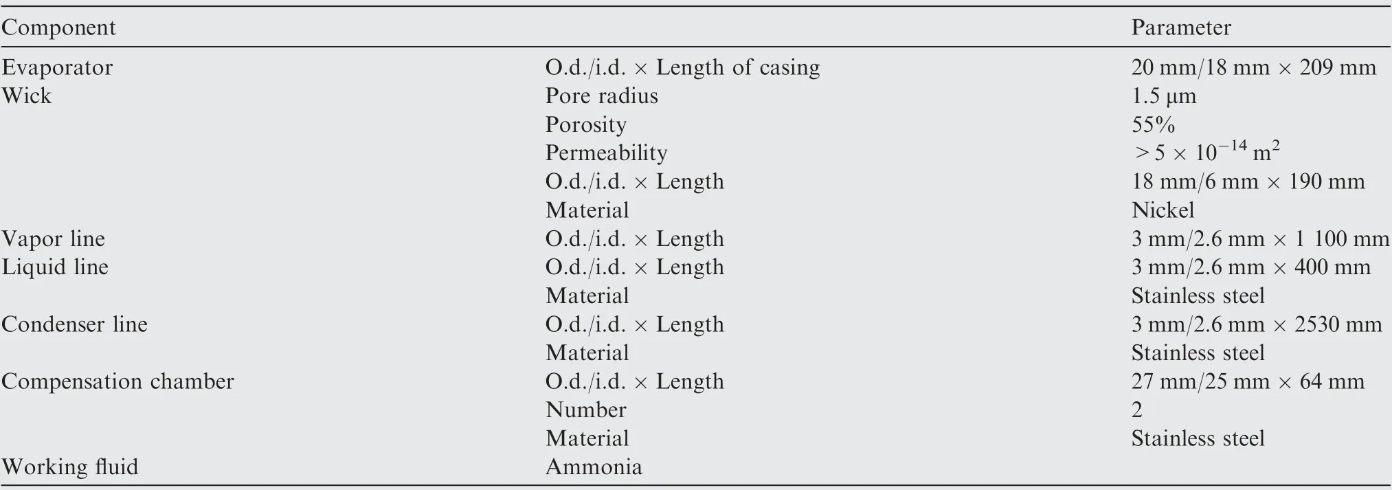
Table 1 Major design parameters of test DCCLH.
In the experiment,the stationary and rotational parts of the water loop tubes, signal wires and electrical wires for heating were linked up by the liquid collecting ring and the electric slip ring,respectively.The liquid collecting ring and the electric slip ring installed in the centrifuge axis were specially designed to ensure the flow and electric current working properly as the rotational arm was rotating during the test.
When the test section was fixed the rotational arm, The DCCLHP with outline size of 565 mm×520 mm×27 mm was subjected to a non-uniform acceleration field due to various distances from the loop to the centrifugal axis. The minimum and maximum values of the acceleration were 90% and 130% of the acceleration of the center over the test section,respectively.They could be achieved by regulating the rotating radius setting of the centrifuge to meet the requirement of GB/T2423.15.
2.2. Loop heat pipe
In the current study, a new ammonia-stainless steel DCCLHP with a bayonet was manufactured by the Chinese Academy of Space Technology.Table 1 lists the main design parameters of the DCCLHP. The DCCLHP was composed of the evaporator,vapor line,condenser,liquid line and two CCs.The nickel wick with a 1.5 μm pore radius was used in the evaporator with stainless steel casing.The bayonet extended to the middle point of the evaporator core.The outer diameter of all the transport lines was 3.0 mm. For the purpose of convenience, the CC passed through by the bayonet is called CC2 and the other one is called CC1.An internal structure of the evaporator and CCs are shown clearly in Fig. 2.
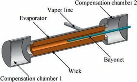
Fig. 2 Illustration of the internal structure of evaporator and CCs.
The condenser lines were welded to the copper heat expansion plate which was fixed to the surface of the cold plate by the bolts tightened. The thermal grease between the cold plate and heat expansion plate was utilized to reduce the contact resistance.All the components of the DCCLHP were wrapped with multilayer insulation materials to prevent heat transfer from the surroundings.For the purpose of thermal insulation,the DCCLHP was fixed in an enclosure filled with glass wool.
Two TECs with the dimensions of 30 mm×30 mm×4 mm were mounted on the CCs, respectively. The heating power was set to 10 W for each one. A thin-film electric resistance heater with the maximum capable of 400 W was attached on the outer surface of the evaporator to provide the heat load. Different heat inputs could be adjusted by regulating the output current and voltage of both DC powers in the range of 0-5 A and 0-250 V, respectively.
In order to monitor the temperature profiles along the entire loop, the ambient temperature as well as the inlet and outlet temperature of the cold plate, sixteen Resistance Temperature Detectors (RTDs) pt100 were attached on the outer wall of each component.Fig.3 presents the detailed allocation of these RTDs except for RTD14, RTD15 and RTD16, as RTD14 and RTD15 were used to measure the water temperature at the inlet and outlet of the cold plate, respectively,whereas RTD16 was used to monitor the ambient temperature.
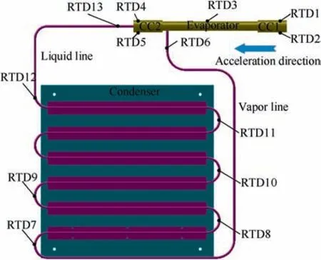
Fig. 3 Locations of RTDs on DCCLHP.
2.3. Experimental procedure
Prior to the real experiment, calibration was conducted for all the instruments. For RTD calibration, a standard RTD and thermostatic water bath were used. Two temperature ranges were divided according to the prospective operating temperature. One was the range of the ambient temperature and the circulating water temperature at the inlet and outlet of the cold plate, in which the corresponding RTDs were calibrated over the prospective range of 18-32°C with 2°C increments. The other was the range of the loop temperature,in which the thirteen RTDs located on the DCCLHP were calibrated over the whole range of 18-60°C in 2°C intervals.
The test section enclosure was installed horizontally at the required position along the rotational arm upon the requirement of the acceleration direction. In the present study, the direction of the acceleration force was parallel to the longitudinal axis of the evaporator and CCs, and pointed from CC1 to CC2, as shown in Fig. 3.
During the test, the heat load on the evaporator and the acceleration force were simultaneously applied. When the TEC assist enabled,the heat input on the CCs was also applied with the other loads. The heat input on each CC was 10 W.There were five main magnitudes(1g,2g,3g,4g,5g)and seven different heat loads (25 W, 80 W, 100 W, 150 W, 200 W,250 W, 300 W) applied to the evaporator. In all the test cases,the inlet temperature of the cold plate and the ambient temperature in the room were kept from 24°C to 26°C.
2.4. Error analysis
For a physical quantity Y, if it is a function of the measured variables x1, x2, ..., xi, its uncertainty can be expressed as follows28:

where δxirepresents the uncertainty of the ith variable measured.
In the current study, due to the effect of the data logger,electric wire, slip ring, junction terminal and RTD, the measured temperature accuracy was approximately ±0.5°C. The maximum uncertainty of the temperature was 2.8%.The maximum uncertainty of the voltage and current was 9.6% and 1.6%, respectively. Therefore, the maximum uncertainty of the heat load was 9.7%.
3. Results and discussion
3.1. Operating performance in terrestrial gravity
For the purpose of comparison, the operating performance of the DCCLHP with and without TEC assist under terrestrial gravity was investigated firstly at 25 W, 100 W, 200 W and 300 W.
Fig. 4 shows the temperature profiles along the DCCLHP with and without TEC assist at 25 W. From Fig. 4, it can be observed that the DCCLHP was able to start up and reached a steady state. With TEC assist, it took much shorter time to reach steady state and no superheat occurred during the startup. The temperature of RTD1, RTD2 and RTD5 was obviously lower than that of the other component as TEC assisted.
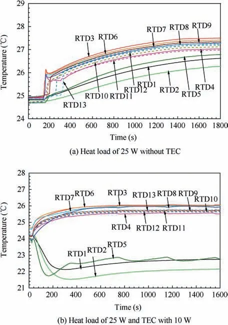
Fig. 4 Temperature profiles of each component at 25 W with and without TEC in gravity.
In Fig.4(a),as the heat load was applied on the evaporator,the RTD3 temperature increased immediately.Then the RTD6 temperature started to rise, which indicated that the vapor entered into the vapor line. It could also be seen that there was a very small superheat to generate vapor at 25 W. After starting up,the temperature of the evaporator,CC1,vapor line and condenser continue to increase. According to the RTD11 and RTD12 temperatures, the condenser was opened completely. There were vapor and liquid phase in both CC1 and CC2 in the light of their temperatures. At about 1600 s, a steady state was reached and the operating temperature was approximately 27.5°C.
In Fig. 4(b), as the heat load was applied, the evaporator temperature increased and the vapor occurred at once according to RTD3 and RTD6 temperature. The startup was deemed. The evaporator temperature kept 26.0°C after approximate 400 s. However, the temperatures of RTD1,RTD2 and RTD5 were apparently lower than those of the other points. Moreover, these temperatures were much lower than those in Fig. 4(a), which could be explained by the fact that the additional cooling of the TEC.For the energy balance of CCs,the heat leak from the evaporator to CCs was primarily balanced by the subcooling of returning liquid. As TEC assisted, the additional cooling was used to balance the heat leak.However,due to the small heat leak,the returning liquid was also cooled by the TEC. Thus, the temperature of RTD1,RTD2 and RTD5 significantly dropped, and RTD4 temperature was obviously higher than RTD5 temperature.The lower CC temperature led to a lower operating temperature.
For all the cases of 100 W, 200 W and 300 W, the DCCLHP with and without TEC assist could operate to a steady state. The steady-state operating temperature without TEC was 34.5°C, 37.0°C and 46.5°C. While it was 31.0°C,37.3°C and 44.9°C with TEC assist at 100 W, 200 W and 300 W, respectively. It was worthy of note that the temperatures of the evaporator, vapor line and condenser showed an obvious oscillation for the case of 100 W and without TEC assist. As a result, the DCCLHP could start up and reach a steady state for all cases under terrestrial gravity. When using TEC, the DCCLHP can reach a steady state within a short time and operate at a lower temperature in general. The temperatures of both two CCs were lower than those of the other component.
3.2. Operating performance under acceleration conditions
In order to facilitate the description of the load application,loading mode 1 and 2 are defined. Loading mode 1 represents that both the heat load on evaporator and acceleration force are applied simultaneously. While loading mode 2 indicates that the heat load on evaporator and acceleration force as well as TEC assist switch on at the same time.
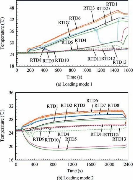
Fig. 5 Temperature profiles of DCCLHP at 5g and 25 W for both loading modes.
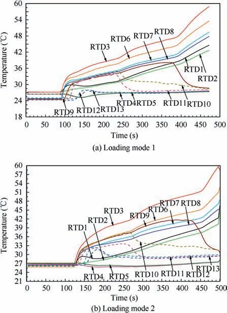
Fig. 6 Temperature profiles of DCCLHP at 5g and 300 W for both loading modes.
3.2.1. Influence of different heat loads
Fig.5 presents the temperature profiles of the DCCLHP at 5g and 25 W for loading mode 1 and 2. It could be clearly seen from Fig. 6 that there were obvious differences between both temperature profiles.For the loading mode 1,the temperatures of the evaporator,CC1 and vapor line tended to increase continuously.Finally,the loop did not reach a steady state within a given time. While the entire loop reached for the loading mode 2.
In Fig. 5(a), as the heat load was applied, the RTD3 temperature increased immediately. Then the RTD6 and RTD7 temperatures increased in turn,which indicated that the vapor entered the vapor line and reached the inlet of the condenser.The DCCLHP was deemed to start up. It was at approximate 360 s that both RTD7 and RTD8 began to oscillate with small amplitudes. Afterwards, the RTD8 temperature decreased to 25.3°C gradually and RTD7 rose with the increase of the evaporator temperature. This indicated that the vapor-liquid interface located somewhere between RTD7 and RTD8.However, it was after 1160 s that RTD7 also began to drop. The vapor-liquid interface returned to somewhere between RTD6 point and RTD7. At the same time, the temperatures of CC2 and RTD13 increased slowly. The reasons could be explained as follows: under a small heat load, the mass flow rate of the working fluid was small. The pressure head caused by the acceleration showed a significant impact on the movement of the working fluid.For example,CC2 was filled fully by the liquid while CC1 would be filled with most of the vapor.According to the temperature increase of CC2 and RTD13, the evaporation in the evaporator core probably occurred. The heat leak from the evaporator to CCs increased.The net pressure head resulted from the acceleration drove the vapor-liquid interface to return to the vapor line.Since the evaporator temperature continued to increase,the heat load and the acceleration force were removed at approximate 1460 s.The DCCLHP did not get to a steady state during the test.
As shown in Fig.5(b),when the heat load was applied,both RTD3 and RTD6 temperature increased immediately. This indicated that the vapor occurred and entered in the vapor line. After about 20 s, the vapor-liquid interface reached the RTD8 position referred by the RTD8 temperature increase.During the subsequent operation, the vapor-liquid interface moved to somewhere between RTD8 and RTD9.Additionally,it could be clearly seen that the temperatures of CC2 were lower than those of the other components. The reasons could be addressed as follows. The vapor-liquid distribution in the loop was changed by the acceleration force when the acceleration was applied.Much more liquid flooded into CC2 from the evaporator core and CC1. This successively caused the heat leak from the evaporator to CC2 decrease,but from the evaporator to CC1 increase. Thus the CC2 temperature showed a drop trend and the CC1 temperature reversed. Moreover, the TEC provided an additional cooling on both CCs.As a consequence, the CC2 temperature decreased below 20°C. However, the CC1 temperature RTD1 and RTD2 increased gradually. Finally, the entire loop reached a thermal equilibrium and the evaporator temperature was 30.8°C.
For the case of 300 W and 5g, the temperature profiles of the DCCLHP are depicted in Fig.6 under both loading modes.It could be found that the evaporator temperature ascended rapidly and continuously approached 60°C for both loading modes when applying the heat load. Due to safety issue, the experimental tests were terminated as the evaporator temperature was close to 60°C and obviously could not reach the steady state.
In Fig.6(a),along with the input of the heat load and acceleration force, the vapor-liquid distribution in the entire loop was changed and the liquid was pushed away from the direction of the acceleration force. Some liquid entered into the evaporator core and CC2 according to the change of RTD12, RTD13 and RTD4 temperature. Simultaneously,the vapor generated in the evaporator flowed into the condenser through the vapor line according to the temperature change of RTD6, RTD7 and RTD8. It could be considered that the DCCLHP started up at once as the loads were applied.The RTD12 temperature began to increase at about 120 s and reached the maximum value of 28.1°C at 152 s. Referring to the RTD11 temperature, the vapor-liquid interface was close to the outlet of the condenser,as shown in Fig.7.Noting that the vapor-liquid distribution estimated in Fig.7 was schematic according to the loop temperature.
Under this condition, a large heat load produced a large mass flow rate of the working fluid. An additional resistance was provided by the additional pressure head from the acceleration force due to the net length of the liquid column (H-h).This additional pressure head required a higher capillary pressure difference by the meniscus in the wick to balance the pressure loss.In accordance with the Clausis-Clapeyrong equation:a higher pressure difference between inside and outside wick needs a higher temperature difference. where hfgis the heat of vaporization of the working fluid, vfgis the difference between the vapor and liquid specific volumes, Δp is equal to the total pressure drop of the loop minus the pressure drop through the wick, ΔT is the temperature difference between the evaporator and CC.

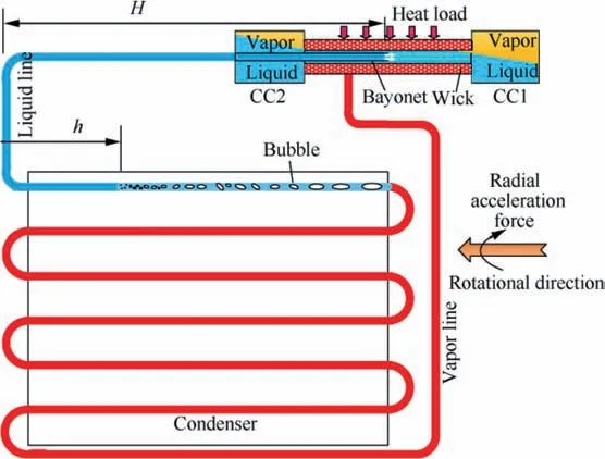
Fig. 7 Schematic illustration of additional pressure head by the acceleration.
Consequently, the evaporator temperature increased. The heat leak from the evaporator to CC1 increased, and then the CC1 temperature increased.Since the area of the condenser could not further enlarge, the vapor-liquid interface might be forced to move backwards in order to reduce the length of the liquid column. However, it would lead to decreasing the effective cooling area of the condenser. As a result, the interface moved further back and the RTD11, RTD10 and RTD9 temperature dropped successively at 224 s, 236 s and 372 s.Correspondingly,the cooling area continuously reduced.With the continuous increase of the evaporator temperature,a steady state could not be achieved finally. From Fig. 6(a), the evaporator temperature took about 400 s to be close to 60°C safety value.
As shown in Fig. 6(b), the temperature variations of the loop were similar to those presented in Fig. 6(a) except for the CC2 temperature.The reason leading to these temperature variations could be attributed to the above explanation.Because of the additional cooling of TEC, the CC2 temperature was lower than that of the other components.The evaporator temperature continuously went up to almost 60°C.
When the acceleration magnitude was 5g, the operating temperature versus heat load for the cases with and without TEC is presented in Fig. 8. It is noted that the steady state was not achieved for the case of 25 W and 80 W without TEC assist as well as for the case of 250 W and 300 W, where the maximum operating temperature was used in Fig. 8. It could be found that the operating temperature with TEC assist was lower than that without,as the heat load was smaller than 200 W. Although the steady state was arrived at 200 W, the operating temperature with and without TEC assist reached 56.6°C and 58.7°C, which was very close to the safety value.For the case without TEC, the steady-state operating temperature was 38.8°C, 43.9°C at 100 W and 150 W, respectively.For the case with TEC assist, the operating temperature was 30.8°C, 32.7°C, 37.0°C and 37.1°C at 25 W, 80 W, 100 W and 150 W, respectively.
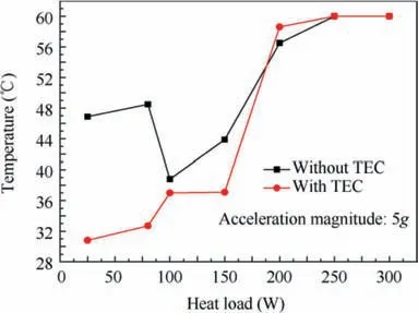
Fig. 8 Operating temperature versus heat load for cases with and without TEC assist.
Moreover, in comparison with the case under terrestrial gravity, it could be believed that the effect of the acceleration resulted in the failure operation of the DCCLHP at 25 W and 300 W,and increased the operating temperature at 100 W and 200 W.While as the TEC assist was used,the operation of the DCCLHP could be improved at small heat load,especially for 25 W and 80 W. A steady state could be achieved at 5g when applying TEC assist. However, it was almost not possible to improve the operation of the DCCLHP at large heat load of 250 W and 300 W.
3.2.2. Influence of different acceleration magnitudes
Based on the above discussions,it can be found that the acceleration has an important influence on the operation of the DCCLHP. Therefore, the following gives further discussion on the influence of different acceleration magnitudes at 300 W.
Fig.9 presents the temperature profiles of each component versus time at 1g and 300 W for both loading modes. It was worthy to mention that the temperature profiles of each component at 2g and 3g were similar to those shown in Fig. 9. It could be clearly seen from Fig. 9 that the steady state reached in both cases. The operating temperature for both loading modes was 45.0°C and 46.3°C, respectively. For the case without TEC assist, the CC2 temperature was close to the RTD12 and RTD13 temperature. While for the case with TEC assist, the CC2 temperature was smaller than that of the other components due to the TEC cooling.
In Fig.9(a),the DCCLHP started up rapidly with the input of the heat load and the acceleration.Because of a large initial temperature of the evaporator and CCs, the CC2 temperature showed an obvious drop by the cooling of returning liquid and then increased with the increase of the returning liquid.Referring to the RTD11 and RTD12 temperature, the vapor-liquid interface located at some point between RTD11 and RTD12 near the outlet of the condenser. The area of the condenser was used fully. Thus, most of the liquid returned to the CCs.Moreover, the acceleration effect caused much more liquid to be stored in CC2 but more vapor in CC1. This vaporliquid distribution contributed to decrease the heat leak from the evaporator to CCs.Due to the cooling of returning liquid,the RTD4 and RTD5 temperature was nearly the same and close to the temperature of the returning liquid. Because the 1g acceleration was small, the additional pressure head from the liquid column shown in Fig. 7 was also small. Consequently, the wick could provide sufficient capillary pressure difference to balance the pressure loss of the loop at its steady-state temperature. Thus the loop could reach a steady state.
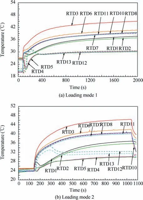
Fig.9 Temperature profiles of each component at 1g and 300 W for both loading modes.
In Fig.9(b),the DCCLHP could also start up rapidly.The CC2 temperature did not show apparent drop due to almost the same initial temperature for each component. It was due to the TEC cooling that the CC2 temperature was significantly lower than that of the liquid line according to the above analysis. It might be that the vapor-liquid interface rushed out of the condenser by the RTD12 and RTD13 temperature. It was about 347 s that the interface returned to somewhere between RTD11 and RTD12. A final operating temperature reached 46.3°C at a steady state. Compared to the case without TEC,it could be the reason that the heat load produced by the TEC was additionally applied on the evaporator and caused a consequent higher operation temperature.
When the acceleration magnitude increased to 4g, the DCCLHP could not reach a steady state.The evaporator temperature was close to 60°C under both conditions. The experimental tests were terminated for the purpose of safety. The operating temperature of the DCCLHP with and without TEC assist at 300 W under different acceleration conditions is shown in Fig.10.The operating temperature of 60°C represents that a steady sate was not achieved.For the case without TEC, the steady-state operating temperature was 45°C,45.2°C and 46.2°C at 1g,2g and 3g,respectively.For the case with TEC assist, the operating temperature was 46.3°C,46.9°C and 51.3°C, respectively.
It could be found from Fig. 10 that the operating temperature at 300 W for both loading modes increased with the increase of the acceleration magnitude. When the acceleration magnitude was beyond 4g, the DCCLHP could start up but could not reach a steady state. The operating temperature of the loop with TEC assist was higher than that without TEC assist for 1g,2g and 3g,which showed an opposite trend comparing to the cases of small heat loads. Especially at a large acceleration magnitude, the TEC could not drive the DCCLHP to operate to a steady state although it played a positive role on the operation. According to the above analyses,the reasons for this variation could be explained by the fact that the TEC cooling further reduced the effective cooling area of the condenser, and in turn enlarged the negative pressure head from the acceleration effect. The higher the acceleration magnitude, the higher the negative pressure head. This could lead to a greater heat leak and the CC1 temperature. Moreover, the additional heat load produced by the TEC increased the total heat load on the evaporator.Thus,the operating temperature increased until it was close to the safety value.
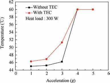
Fig. 10 Operating temperature versus acceleration at 300 W for both loading modes.
4. Conclusions
Experimental investigations of the transient operating performance of the stainless steel—ammonia DCCLHP with and without TEC assist were carried out under both terrestrial gravity and acceleration fields. The effect of different heat loads, acceleration magnitudes and with/without TEC on the operation was analyzed. The following main conclusions were made:
(1) The DCCLHP could start up and operate to a steady state at different heat loads under terrestrial gravity.Applying TEC assist could improve its operating and reduce its operating temperature.
(2) The acceleration effect significantly affected the DCCLHP operation under the given acceleration direction. It could cause a failure operation at a large acceleration magnitude. The TEC assist with 10 W could drive the loop to reach a steady state and reduce the operating temperature for small heat load. But it was almost not possible to improve the operation for large heat load.
(3) The primary cause of the operating performance under acceleration conditions was the change of the vaporliquid distribution by the acceleration effect. The additional pressure head from the acceleration enlarged the loop total pressure loss and operating temperature.
Acknowledgement
The authors acknowledge the financial supports from the Fundamental Research Funds for the Central Universities of China (YWF-14-HKXY-019).
 CHINESE JOURNAL OF AERONAUTICS2020年3期
- CHINESE JOURNAL OF AERONAUTICS的其它文章
- Investigation of hot jet on active control of oblique detonation waves
- Experimental study of rotor blades vibration and noise in multistage high pressure compressor and their relevance
- Unsteady wakes-secondary flow interactions in a high-lift low-pressure turbine cascade
- Effect of protrusion amount on gas ingestion of radial rim seal
- Optimization design of chiral hexagonal honeycombs with prescribed elastic properties under large deformation
- A global solution for robust parameter design of aeronautical electrical apparatus based oninteractions analysis and polynomial fitting
