Experimental study of rotor blades vibration and noise in multistage high pressure compressor and their relevance
Fengtong ZHAO, Xiaodong JING, Mingsui YANG, Deyou WANG,Yundong SHA, Xiaohi LUAN
a School of Energy and Power Engineering, Beihang University, Beijing 100191, China
b Liaoning Province Key Laboratory of Advanced Measurement And Test Technology of Aviation Propulsion Systems, Shenyang Aerospace University , Shenyang 110136, China
c Shenyang Engine Design and Research Institute, Aero Engine (Group) Corporation of China, Shenyang 110015, China
KEYWORDS Acoustic resonance;Blades vibration;Characteristic frequency;Multistage compressor;Source identification
Abstract Rotor blades fault of aeroengine compressor is mostly caused by mechanical and aerodynamic excitation. And the excitation factor of high intensity sound wave to rotor blades should not be ignored. Experimental researches are conducted on a multistage high pressure compressor.When high level vibration occurs on the first stage of rotor blades,the noise spectrum presents typical characteristic for discrete multi-tone in the compressor. The amplitude of blade vibration displacement and the sound pressure level of characteristic frequency noise increases and decreases simultaneously and reaches the maximum value at the same time. This frequency merely occur on a certain speed range and is locked in a specific range which presents no variation with the rotating speed. When high level vibration occurs on the first stage of rotor blades, the noise spectrum presents a sharp peak and the propagation state of the characteristic frequency is a helix structure in the compressor.It can be confirmed that acoustic resonance occurs in the multistage compressor.The acoustic resonance frequency and its side band frequencies are generated by modulation of a rotating noise source at the rotor speed which is the excitation source of the rotor blades vibration.
1. Introduction
Aeroengine compressor is a turbomachinery with high rotating speed,which usually works in complex environments with high temperature and high pressure. Flow instability is one of the most severe challenges in current aeroengine design and operation. It can induce violent blade vibration leading to structural damage,result in unacceptable noise level,and reduce the performance of aircraft engines and heavy-duty gas turbines.Unsteady flow instability occurs when the compressor is operated on the specific status. And this unsteady flow phenomenon not only has an important effect on the performance stability of compressor,but also may be an exciting source for the asynchronous vibration of rotor blades.1-3A great deal of progress on the well known phenomenon of rotating stall and rotating instability has been achieved, recent research focuses on acoustic resonance.4-6Rotating stall is seen as a rotating blockage due to flow separation in a few or several adjacent blade passages when the compression system is approaching the flow instability limit. Rotating flow instability already may occur in the stable operating range of a compressor, and appears as a significant amplitude increase in the pressure frequency spectra at the casing within a broad frequency band below the blade passing frequency (BPF) and above the rotor rotational frequency. Several discrete pressure peaks with almost constant spacing are usually superimposed on the frequency hump.7,8The similarity of the wall pressure signatures of completely different machines was accounted by Kameier7,9and Baumgartner et al.10Close to the half of the blade passing frequency, a hump occurred that comprised sum and difference frequencies. The high pressure compressor had blade vibration problems in this operating range.The lowpressure compressor generated high sound pressure levels with a strong tonal component. In order to demonstrate blades vibration, Haukap investigated the low-pressure compressor under these aerodynamic conditions with unrealistically smooth blades.11A tonal aerodynamic noise generator was found in a simple test configuration that emitted sound spectra similar to the fan or blower tip clearance noise.12With a focus on noise generation and noise amplitude amplification, Winkler investigated the cylinder-plate configuration.13The observation of flow-induced vibration with the configuration resulted in an extensive investigation of oscillation effects.14,15
While acoustic resonance causes a high and narrow pressure peak at several discrete resonance frequencies, which are not necessarily integer multiples of the shaft frequency.Acoustic resonance may produce significant acoustical excitation in aircraft engines when the engine is running at off-design conditions.In extreme cases,the structural integrity could be seriously endangered by large-amplitude acoustic pressure fluctuations. The measurement of acoustic resonance was firstly conducted in a low speed single stage compressor.16Sound omitted from the compressor at a sequence of frequencies was recorded and analyzed, which were due to acoustic resonances excited by periodic wakes shed from rotor blades.The mode of the resonance could comprise an integral number of waves round the annulus. And those discrete frequencies were associated with acoustic resonance. Systematic measurements of acoustic resonance was presented in a low-speed four-stage compressor and several acoustic modes at equal frequency interval were identified at the same time.17The dominating circumferential mode of excited acoustic pressure with a helical structure was cut-off in the compressor,which implied that the energy of acoustic waves was trapped in the circumferential direction. It also indicated that the measured acoustic frequencies were independent of the axial length of the duct.The amplitude of acoustic wave varied considerably in the pitchwise direction with respect to the variation in the spanwise direction.
When non-synchronous vibrations occurred in the compressor,unsteady pressure was also measured on the compressor casing at numerous axial and circumferential locations.18The dominate frequencies of unsteady pressure were related to blade passing.Blades excitation was explained as a 35 nodal diameter excitation rotating at 52% of rotational speed with respect to the rotor,or a 24 nodal diameter excitation rotating at 31%of rotor speed.Specifically,those resonant frequencies were measured in the non-rotating reference frame which were Doppler shifted from those seen in the rotating reference frame. The acoustic resonance was presented in a four stage axial compressor at the University of Hannover.19The compressor with controlled diffusion airfoils was operated at the Institute of Turbomachinery and Fluid Dynamics. It was found that the pressure signal was dominated by the BPF until the static pressure ratio reached the maximum value at 84.2%throttling position. Afterward, although the operating point was just beyond the design point and still far away from the stall limit, a new frequency component of about five times rotor rotational frequency starts to rise at a specific flow status,and its higher harmonics and beat frequencies with the BPF were also detected.It was verified that only acoustic resonance fitted the measured phenomenon. As an abnormal phenomenon under specific operating conditions in compressor,acoustic resonance has been widely known. However, there were no detailed research to expound the occurrence process of acoustic resonance in a real compressor. In particularly,when structural parts vibration and acoustic resonance synchronously occur in compressor, the relevance analysis are little mentioned.
In conclusion, nowadays the mechanism of acoustic resonance in compressor remain unclear. The effect of unsteady flow on the resonant acoustic field,the relevance between rotor blades vibration and acoustic resonance source still need to be explored.The frequency and the location of the source are still under discussion. Thus, there is not yet an effective design guideline on acoustic resonance for aeroengine. It is the lack of such a capacity that motivated the authors to carry out an experiment to capture the particular phenomena of acoustic resonance in the multistage compressor. To the best of the authors’ knowledge, this is the first attempt in open literature to experimentally investigate the resonant frequency in a real multistage high speed compressor. The characteristic noise occurs in the multistage compressor simultaneously with high level vibration on the first stage of rotor blades. This noise source position is identified at the first stage of rotor. The relevance between rotor blades vibration and acoustic resonance is established at different adjustment condition of the compressor.And the source mechanism of blades vibration is dissected which can provide directed criterion for rotor blades fracture.
2. Experimental facility
2.1. Testing rig
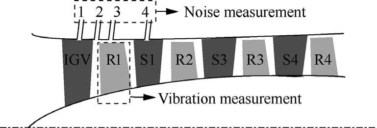
Fig. 1 General layout of multistage compressor.
The experimental test facility used in the present investigation consists of a multistage high speed compressor which is high pressure part of a core aeroengine along with the associated components and instruments. The general layout of the multistage compressor in the present investigation is shown in Fig. 1. The compressor is composed of inlet guide vanes(IGV),the first stage of rotor blades(R1),the first stage of stators (S1) and so on. The deflected angle of IGV and the first three stage stators can be adjusted to get various of inlet flow mass. The experiment is operated on the compressor working together curve to simulate the real operative condition of the matched aeroengine.These parameters including the vibration of rotor blades, the casing pressure and the rotor speed are monitored synchronously. The vibration status of R1 is monitored.Three mounting holes along circumferential position of R1 are selected for blades vibration measurement (see Fig. 2).There four testing positions for the casing pressure along the same circumferential direction and the different axial direction positions in the compressor. Position 1 (IGV) is the clearance of IGV.Position 2(IGV/R1)is the clearance between IGV and R1.Position 3(R1)is directly above R1.Position 4(S1)is the clearance of S1.
2.2. Blades vibration measurement system
It is a arduous work to measure blade vibration under rotating status. Because of the complex structure, conventional strain measurement method is difficult to be used in the rotating machinery testing. Therefore, a novel non-contact fiber optic vibration measurement technology is chosen.20The fiber optic vibration measurement system is composed of fiber optic sensor, photoelectric transducer, preprocessor, and blade vibration data acquisition and analysis software (see Fig. 3). The principle of the system is essentially to conduct intermittent measurement of the relative displacement of blades end. The original vibration process of blades is restored according to the measured intermittent value. And then, the parameters of the entire vibration process of blades are analyzed.In this testing, three fiber optic sensors are installed at the designated position at the casing above R1, and the positioning reference sensor is installed on the rotor. The time interval between the pulse measured by the tip amplitude sensor and the rotational speed pulse is calculated.When blades vibrate,the tip of blades deviates along the rotation direction, and the time to the sensor changes. Thus, the vibration parameters of rotor blades such as amplitude phase and frequency are obtained.
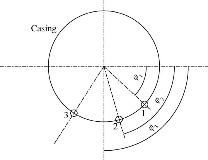
Fig. 2 Rotor blades vibration measurement positions.

Fig. 3 Rotor blades vibration measurement system.
2.3. Noise measurement system
This experimental multistage compressor is used for higher thrust high-bypass turbofan engines. In the compressor, the static pressure is up to 4 MPa, the temperature is about 270°F, and high intensity sound wave is about 170 dB with a broad range 50-12 kHz.Therefore,a noise measurement system is adopted for the casing pressure testing. It is essentially an acoustic waveguide system. A quarter inch condenser microphone is internally installed in the waveguide system.One end of the system is connected to a semi-infinite tube which applied to avoid the acoustic wave reflection in the system, and another end is connected to the compressor with the pipe which installed flush with inner surface of the connotation. The noise measurement system connection diagram is presented in Fig. 4.
The static calibration of the waveguide system is implemented by the pistonphone with 250 Hz/124 dB. The digital closed-loop acoustic calibration system is used to calibrate the dynamic characteristics of the waveguide system. The acoustic calibration system connection diagram is presented in Fig. 5. The frequency response data of various length pipe at different frequencies are obtained through the calibration system. And acoustic attenuation characteristic curves are plotted in Fig. 6.
3. Experiment results
3.1. Results of rotor blades vibration
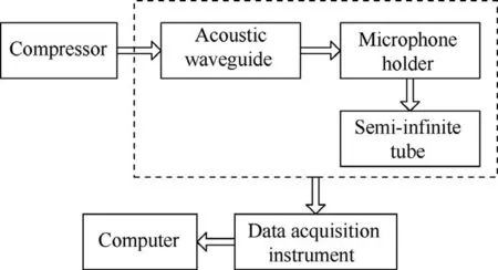
Fig. 4 Connection diagram of noise measurement system.
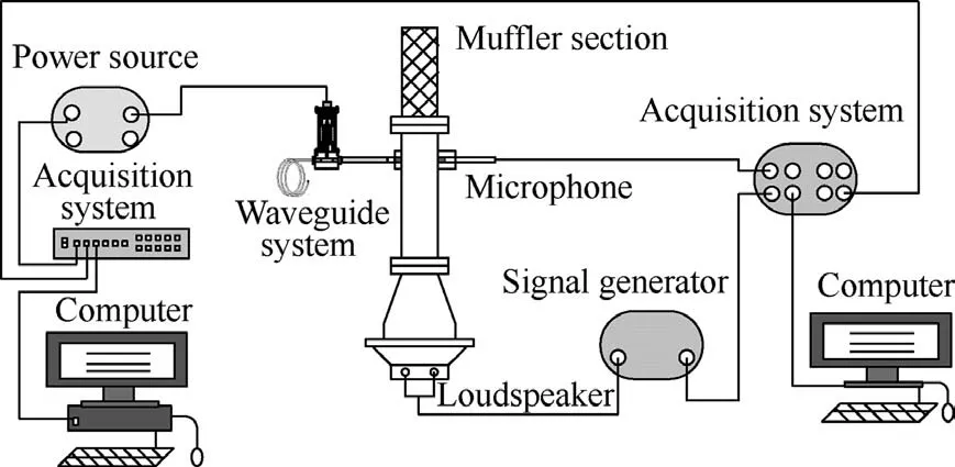
Fig. 5 Digital closed loop acoustic calibration system.
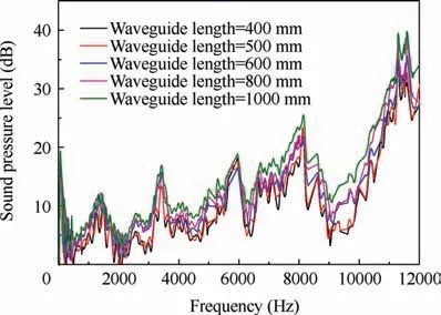
Fig. 6 Acoustic attenuation characteristic curves.
When the compressor is operated at various preset deflected angle for IGV and the first three stage stators, the vibration of the first stage of rotor blades is monitored at different rotor speed. The vibration displacement of the first stage of rotor blades is plotted in Fig. 7 all over the speed range. The pink line and the blue line represent the changing trend of rotor speed and rotor blades vibration displacement respectively.During the testing, the abnormal vibration of the first stage of rotor blades occurs in the speed range about 9480-10,560 r/min. Especially, when rotating speed reaches around 9960 r/min, the amplitude of the first stage of rotor blades vibration increases sharply.
3.2. Results of noise
During the testing, noise in the compressor is obtained with rotor baldes vibration synchronously. When high level vibration occurs on the first stage of rotor blades, the timedomain wave of noise is transformed into frequency spectrum by Fast Fourier Transform.It is shown in Fig.8.The noise frequency spectrum with special frequency structure measured at different testing positions is obtained in a pre-arranged structure adjustment and specific rotating speed. The noise spectrum presents typical characteristic for discrete multi-tone when high level vibration occurs on the first stage of rotor blades. Of all these frequencies, 6285 Hz is the blade passing frequency of the first stage of rotor blades. And 1402 Hz is a special characteristic frequency with the highest peak value.That means this characteristic frequency is the dominant ingredient in the frequency spectrum.
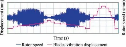
Fig. 7 Vibration displacement of rotor blades at different rotating speed.
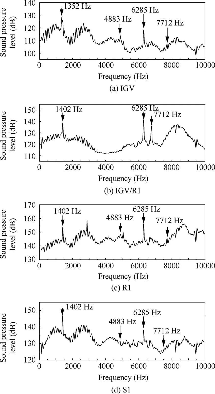
Fig. 8 Characteristic frequency spectrum at different measurement positions.
3.3. Relevance between noise and blades vibration
As shown above, when high level vibration occurs on the first stage of rotor blades, noise spectrum with characteristic frequency presents in the compressor synchronously. Therefore,corresponding relation between the internal noise and rotor blades vibration at different structure adjustment condition of the compressor is accounted in Fig. 9.It is found that once high level vibration of rotor blades occurs, the characteristic frequency noise measured directly above rotor blades appears simultaneously. The amplitude of rotor blades vibration displacement and the sound pressure level(SPL)of characteristic frequency noise increases and decreases simultaneously, and reaches the maximum value at the same time. So the source of the characteristic frequency noise directly concerned with the vibration of the first stage of rotor blades. And the characteristic frequency noise may be used as a criterion for rotor blades vibration in this status. However, the coupling mechanism between noise and vibration can not be confirmed.And this will be revealed bellow.
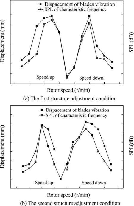
Fig. 9 Relevance between noise and blades vibration.
4. Analysis of acoustic resonance
4.1. Evolution rhythm of noise
In order to acquire the correlation between characteristic frequencies and the rotor speed,noise frequency spectrum is analyzed at different rotating speed. In a specific structural adjustment condition, the rotating speed of the compressor is pushed up from 9480 r/min to 10560 r/min and pulled down from 10560 r/min to 9480 r/min,the evolution rhythm of characteristic frequencies is shown in Fig. 10. Combining the first stage of rotor blades vibration,the amplitude of characteristic frequency 1402 Hz will synchronously increase with the sharp vibration of the rotor blades.And this characteristic frequency merely occur on the specific speed range, and has the association with structure adjustment of the compressor.As shown in Fig. 11, when acoustic resonance occurs in the compressor, fbis acoustic resonance frequency, fais the range of locked frequency.The characteristic frequency will be locked in a specific range which presents no variation with the rotating speed.It is considered the flow state in the compressor plays an important role on the cause of the characteristic frequency. This point should be paid more attention in the design and development of aeroengine.
4.2. Noise source identification
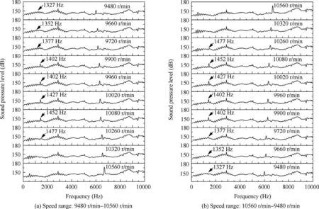
Fig. 10 Evolution rhythm of noise spectrum at different rotating speed.
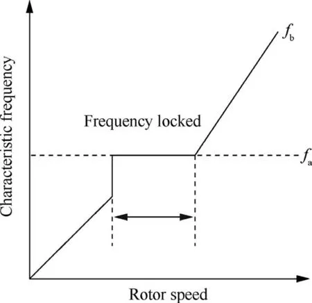
Fig. 11 Locked-in of characteristic frequency.
As mentioned above, the noise signal in the compressor presents the characteristics of multiple discrete pure tone in the specific structural adjustment state and rotating speed range.In particularly, the component of characteristic frequency 1402 Hz is also associated with the vibration of the first stage of rotors blades in the compressor.The sound pressure level of this frequency component will be analyzed to obtain its energy amplitude level at different status.Due to the high level vibration occurs on the first stage of rotor blades, the noise measured above the first stage of rotor blades is taken as a demonstration in the analysis of the SPL. During the testing,the rotating speed of the compressor is pushed up from 9420 r/min to 10560 r/min (see Fig. 12(a)) and pulled down from 10560 r/min to 9420 r/min (see Fig. 12(b)), rotor blades experience great level vibration at the specific speed range about 9840-10200 r/min. Through the whole process, the evolution of the SPL at 1402 Hz component is shown in Fig.12.It is found that the amplitude of the SPL at this frequency increases dramatically within that specific rotating speed range, meanwhile the magnitude of rotor blades vibration increases simultaneously.
Furthermore, the SPL along the axial distribution at 1402 Hz component in the compressor is compared and analyzed.The amplitude of the SPL at this frequency for different measured positions is shown in Fig. 13 when the abnormal vibration of rotor blades occurs. It can be found that the amplitude of the SPL at this frequency is relatively maximum at the testing position near the first stage of rotor blades. This indicates that the noise source of 1402 Hz component should be located near the first stage of high pressure rotor blades,which also mean that there is a strong coupling between sound waves and rotor blades.These analyses will be direct reference value to the analysis of abnormal noise source and the vibration mechanism of rotor blades.
4.3. Noise source propagation characteristics
Corresponding to high level rotor blades vibration in the compressor, noise signals at four testing positions are analyzed through cross-spectrum analysis.And the propagation regularity of the characteristic frequency 1402 Hz is expounded by its phase relationship at different testing positions.The phase difference results of the characteristic frequency at different testing positions are shown in Table 1. For example -115° is expressed as the phase of the characteristic frequency 1402 Hz at IGV is ahead of the phase at IGV/R1 about 115°, which indicates that the characteristic frequency noise propagates from IGV/R1 to IGV, and similar to others.
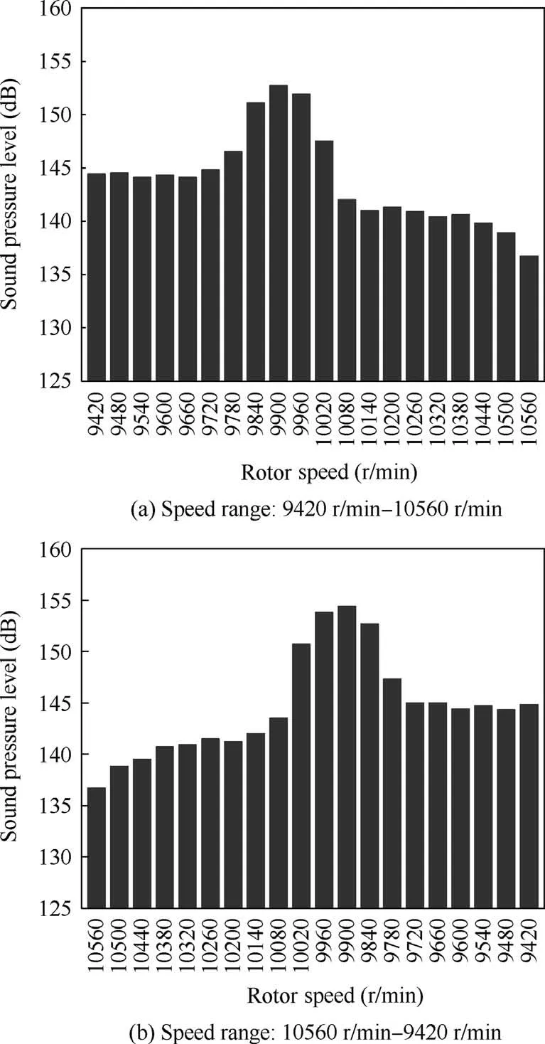
Fig. 12 Sound pressure level at different rotor speed.
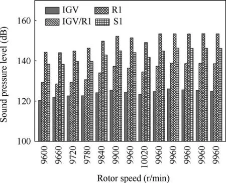
Fig. 13 Sound pressure level at different testing positions.
As shown in Fig. 14, it is found that the characteristic frequency noise signal corresponding to high level rotor blades vibration at the four testing positions is the identical noise source. The phase relation of the characteristic frequency is lagging in turn from IGV to S1. So this characteristic frequency noise source should originate behind the first stage rotor blades at least.

Table 1 Phase difference of the characteristic frequency.
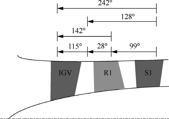
Fig.14 Phase relation diagram of characteristic frequency noise in compressor.
4.4. Characteristic frequency
In the frequency spectrum analysis mentioned in Section 3.2,the resolution ratio maybe too coarser to demonstrate the detailed composition of the frequency spectrum. Therefore,when high level vibration occurs on the first stage of rotor blades, the frequency spectrum measured above the first stage of rotor blades is operated to find out the detailed structural characteristics near 1402 Hz component by improving the frequency resolution (see Fig. 15). And the similarity of the wall pressure signatures of completely different machines is shown in Fig. 16, with a low-pressure compressor which generated high sound pressure levels with a strong tonal component in Fig. 16(a),7,9and a high pressure compressor which had blade vibration problem in Fig. 16(b).10
It is clear that a hump occurs with sum and difference frequencies.Relevant literature also mentioned and explained the specific frequency combination relationship.21,22This is a typical characteristic for slip conditions between the rotor and the rotating unsteady flow structure. In contrast,as the characteristic frequency a sharp peak appears on the noise spectrum,which is also the typical characteristic of acoustic resonance(AR).
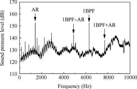
Fig. 15 Noise frequency spectrum measured above R1.
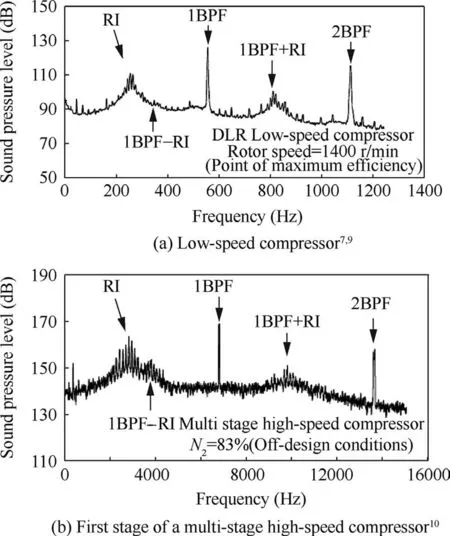
Fig. 16 Pressure spectra at casing wall, upstream from leading edge of rotor.
The frequency spectrum near 1402 Hz component measured above the first stage of rotor blades is accounted by improving the frequency resolution. As shown in Fig. 17 and Table 2, a set of peak frequencies appear near 1402 Hz when high level rotor blades vibration occurs.And these frequencies are centered at 1410 Hz with equal interval about 166 Hz between different peaks which exactly match with rotating speed of rotors.
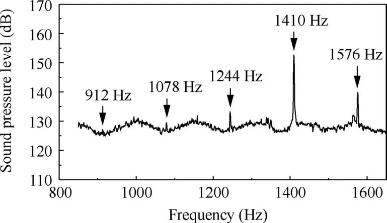
Fig. 17 Zoomed noise frequency spectrum.

Table 2 Characteristic frequency of zoomed spectrum.
That means the characteristic frequency 1410 Hz and its side-band frequencies are generated by modulation of a rotating noise source at the rotor speed.Combining with the results in Section 4.3, the propagation state of the characteristic frequency noise source should be from back to forward with a helix structure which presents the similarity status with the investigation of Hellmich at the University of Hannover when acoustic resonance occurred (see Fig. 18).19
4.5. Blades vibration source analysis
It is mentioned in the relevant literature10that the instability pressure wavep(φF,t)in the compressor presenting the circumferential rotation can be described as a series of sine waves with different circumferential mode numberαunder the fixed coordinate frame (F). And the amplitudeAand the phase angleφchange with the time. Thus the pressure wave form can be expressed as

If the rotating noise source frequency(RS)is/2π,in the noise source coordinate frame (S), Eq. (1) can be the represented as
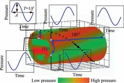
Fig. 18 Helix acoustic mode when acoustic resonance occurred(Hellmich 2006).19
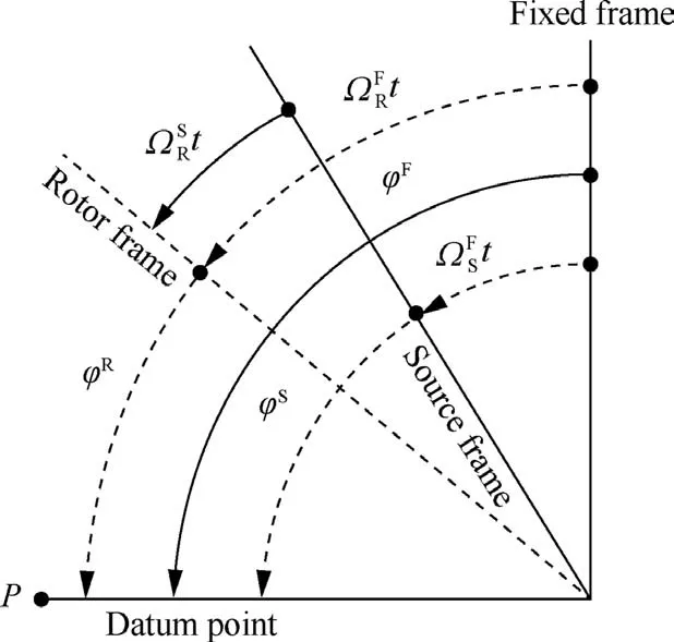
Fig. 19 Relative relation of rotating noise source frequency at different coordinate system.

Similarly, in the rotor blades coordinate frame (R), the above pressure fluctuation can be expressed as

The schematic diagram of the rotating direction of the rotating noise source coordinate frame and the rotor blades coordinate frame relative to the fixed coordinate frame is shown in Fig. 19.
So in the different coordinate frame, the noise frequency conversion relation can be expressed as

Therefore, the pressure wave form can be rewritten as

The rotating noise source frequency/2π can be obtained in the fixed coordinate frame

Considering the rotating noise source propagates forward or backward in the compressor, mode numberαof the source is indicated as

Because there are no other excitation sources related to blades vibration in the compressor.The unsteady pressure fluctuation near to rotor blades may lead to this vibration phenomenon. Because when high level vibration occurs on the first stage of rotor blades the vibration frequency is about 746 Hz, the rotating noise source is evaluated as
S/2π=746 Hz. The rotating speed of this frequency is expressed as=166 Hz in the fixed coordinate frame synchronized with rotor blades. The circumferential fluctuation of the rotating noise source will lead to different circumferential mode number α.The frequency of the rotating noise source measured in the fixed coordinate frame can be calculated inversely though substituting the above/2π andinto Eq.(9).The computed results are presented in Table 3.
Through the above analysis, it is found that the frequency 1410 Hz and its side-band frequencies with equal frequency interval are recovered. Therefore, the mechanism of the high level vibration on the first stage of rotor blades and the characteristic frequency noise source can be expounded. However,it should be noted that the noise frequencies of other circumferential mode numbers have not appeared in the noise signal spectrum.That may be associated with the inner structure size of the compressor, which results in the frequency cutoff at other modes. Furthermore, the circumferential modaldistribution of the rotating noise source should be measured tentatively.And the amplitude and the pressure fluctuation frequency of the noise should be captured on the blade.Thereby,the investigation presented in this paper can be verified doubtlessly.
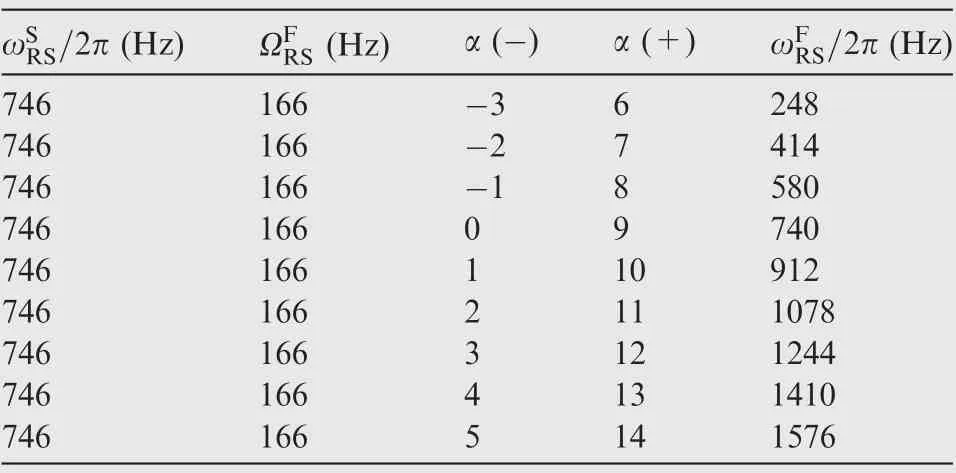
Table 3 Inverse results of rotating noise frequency.
5. Conclusions
(1) In this investigation,an experiment on a multistage high pressure compressor is implemented. An acoustic waveguide system is used for the casing pressure measurement.And this system can provide support for pressure signal testing at higher temperature and pressure through further improvement.
(2) When high level vibration occurs on the first stage of rotor blades,the noise spectrum presents typical characteristic for discrete multi-tone in the compressor. The amplitude of blade vibration displacement and the SPL of characteristic frequency noise increases and decreases simultaneously, which reaches the maximum value at the same time.
(3) The characteristic frequency merely occur on the specific speed range, which has the association with structure adjustment of the compressor. And the characteristic frequency will be locked in a specific range which presents no variation with the rotating speed. The noise source of this frequency should originate behind the first stage rotor blades at least.
(4) When high level vibration occurs on the first stage of rotor blades, the noise spectrum presents a sharp peak and the propagation state is a helix structure in the compressor. It can be confirmed that acoustic resonance occurs in the multistage compressor.
(5) The acoustic resonance frequency and its side-band frequencies are generated by modulation of a rotating noise source with the rotor speed.The acoustic resonance frequency is the excitation source of the vibration of the first stage of rotor blades through the transformation at different coordinate systems.
Acknowledgements
This study was co-supported by the National Natural Science Foundation of China (Nos. 51576009, 11661141020 and 51711530036), and the Aeronautical Science Foundation of China (No. 20151554002).
 CHINESE JOURNAL OF AERONAUTICS2020年3期
- CHINESE JOURNAL OF AERONAUTICS的其它文章
- Experimental investigation on operating behaviors of loop heat pipe with thermoelectric cooler under acceleration conditions
- Investigation of hot jet on active control of oblique detonation waves
- Unsteady wakes-secondary flow interactions in a high-lift low-pressure turbine cascade
- Effect of protrusion amount on gas ingestion of radial rim seal
- Optimization design of chiral hexagonal honeycombs with prescribed elastic properties under large deformation
- A global solution for robust parameter design of aeronautical electrical apparatus based oninteractions analysis and polynomial fitting
