Two-dimensional launch window method to search for launch opportunities of interplanetary missions
Junhong DUAN, Yuefeng LIU
a Air and Missile Defense College, Air Force Engineering University, Xi’an 710051, China
b Science and Technology on Electro-optic Control Laboratory, Luoyang 471000, China
KEYWORDS Interplanetary mission;Launch opportunity;Pock-chop plot;Rendezvous;Time-of-flight
Abstract Accurate and highly efficient approaches to obtain mission opportunities are still the goals of mission planners of interplanetary explorations. The search for launch opportunities not only determines the specified launch window of the mission but also presents the performance requirements for the interplanetary probe and its launch vehicle. An effective method, namely the two-dimensional launch window method, is developed from a completely new perspective to determine all the launch opportunities of the mission in this research. For a fixed launch time,the method to determine all the time windows in the dimension of Time-of-Flight (TOF) is firstly proposed and these time windows represent all the launch opportunities for the given launch time.And then,the two-dimensional launch window method is proposed,which computes the time windows in both the launch time and TOF dimensions to achieve all launch opportunities of the mission. Numerical examples are provided to demonstrate the accuracy and high efficiency of the method. Compared with the widely-used pock-chop plot method, the proposed method reduces the computational time by two orders of magnitude for the same search precision,and thus is especially suitable for the cases involving rapid, high-precision, and/or large-scale searches for mission opportunities.
1. Introduction
Ballistic missions1,2to the planets especially near-Earth asteroids have been receiving more and more interest of the scientific community and of those searching for resources near the Earth.3The mission planning of interplanetary explorations involves many constraints such as expected launch period,acceptable Time-of-Flight (TOF) of the probe, and available launch energy that the launch vehicle offers.These constraints are closely related to the design of the probe and the launch vehicle. How to determine the launch opportunities under all these constraints is a key problem to be solved in the mission planning.
The existing methods to search for mission opportunities can be divided into two categories: the methods to determine all the launch opportunities and the optimization methods to achieve the global or local optimal launch opportunity. The widely-used method to obtain all the launch opportunities is the pock-chop plot method4,5presented by Sergeyevsky et al.For the given launch period and TOF interval (or arrival time interval) of a particular mission, the method computes the heliocentric two-impulse transfer orbit for each combination of launch time and TOF using the Lambert algorithm, and then draws the pock-chop plots/contour maps to obtain all the launch opportunities. The contour maps show intuitively the distribution of all launch opportunities in the whole search space and enable the planners to choose the final mission opportunity flexibly. Additionally, the method can be used not only to estimate the feasibility and cost of the mission to a given planet in terms of trajectory performance but also to support the preliminary design of low-thrust6-9and gravityassist10-13interplanetary missions. However, this method is essentially an ergodic one and it fails to introduce various mission constraints into the searching process to reduce the search space.And thus,the method has a poor efficiency,and its computational time increases rapidly for a higher search precision.Therefore, the method is not very convenient for three typical cases:(A)The search space is very large;(B)A high search precision is required; (C) The search for launch opportunities is required for a large group of selected planets,especially newly discovered asteroids.
To improve the search efficiency, some optimization algorithms such as the global-local optimization algorithms14,15and global optimization algorithms16-20have been developed.As to the global-local optimization algorithms, some hybrid optimization approaches14,15were put forward and these approaches combined the global search properties of genetic algorithms with the local search characteristics of the gradient-based optimization methods. And the genetic algorithm was used to produce a good initial guess for the local gradient-based optimization method. The global optimization algorithms mainly include Differential Evolution (DE),DIvided RECTangles (DIRECT), simple Genetic Algorithm(GA), Multilevel Coordinated Search (MCS), and so on. Bessette and Spencer16compared the performance of various global search algorithms, and the results suggested that determining which particular global search algorithm is most appropriate for trajectory optimization is still a debatable issue. Different algorithms have different performance and are suitable for different cases. Additionally, according to two ESA-funded studies,17,18the quality of the solutions,which are obtained with even a leading global search algorithm such as DE,19,20heavily depends on the proper selection of the routine’s tuning parameters.
One problem of the optimization algorithms is that they can only provide a local or global optimal solution.And it limits the flexibility of mission planning in some extent.For example,there are the cases,in which the launches or arrivals taking place over the holidays such as Spring Festival and Christmas are to be avoided or some unexpected circumstances occur right before the launch of the probe.In such cases,the optimal solution becomes unsuitable or even infeasible. It is not very convenient for the optimization algorithms to deal with such cases. To solve this problem, these algorithms generally need to be combined with the pock-chop plot method to determine a feasible launch opportunity near the optimal solution.
In this research, a rapid and accurate method, namely the two-dimensional launch window method, is developed to determine all launch opportunities of the interplanetary rendezvous/flyby mission. The method computes the time windows in both the launch time dimension and TOF dimension in an iterative way to obtain all the launch opportunities.Compared with the widely-used pock-chop plot method, the proposed method is capable of achieving all launch opportunities of the mission with fairly high efficiency and the computational time is reduced by two orders of magnitude. This improved efficiency brings three main benefits: (A) allowing the mission planners to determine quickly how much the various constraints are needed to be relaxed to allow for a better selection of mission opportunities; (B) reducing greatly the time spent by the cases involving a large search space and/or calling for a high search precision; (C) making it much more convenient to select the mission target from a large group of candidate planets. Therefore, the proposed method is a promising alternative to the pock-chop plot method in some certain cases.
The proposed two-dimensional launch window method is applicable to both the rendezvous and flyby missions. However, for the sake of simplicity, only the rendezvous mission is considered in the presentation. The remainder of the paper is organized as follows. First, the method to determine all the launch opportunities for a fixed launch time is established.On this base, the two-dimensional launch window method is developed. Finally, numerical examples are provided to demonstrate the proposed method.
2. Problem formulation
For the interplanetary rendezvous mission,the problem is formulated in the orbital coordinate frame oxyz,in which the origin is located at the center of the Sun,the x axis points radially outward to the current position of the Earth,the z axis is in the direction of the angular momentum of the Earth’s orbit, and the y axis is in the orbital plane of the Earth, completing the right-hand triad,as shown in Fig.1.At the launch time Tlaunch,the Earth and the planet are assumed to be at the points P1and A0,respectively.In the frame oxyz,let the position and velocity vectors of the Earth at P1be r1=[r1,0,0]Tand v1=[v1x,v1y,0]T, the angular momentum of the Earth’s orbit be hE=[0,0,hE]T, and the launch velocity impulse supplied by the launch vehicle be Δv=[Δvx,Δvy,Δvz]T. After launch,the probe begins remote orbital transfer with an initial velocity of vP, and the angular momentum of the transfer orbit is denoted by hP=[hPx,hPy,hPz]T. The probe rendezvouses with the planet at point A1with a TOF of tf. The velocity vectors of the probe and planet at A1are vPA1and vA1, respectively,and the arrival velocity impulse provided by the probe is Δv′.The angle between the transfer orbital plane of the probe and the orbital plane of the Earth is defined as the relative inclination, denoted by ir, as shown in Fig. 1.
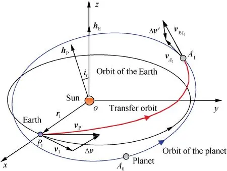
Fig. 1 Geometry of interplanetary rendezvous mission.
For the rendezvous mission, the constraints considered in this research are given as follows:
(1) Time constraints
The launch time and TOF of the probe are expected to be within the time intervals [Tstart, Tend] and [Tfmin, Tfmax],respectively.
(2) Energy constraints
The launch energy per unit mass,C3=||Δv||2, supplied by the launch vehicle does not exceed C3max, and the magnitude of arrival velocity impulse, Δv′, provided by the probe is not more than ΔVPmax.
(3) Communication-range constraint
The maximum communication range between the probe and the Earth is denoted byRmax, and the communication range at encounter does not exceedRmax.
For the flyby mission, all the constraints given above are generally necessary except the constraint on the arrival velocity impulse.
To achieve all the mission opportunities under these constraints, this research endeavors to develop a highly efficient method from the perspective of accessibility of the points on the planet’s orbit. For simplicity, the method to solve all the mission opportunities for a given launch time is firstly to be investigated.
3. Method to determine all the launch opportunities for a fixed launch time
For the target planet of the interplanetary mission, the heliocentric two-body transfer orbit of the probe can be determined through the Lambert algorithm as long as the launch time,Tlaunch, and the TOF, tf, are given. If the obtained ballistic transfer orbit satisfies all the constraints of the mission, the combination of launch time and TOF, (Tlaunch, tf), is called a launch opportunity. For a fixed launch time,Tlaunch∈[Tstart, Tend], all the corresponding launch opportunities are closely related to the accessibility of the points on the planet’s orbit for the probe, which is located at the launch point determined by Tlaunchon the Earth’s orbit.
Therefore, for the given launch time, the set of all the potentially accessible points on the planet’s orbit, namely the Potentially Accessible Zone (PAZ), is firstly analyzed in this section. And then, the PAZ is associated with all the potential TOFs of the probe, and the set of all the meaningful TOFs, namely the TOF set, is determined based on the constraint on the TOF. Finally, the set of all the feasible TOFs, called the launch set, is obtained using the proposed multi-boundary-point searching algorithm. The launch set represents all the launch opportunities for the fixed launch time.
3.1. Determination of PAZ
At the launch time Tlaunch, the unit vectors of the frame oxyz are denoted by i, j, and k. The angular momentum of the probe’s transfer orbit can be expressed as

The relative inclination ircan be given by


The boundary transfer orbital planes determined by ir=irmaxand -irmaxare called the positive boundary plane and negative boundary plane, respectively. For each boundary plane, as the tangent point is unique, there is only one transfer orbit on the plane. And h+Pand h-Pare the angular momentums of the two transfer orbits on the positive and negative boundary planes, respectively. In all, the feasible domain of iris [-irmax, irmax], and the negative and positive boundary planes form the envelope of all feasible transfer orbital planes.
Generally, any feasible transfer orbital plane intersects the planet’s orbit at two points. The crosspoints of the planet’s orbit and all the feasible transfer orbital planes constitute two arcs on the planet’s orbit, as shown in Fig. 3. The union of these two arcs is essentially the collection of all the potentially accessible points on the planet’s orbit for the probe at P1, and thus is called the PAZ. The two arcs, namely the PAZ 1 and 2, are both the subsets of the PAZ. The PAZ 1 and 2 are represented by [θ1min,θ1max] and [θ2min,θ2max], respectively,in which θ1min,θ2min,θ1max,and θ2maxare the true anomalies of the crosspoints of the planet’s orbit and the two boundary planes. The method to determine the PAZ is given below.
In the orbital coordinate frame oxyz,it is assumed that the angular momentum and eccentricity vectors of the planet’s orbit are hCPand eCP, respectively. The two crosspoints of the positive boundary plane and the planet’s orbit are firstly to be determined, which can be represented by their true anomalies,and, where<.


Fig. 4 Determination of PAZ 1 and 2.

It can be seen from Eq.(11)that θ1min>θ1max.However,for the sake of consistency, the PAZ 1 is still expressed as[θ1min,θ1max], which is defined as

3.2. TOF set for PAZ
For the given launch time Tlaunch,the PAZ presents all the possibly reachable points on the planet’s orbit for the probe.Thus the rendezvous point for any launch opportunity at Tlaunchdefinitely lies within the PAZ.However,for a launch opportunity,the TOF of the probe must equal the time spent by the planet flying along its orbit from the initial position A0at launch time Tlaunchto the rendezvous point in the PAZ. Therefore, once a point, denoted by A1, in the PAZ is viewed as a rendezvous point, all the corresponding potential TOFs for the probe can be determined by computing the times for the planet moving from its initial position A0to the point A1along its orbit.Note that the multi-revolution case for the planet has been taken into account. Furthermore, the PAZ can be associated with the set of all potential TOFs of the probe, which are corresponding to all the points in the PAZ. This set is called the Potential Time-of-Flight Set (PTOFS) in this research. The determination of this set is introduced below.
For simplicity, we first investigate the case in which the probe’s TOF is less than the orbital period of planet. In this case, there is a one-to-one match between any point A1in the PAZ and the time spent by the planet moving from initial position A0to the point A1,and the movement time of the planet is essentially the unique potential TOF for the probe.Thus,the point A1can be represented by the potential TOF of the probe. Let the true anomalies of the points A0and A1be θA0and θA1, and then the eccentric anomalies of these two points,denoted by EA0and EA1, can be derived from the following equation:

where rAiis the heliocentric distance of point Ai, and aCPand eCPare the semi-major axis and eccentricity of the planet’s orbit, respectively.
The time spent by the planet moving from the point A0to A1within one orbital period is denoted by T(θA0,θA1), which can be given, according to the Kepler’s equation, by

At the launch time, there exist three cases for the positional relationship of the planet and PAZ on the planet’s orbit, as shown in Fig. 5. The whole PAZ can be represented by the collection of potential TOFs corresponding to all the points in the PAZ. Taking the case in which the planet lies in the PAZ 1 (see Fig. 5(a)) for example, the PAZ 1 can be represented by the union of two time intervals,[0,T(θA0,θ1max)] and [T(θA0,θ1min),TCP], where TCPis the orbital period of the planet. The PAZ 2 can be represented by the time interval, [T(θA0,θ2min),T(θA0,θ2max)]. Thus the whole PAZ can be expressed as the union of all these three time intervals.
In the discussion above, the probe’s TOF is assumed to be less than the orbital period of the planet. And in this case,there is a one-to-one match between any point in the PAZ and the potential TOF of the probe. However, for a general case, there would be theoretically countless movement times of the planet for any given point in the PAZ because the planet could reach the given point periodically. Therefore, for any point A1in the PAZ, all the potential TOFs of the probe can be given by tf=tf0+k·TCP, k=0,1,2,···, where tf0is the corresponding potential TOF of the probe within one orbital period of planet.Furthermore,for the whole PAZ,the PTOFS can be expressed as the union of countless time intervals. For example, the PTOFS in the case shown in Fig. 5 (a) can be expressed as

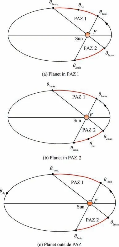
Fig. 5 Positional relationship of the planet and PAZ.

Given the mission constraint on the probe’s TOF, that is,tf∈[Tfmin, Tfmax], the set of all the meaningful TOFs for the PAZ can be determined by which is called the TOF set in this research. The TOF set is generally the union of several time intervals, each of which is called a subset of the TOF set. For the given launch time Tlaunch, all the feasible TOFs for the probe are included in the TOF set, and each feasible TOF determines a launch opportunity. Our purpose is to find all the launch opportunities in the TOF set.
3.3. Method to determine the launch set in TOF set
To determine all the launch opportunities, that is, all the feasible TOFs, in the TOF set, the definitions of three basic and important concepts, the encounter set, rendezvous set, and launch set, are firstly to be introduced, and then the method to determine all the launch opportunities in the TOF set is presented.
Definition 1. Assume that the probe is launched at the given time, Tlaunch∈[Tstart, Tend], and encounters with the planet after a TOF of tf.If the required launch energy does not exceed C3max,the time tfis called an encounter TOF.The set of all the encounter TOFs in the TOF set is called the encounter set,denoted by TF1.
Obviously, any encounter TOF in the encounter set TF1determines a unique encounter point on the planet’s orbit as well as a heliocentric transfer orbit.The set of all the encounter points determined by encounter set TF1is called the encounter zone.Since any point in the encounter zone is accessible for the probe at the fixed launch point,the encounter zone is definitely within the PAZ. In addition, considering the possible multi-revolution case for the planet,any point in the encounter zone may be corresponding to several encounter TOFs in the encounter set.
Definition 2. Assume that the probe is launched at the given time, Tlaunch∈[Tstart, Tend], and encounters with the planet after a TOF of tf.If the required launch energy does not exceed C3maxand the magnitude of arrival velocity impulse does not exceed the maximum magnitude ΔVPmax,the time tfis called a rendezvous TOF. The set of all the rendezvous TOFs in the TOF set is called the rendezvous set, denoted by TF2.
In the rendezvous set TF2,any rendezvous TOF determines a unique rendezvous point on the planet’s orbit. The set of all the rendezvous points determined by rendezvous set TF2is called the rendezvous zone. It can be deduced that the rendezvous zone is within the encounter zone.
Definition 3. Assume that the probe is launched at the given time, Tlaunch∈[Tstart, Tend], and encounters with the planet after a TOF of tf. If the required launch energy and arrival velocity impulse do not exceed C3maxand ΔVPmaxin magnitude,respectively,and meanwhile the communication range at encounter is not more than the maximum range Rmax,the time tfis called a launch TOF.The set of all the launch TOFs in the TOF set is called the launch set, denoted by TF3.
Similarly,the set of all the rendezvous points determined by the launch set is called the launch zone,and the launch zone is within the rendezvous zone.
According to the definitions of encounter set TF1, rendezvous set TF2, and launch set TF3, we have TF1⊇TF2⊇TF3. The relationship of these three sets is shown in Fig. 6.
The launch set TF3essentially presents all the launch opportunities for the fixed launch time Tlaunch. And it can be seen from Fig. 6 that the constraints on the launch energy,the arrival velocity impulse, and the communication range at encounter can be introduced into the search process step by step, reducing the search space gradually, until the set of all launch opportunities in the TOF set, that is, the launch set TF3, is finally obtained.
As shown in Fig. 6, the search process can be divided into three steps, and each step deals with the constraint of current step and aims to determine the set of all the TOFs satisfying this constraint. Each of the three steps can be conducted through an original algorithm, namely the multi-boundarypoint searching algorithm, which can determine all the subintervals satisfying a given constraint in an interval. Next, we will show how to derive the encounter set TF1from the TOF set TF (that is, Step 1 in Fig. 6) using the multi-boundarypoint searching algorithm.


Fig. 8 Typical distribution of positional zones.
4. Two-dimensional launch window method
As mentioned above,the probe’s launch time is required to be within the time interval[Tstart, Tend].If we searched for launch opportunities in [Tstart, Tend] in an ergodic way using the method to determine the launch set for a fixed launch time,the search process would still be somewhat computationintensive. In the dimension of launch time, since the launch opportunities distribute only in some separate subintervals in[Tstart, Tend], all the launch opportunities of the interplanetary mission can be determined through the following steps:
(1) Determine all the subintervals, [Tsi, Tei],i=1,2,···,which contain launch opportunities, in [Tstart, Tend]using the multi-boundary-point searching algorithm, in which the required constraint is that the considered launch time should contain launch opportunities.Therefore, in the search process, we need to compute the launch set for current launch time using the method presented in Section 2 and then to check whether the launch set is null. The obtained subintervals,[Tsi, Tei],i=1,2,···, are in fact the time windows in the launch time dimension, as shown in Fig. 9, where there exist two time windows, [Ts1, Te1] and [Ts2, Te2],in the launch time dimension.

Fig. 9 Illustration of two-dimensional launch window method.
(2) Search in the subintervals, [Tsi, Tei], i=1, 2, ···, one by one in an ergodic way to achieve all the launch opportunities of the mission. In the ergodic process,the launch set, that is, the time windows in the TOF dimension, is determined for any launch time in[Tsi, Tei], i=1, 2, ···. Note that the number of time windows in the TOF dimension is variable for a launch time. For example, as shown in Fig. 9, the launch time T1has merely one time window, [tf1,1, tf1,2], in the TOF dimension while the launch time T2has three time windows, [tf2,1, tf2,2], [tf2,3, tf2,4], and [tf2,5, tf2,6].
The above method achieves all the launch opportunities of the interplanetary mission by computing the time windows in both launch time and TOF dimensions, and all the time windows of these two dimensions determine several twodimensional launch windows in the Tlaunch-tfplane (see Fig.9),which represent all the launch opportunities of the mission. Therefore, the method is called the two-dimensional launch window method. Compared with the widely-used pock-chop plot method, this method is capable of achieving all launch opportunities of the mission accurately and efficiently.The computing process of the two-dimensional launch window method is shown in Fig. 10.
It should be pointed out that the search step τ in the multiboundary-point searching algorithm could be set as a fixed and somewhat big step, denoted by τlaunch, when we determine the time windows, [Tsi, Tei],i=1,2,···, in the launch time dimension. Although this may induce the missing of time windows shorter than τlaunch, the error is well acceptable. This is because the launch window is generally expected to be a long one in engineering so that we can determine the specific launch time of the probe flexibly in case of unexpected circumstances.Too short time windows are not very meaningful in engineering.
For the flyby mission, only the constraints on the launch energy and the communication range at encounter are required,and the arrival velocity impulse is not needed.Therefore, we just need to let TF2=TF1for any launch time when searching for launch opportunities of the flyby mission using the two-dimensional launch window method.
5. Numerical examples
Two examples are provided to demonstrate the accuracy and effectiveness of the proposed two-dimensional launch window method. In each example, two methods, the commonly used pock-chop plot method and the two-dimensional launch window method,are adopted to calculate all launch opportunities of the mission, and the merits of the proposed method are demonstrated by comparison of the results obtained by these two methods. The computation platform is a computer with an Intel® CoreTM i7-3770 CPU processor and 4.00 GB memory.
(1) Example 1: Rendezvous mission to the 4660 Nereus
Take the near-Earth asteroid, 4660 Nereus, as the chosen planet of the interplanetary rendezvous mission, which was once the target planet of the Japanese MUSES-C probe. The orbital elements of the asteroid and the Earth are given in Table 1.As to 4660 Nereus,suppose that no priori knowledge about possible rendezvous opportunities is known, and thus we search for opportunities in a long launch period from 12:00:00 UT January 1, 2019 to 12:00:00 UT December 31,2022, that is, [Tstart, Tend]=[2458485, 2459945] (Julian Date).The acceptable TOF interval,[Tfmin, Tfmax],is[150,750](days).Additionally, assumeC3max=36 km2/s2, ΔVPmax=2.0 km/s,and Rmax=4×10⁸km. The search precisions in the launch time and TOF dimensions are both required to be 1 day.

Fig. 10 Flowchart of two-dimensional launch window method.
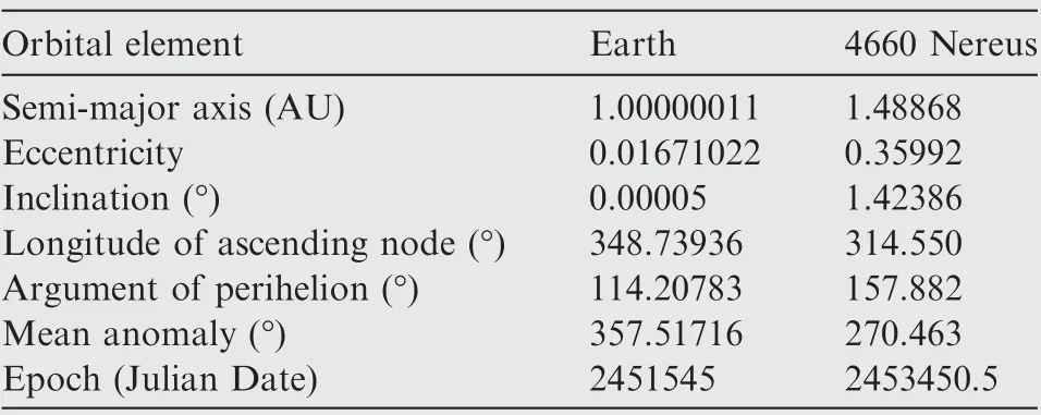
Table 1 Orbital elements of the Earth and 4660 Nereus.
For the pock-chop plot method, the search steps of the launch time and TOF are both set as 1 day, and the twoimpulse transfer orbit for each combination of launch time and TOF is computed using the Lambert algorithm. Based on the computation results, the contour maps are drawn for C3, arrival velocity impulse, and communication range at encounter, as shown in Figs. 11 (a), (b), and (c). The units of the numerical markings in Figs. 11 (a), (b), and (c) are km2/s2, km/s, and 108km, respectively.
It can be seen from Fig.11(a)that C3is less than C3maxfor any point within the contour lines labeled with 36, which means that all these points are feasible for the launch vehicle.In Fig.11(b), the magnitude of arrival velocity impulse is less than ΔVPmaxfor any point within the contour lines labeled with 2, and thus all these points are feasible for the probe. The launch-energy contour lines labeled with 36, the arrivalvelocity-impulse contour lines labeled with 2, and the communication-range contour lines labeled with 4 are plotted in a common figure, Fig. 11 (d), where there exist five communication-range contour lines labeled with 4, denoted by Li(i=1, 2,···, 5). The union of the areas enclosed by the launch-energy contour lines labeled with 36 is denoted by Area1, and the union of the areas enclosed by the arrivalvelocity-impulse contour lines labeled with 2 is denoted by Area2.Given the trends of communication-range contour lines in Fig. 11 (c), all the points, which are within the intersection of Area1and Area2and meanwhile lie between the lines L2and L3,or L4and L5,are essentially all the launch opportunities of the mission. All these launch opportunities constitute five green areas, A-, B-, C-, D-, and E-, in Fig. 11 (d). The areas, A-,B-,and C-,are large areas,while D-and E-are very small,whose enlarged views are provided as well.The computational time of the pock-chop plot method,not including the time for drawing and analyzing the contour maps, is 100.18 s.
In the proposed two-dimensional launch window method,let τlaunch=10 days, τS=5 days, and N=16 (in Eq. (18)).The search precision is set as 1 day when we search for the boundary points of time windows in both launch time and TOF dimensions, and the search step is also set as 1 day when we search in the time windows of launch time dimension by using the method to determine the launch set for a fixed launch time. The result achieved by this method is given in Fig. 12,where there also exist five areas, A, B, C, D, and E, corresponding to the areas, A-,B-,C-,D-, and E-, in Fig. 11 (d). The enlarged views of the five areas, A, B, C, D, and E, are shown in Fig.13.It can be seen from Fig.13 that these five areas are all exactly bounded by the contour lines determined by the mission constraints. This demonstrates the accuracy of the two-dimensional launch window method. The computational time of this method is merely 3.819 s,that is,3.8%of the time cost by the pock-chop plot method.
(2) Example 2: Flyby mission to the 1943 Anteros
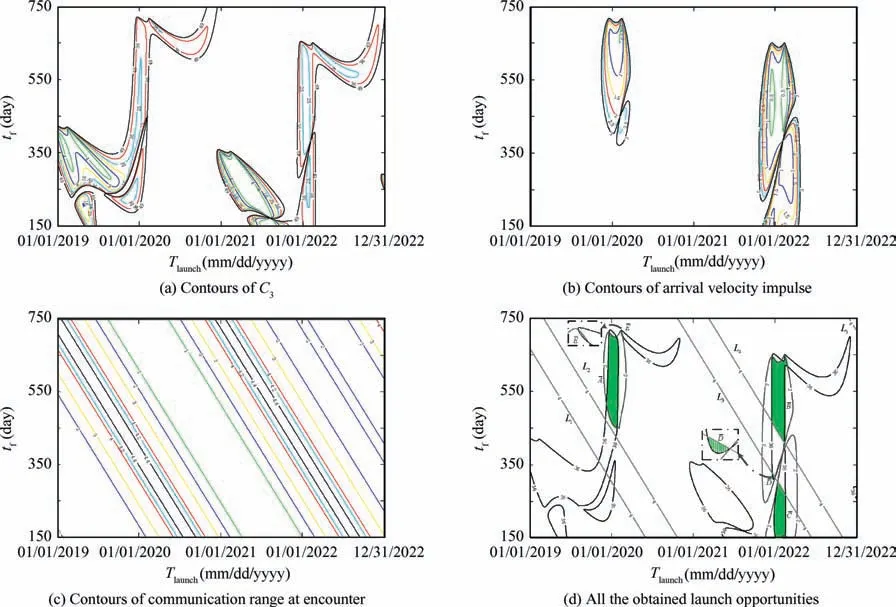
Fig. 11 Results obtained by pock-chop plot method.
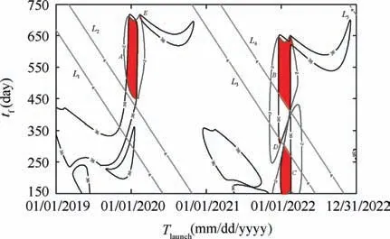
Fig. 12 Result obtained by two-dimensional launch window method.
The orbital elements of the near-Earth asteroid,1943 Anteros, are given in Table 2. In this example, the search for mission opportunities is performed in a small search space, in which the launch time ranges from 12:00:00 UT June 19,2020 to 12:00:00 UT August 28, 2020, and the TOF ranges from 220 days to 290 days. And the search precisions in the launch time and TOF dimensions are both required to be 1 h. Let C3max=16 km2/s2and Rmax=1.08×10⁸km, and note that no arrival velocity impulse is needed for the probe at encounter.
Orbital element Value

Table 2 Orbital elements of the 1943 Anteros.
In the pock-chop plot method, the search steps in the launch time and TOF dimensions are both set as 1 h.The contour maps of C3and communication range at encounter are shown in Figs. 14 (a) and (b). And the units of the numerical markings in Figs.14(a)and(b)are km2/s2and 108km,respectively. According to these two contour maps, all the launch opportunities of the mission can be obtained, as shown in Fig. 14 (c). The computational time of the pock-chop plot method is 307.52 s.

Fig. 13 Enlarged views of five areas.

Fig. 14 Results obtained by pock-chop plot method.
In the proposed two-dimensional launch window method,the values of the parameters, τlaunch, τS, and N, are the same as that in Example 1. The search precision is set as 1 h for the boundary points of the time windows in both of the two dimensions. And the search step is also set as 1 h when we search in the time windows of launch time dimension. The result achieved by this method is given in Fig. 15, where all the obtained launch opportunities (i.e. red area) are exactly bounded by the contour lines determined by the mission constraints. The computational time of this method is merely 4.11 s, that is, 1.3% of the time cost by the pock-chop plot method.

Fig. 15 Result obtained by two-dimensional launch window method.
6. Conclusions
An effective method,namely the two-dimensional launch window method, was developed in this research, which computes the time windows in both the launch time and TOF dimensions to obtain all the launch opportunities of the interplanetary rendezvous/flyby mission. The method introduces mission constraints into the searching process step by step to reduce the search space and thus improves greatly the search efficiency.Compared with the pock-chop plot method, the proposed method reduces the computational time by two orders of magnitude, and thus is especially suitable for the cases involving rapid, high-precision, and/or large-scale searches for mission opportunities. In addition, just like the pock-chop plot method,the proposed method can also be combined with optimization algorithms to achieve the optimum launch opportunity of the mission. In all, it is a promising alternative to the pock-chop plot method in some certain cases.
Acknowledgment
This work was co-supported by the National Natural Science Foundation of China (No. 11502300), the Science and Technology on Electro-optic Control Laboratory and the Aerospace Science Foundation of China (No. 20165196018).
 CHINESE JOURNAL OF AERONAUTICS2020年3期
- CHINESE JOURNAL OF AERONAUTICS的其它文章
- Experimental investigation on operating behaviors of loop heat pipe with thermoelectric cooler under acceleration conditions
- Investigation of hot jet on active control of oblique detonation waves
- Experimental study of rotor blades vibration and noise in multistage high pressure compressor and their relevance
- Unsteady wakes-secondary flow interactions in a high-lift low-pressure turbine cascade
- Effect of protrusion amount on gas ingestion of radial rim seal
- Optimization design of chiral hexagonal honeycombs with prescribed elastic properties under large deformation
