Impact time control using biased proportional navigation for missiles with varying velocity
Guoxin SUN, Qiuqiu WEN,*, Zhiqing XU, Qunli XIA
a School of Aerospace, Beijing Institute of Technology, Beijing 100081, China
b Harbin Jiancheng Industry Company Limited, Harbin 150030, China
KEYWORDS Guidance;Homing missiles;Impact time;Proportional navigation guidance;Time-varying velocity
Abstract A feasible guidance scheme with impact time constraint is proposed for attacking a stationary target by missiles with time-varying velocity.The main idea is to replace the constant velocity with the future mean velocity; therefore, the existing time-to-go estimation algorithm of the proportional navigation guidance law can be improved to adapt to varying conditions. In order to obtain the prediction of the velocity profile, the velocity differential equation to the downrange is derived,which can be numerically integrated between the current downrange and the target position by the on-board computer.Then,a third-order polynomial is introduced to fit the velocity profile in order to calculate the future mean velocity.At the beginning of each guidance loop,the future mean velocity is predicted and the time-to-go information is updated,based on which a novel biased proportional navigation guidance law is established to achieve the impact time constraint. Finally,numerical simulation results verified the effectiveness of the time-to-go estimation algorithm and the proposed law.
1. Introduction
Recent developments in the field of terminal guidance law have led to increasing interest in the Impact Time Control Guidance(ITCG) problem, which is employed to achieve a cooperative attack to improve the attack effect and enhance the survivability of missiles against the threat of defense systems.1,2To date,numerous advanced guidance laws have been derived via different theories.3-14However, the missile velocity in most of the surveys is assumed to be constant, so most missiles and projectiles possess reduced degrees of control freedom due to the fact that velocity is uncontrollable,which is one of the limits to the practicability of these laws. The flight velocity of most missiles is uncontrolled and can be affected by various factors,including the external forces,the atmospheric environment, and even the flight trajectory shape. Therefore, the assumption of a constant velocity can severely reduce guidance performance and even make the guidance law fail to achieve the terminal constraints.
To the best of the authors’knowledge,it seems that it is virtually impossible to obtain the explicit expression of velocity from the complex equation by a strict mathematical method because the velocity change will be mainly governed by the yet-undetermined acceleration command and the shape of the trajectory,15,16which is one of the main obstacles for designing the ITCG law under varying velocity conditions.Therefore,few studies have attempted to address this problem.
The existing literature can be classified into two types.One is to use numerical-flight or online iteration.In Ref.17,a quadsegment polynomial trajectory-based guidance law was proposed. In this study, online preflight analysis is conducted to generate the estimated reference data. Then, these data are compared with real-time data to correct the time error. Similarly, Ref.18presented a feasible framework for impact time control under varying velocity, which is generalized by a multi-order polynomial of the look angle and the future mean velocity obtained by an online optimization algorithm. Furthermore, a numerical method was also used in the terminal guidance approach proposed in Ref.19for a hypersonic vehicle.By introducing the concept of the predicted range, the guidance law uses the numerical time-to-go prediction law to predict an exact time-to-go. However, using iterative or recursive algorithms, such as in these studies, is computationally inefficient and deeply dependent on the performance of onboard computers. The other is to simplify the dynamics model. Ref.20proposed an integral sliding mode controlbased law that relaxes the constant velocity assumption and only needs the variation range of the missile velocity.However,this law did not take into account the influence of gravity,nor did it consider the induced drag.
Considering the guided impact on a stationary target in a vertical plane, this paper is prepared according to the framework proposed by Jeon et al. in Ref.1, which uses a combination of the well-known Proportional Navigation Guidance(PNG)law and the feedback of the impact time error between the impact time by PNG and the prescribed impact time.Note that the time-to-go expression used in this study is obtained by dividing the length of the trajectory by the constant velocity,and the trajectory shape is independent of the velocity, which will be shown in this work. The varying velocity problem can be addressed by replacing the constant velocity with the future mean velocity.First,a prediction algorithm of the velocity profile is derived based on the known trajectory shape of PNG under the assumption of small angles. Then, to calculate the future mean velocity, a third-order polynomial is introduced to fit the appropriate velocity expression, which can be easily integrated. Therefore, the time-to-go estimation with timevarying velocity can be obtained by replacing the constant velocity with the future mean velocity. Finally, note that the easily reformed characteristic is another major advantage of the PNG law; it can be established as a corresponding form to any given terminal constraint, such as the terminal acceleration and the field-of-view.As an example,this study proposes a law using the form of biased PNG.
The remaining part of the paper proceeds as follows.Section 2 illustrates the engagement geometry and dynamics model of the problem.Section 3 derives a prediction algorithm of the velocity profile for PNG. Then, a time-to-go estimation algorithm with varying velocity is provided in Section 4. In Section 5, the proposed algorithm is applied to the biased PNG law. In Section 6, the simulation results are illustrated,and the performance of the proposed law is discussed.Finally,Section 7 presents the conclusion of this study.
2. Problem formulation
The engagement geometry of a homing missile against a stationary target on the ground is formulated in Fig. 1. In this scenario,the missile is supposed to be unpowered in the terminal guidance phase and is modeled as a point mass.To simplify the dynamics, the time-varying velocity V of the missile is assumed within a low Mach number range (Mach <2.0).The other variables of the missile are the normal acceleration command a,the flight path angle γ and the position in the vertical plane (x, y). R refers to the relative distance between the missile and target. λ and ε represent the Line-of-Sight (LOS)angle and the lead angle, respectively. The forces acting on the missile are the lift L,the drag D and the gravity mg,where m is the missile mass and g denotes gravity acceleration.
The dynamics of the aerodynamically controlled missile can be expressed as
where the dot denotes the differentiation with respect to time.The boundary conditions are shown as

The dynamics of Eq. (1) is nonlinear with respect to the accelerate control command a which is defined as

The lift and drag are given as

where ρ is the atmospheric density, which is a function of the altitude y,Srefis the reference area,and CLand CDare the lift and drag coefficients, respectively, which are both dependent on the angle of attack α and the Mach number.16,17Since only a low Mach number is considered,the influence of Mach number is negligible so that the coefficients can be modeled as functions of α, which are well known as15where the lift aerodynamic derivative CαL, the zero-lift drag coefficient C0D,and the induced-drag derivative CαDare all constant factors, which can be obtained by wind tunnel tests or computational fluid dynamics.


Fig. 1 Homing engagement geometry.
Suppose that the missile is guided by PNG, and then the acceleration command can be given as

where N denotes the guidance gain,λ represents the LOS angle rate and gcosγ is the gravity compensation.
Assume that the LOS angle is small, and it can be approximated as

Therefore, the LOS angle rate can be obtained as

3. Prediction of velocity profile
This section aims to determine how the flight velocity changes throughout the flight, which can be used to obtain the future mean velocity.
According to Eq. (1), the downrange x is monotonically increasing with time,so the dynamics can be transformed from time domain to x domain. Under the assumption of a small flight path angle, Eq. (1) can be rewritten as

where the superscript represents the derivative of the parameter to the downrange x.
Similarly, Eq. (8) becomes

Combining Eq. (1), Eq. (3), Eq. (6), Eq. (8), and Eq. (9)yields

Substituting Eq. (9) into Eq. (11), we have

Eq. (12) can be solved as follows:

where b1and b2are boundary conditions and can be expressed as

It can be seen from Eq. (13) and Eq. (14) that the missile trajectory guided by PNG is independent of the velocity; that is to say, the range-to-go is unchanged regardless of whether the velocity is constant.
Substituting Eq. (13) into Eq. (9) yields

Consequently, substituting Eq. (13) and Eq. (15) into Eq.(9), we have

Then, by substituting Eq. (16) into Eq. (6), the accelerate command in x domain can be given as

Furthermore, by combining Eq. (3)~Eq. (5)and Eq. (17),α can be rewritten as

Note that the density ρ is a function of the altitude y, and by using Eq. (13), it can be fitted with an exponential function21as

where ρ0and β0are constant coefficients and can be obtained from the standard atmosphere model.
Substituting Eq. (18) and Eq. (5) into Eq. (4) yields

Then, by substituting Eq. (20) into Eq. (9), the differential equation of velocity with respect to x can be expressed as

Considering there is no analytical solution of Eq. (21), the future velocity profile can be obtained by numerical method such as Euler integral approach and Runge Kutta method.The algorithm for the proposed velocity estimation strategy scheme is presented in Fig.2 in pseudocode form.In addition,if the missile thrust is known during the whole flight phase,there is also a similar way to conduct a prediction for the velocity, which is shown in Appendix A.
4. Estimation of time-to-go under time-varying velocity conditions
After obtaining the future velocity profile,the next question is to calculate the mean value.In order to integrate the velocity,a third-order polynomial function with respect to the downrange x is introduced to fit the velocity curve,which can be expressed as

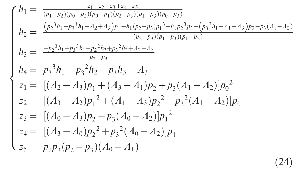
where the coefficients h1,h2,h3,h4can be solved by using four sampling points (pi,Λi),i=0,1,2,3 from the velocity curve.As an example, the points in this paper are selected as
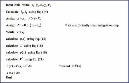
Fig. 2 Pseudocode form for velocity estimation.

Then, applying the four points into Eq. (22) can give the coefficient values as
After obtaining the velocity polynomial, the future mean velocity can be calculated as

According to Jeon et al.,3the length of the PNG homing trajectory can be expressed as

Since the length is independent of velocity, the time-to-go estimation under varying velocity conditions can be obtained by replacing the constant velocity with the future mean velocity, which can be written as

5. Impact time control
The desired impact time and the designed time-to-go are represented by tf, and t
go, respectively, which can be written as

The difference between the designed time-to-go and the estimation of time-to-go is defined as

Then, by using the nonlinear feedback control theory, the law is formed as

where sgn(ξ)is a sign function of ξ,and δ is a function of R.By defining r=1-R/R0, δ can be expressed as

where k2represents the decreasing speed ratio.This given function is used to make δ decrease from 1 to 0 with different decreasing speeds when the range-to-go tends to zero, as shown in Fig. 3.
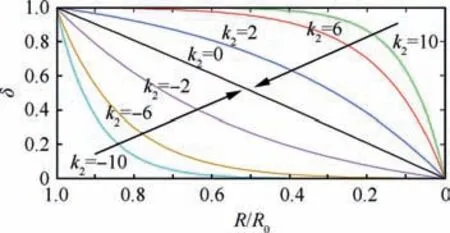
Fig. 3 Pseudocode form for velocity estimation.
The function δ introduced here can avoid undesirable situations that require infinite or unnecessary control commands by the time error when R tends to zero.Furthermore,the control energy can be reasonably distributed by adjusting the decreasing speed of δ.
In addition, k1is a positive constant. If a0is a reasonable value of the initial acceleration, then k1can be given as

where ξ0can be obtained by the time-to-go estimation at the initial time.
6. Simulation results
This section validates the performance of the proposed law in three subsections. The first subsection verifies the accuracy of the proposed time-to-go estimation algorithm. The second subsection investigates the basic characteristics of the proposed law under various initial conditions.In the third subsection, the performance of the proposed guidance laws is compared with other guidance laws. The basic simulation parameters for each situation are listed in Table 1.
6.1. Time-to-go estimation simulation
In this subsection,two sub-simulations are considered to verify the performance of the time-to-go estimation algorithm. The first set of simulations represents ground-to-ground engagements with four scenarios, which are designed to examine the impact of different initial path angles.In these four scenarios,all the initial missile positions are set to(0 km,0 km),and the initial path angles are set to 10°, 20°, 30°, and 40°,respectively.
Fig. 4 illustrates the real and estimated values of several main parameters of the missile, among which the trajectory and flight path angle estimations are obtained using Eq. (13)and Eq. (15), respectively. As shown in Figs. 4(a)-4(c), when the initial path angle is less than 20°, our method can give accurate estimations for the trajectory, the flight path angle and the velocity for the entire flight phase,and there is almost no difference between the real and estimated values. In regard to 30°, the path angle begins to show differences, and there isan increasing error with the initial path angle becoming larger.Fig.4(d)reveals a decreasing error of the future mean velocity as the downrange increases; in all of the scenarios, the maximum error appears at the initial time with increasing values of 2.9%, 3.0%, 3.47% and 3.61%. From the length-to-go curve showed in Fig.4(e),Eq.(26)shows a high-precision prediction of the trajectory length,that is to say,the main estimation error should be from the future mean velocity estimation.As analyzed above, the accuracy of the time-to-go estimation depends on the future mean velocity accuracy, and thus the time-to-go estimation curve illustrates similar performance to the future mean velocity shown in Fig. 4(f) The error maximum is at the initial time with a value of 0.82 s, 0.85 s, 0.88 s and 1.07 s, which is approximately 1% in all of the scenarios and has a decreasing trend in the terminal phase.Overall,these results suggest that the proposed method shows excellent performance in estimating the time-to-go information, especially under small path angles.
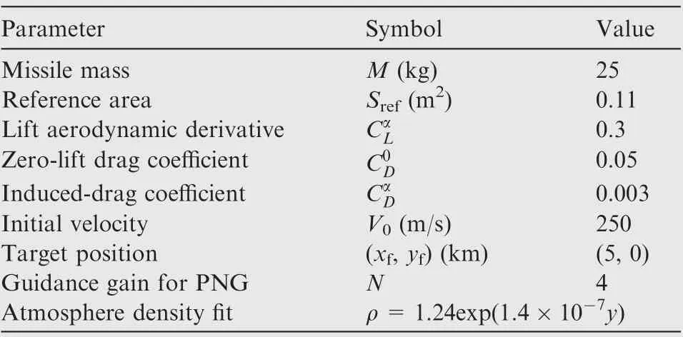
Table 1 Basic parameters for simulation.
The second set of simulations is used to analyze the relationship between different initial launch velocities.In four scenarios, all of the initial path angles are set to 30°, and the initial velocities are set to 200 m/s, 300 m/s, 400 m/s, and 500 m/s. Fig. 5 provides some of the main characteristics of the time-to-go estimation algorithm simulation results under different initial velocities. It can be seen from Fig. 5(a) that all the different initial velocities have the same trajectory shape, which certificates the correctness of the deduction above.Fig.5(b)presents an accurate velocity estimation when the velocity varies from 200 m/s to 500 m/s and shows that an increasing error with the velocity becomes larger.Fig.5(c)and Fig.5(d)illustrate the same trend with varying velocity,which shows good performance in all scenarios.
6.2. Basic characteristics of proposed laws
In this subsection, three scenarios are considered in various initial conditions, and the initial position and the path angle of the missile are considered (0 m, 0 m, 10°), (0 m, 500 m,0°) and (0 m, 1000 m, 0°), respectively. Considering that the desire time should be selected to render ξ0>0, the desire impact time is set to 35 s, and the initial acceleration is set to 3.5 g. Table 2 shows an overview of the effectiveness of the proposed law, and other detailed results are presented in Fig. 6.
Fig. 6(a) depicts that the trajectories become curved in different scenarios. In Fig. 6(b), the flight path angle increases in the front phase and then decreases down in the terminal phase. Fig. 6(c) shows the real and estimated time-to-go information in three scenarios. It can be seen from Fig. 6(c) that the law can make an accurate prediction of time-to-go information, and as seen from Fig. 6(c) and Table 2, the proposed law can achieve impact time control with a terminal error of approximately 0.1 s. Moreover,the difference in the time-to-go is clearly illustrated in Fig. 6(d), which indicates that the differences all converge to zero at the end of the engagement. Fig. 6(e) presents the velocities, the acceleration commands are shown in Fig. 6(f), and the acceleration has a maximum command value at the initial time and decreases to approximately 1 g.

Fig. 4 Time-to-go estimation algorithm simulation results under different initial path angles.
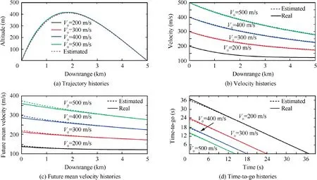
Fig. 5 Time-to-go estimation algorithm simulation results with different initial velocities.

Table 2 Overview of effectiveness of proposed laws.
6.3. Comparison with other guidance laws
The performance of the proposed law is compared with two other laws in this simulation. One is optimal results using the general pseudo spectral optimization software, which is MATLAB-based software.22The other is the law proposed in Ref.18.The simulations are performed under the initial condition of(0 m,0 m,10°),and the desire time is set to 40 s.The parameter set value and the control energy cost function,which is defined as the integral of the square of the acceleration command,are summarized in Table 3.The comparison results are presented in Fig. 7.
Table 3 and Fig.7 illustrate that all these laws can drive the missile to hit the target within the desired time.From Fig.7(a)and Fig. 7(b), the three laws have basically similar trajectories and path angle profiles, and the optimal law has the lowest homing trajectory and path angle in most time. As shown in Fig.7(c),the velocities have a similar distribution.The acceleration command histories are shown in Fig.7(d).The proposed law and the law in Ref.18have similar acceleration profiles,both of which initially generate a larger guidance command than the optimal law.The two laws require a maximum acceleration of approximately 2.7 g, while the optimal result needs only approximately 1.5 g. As shown in Table 3, the optimal law has the lowest energy cost, as expected. The proposed law has a slightly lower cost than the law in Ref.18, and both of them are quite closer to the optimal results.Taken together,these results suggest that the proposed law has similar control performance to the law in Ref.18,while the proposed law does not use any iteration and has a simpler form,which leads to an easy implementation; therefore, this method is particularly useful in studying impact time control under varying velocity conditions.
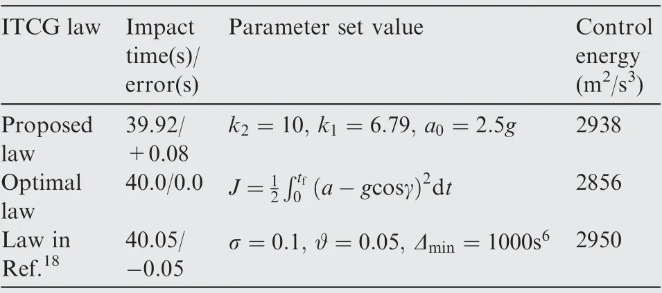
Table 3 Comparison of proposed laws with other guidance laws.
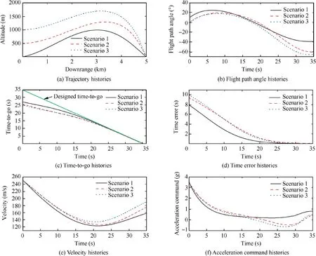
Fig. 6 Simulation results of basic characteristics of proposed law.
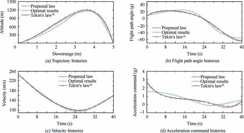
Fig. 7 Simulation results of comparison with other guidance laws.
7. Conclusions
Aimed at the problem of impact time control for missiles with time-varying velocity, this study proposes a biased PNG law established as a form of time-to-go error feedback. To cause the existing time-to-go estimation to adapt to a varying velocity, this study first derives a prediction algorithm of the velocity profile and then uses a third-order polynomial to fit the velocity and replace the constant velocity with the future mean velocity.Three simulations are performed to verify the performance of the proposed law. The first simulation confirms the accuracy of the time-to-go estimation algorithm. The second simulation illustrates that the law can achieve the terminal constraints, and the last simulation shows that the proposed law has a close control energy cost to the optimal results.Although this study has a major limitation with the assumption of small angles, the findings have a number of important implications for future practice and certainly add to our understanding of how to address the velocity variation problem.
Acknowledgement
This study was supported by the Joint Foundation of the Ministry of Education of China (No. 6141A02022340).
Appendix A. Considering that the missile is powered by the
known trust T, which is shown in Fig. A1, Eq. (A1) and Eq.(A2) can be rewritten as

Since α is assumed to be a small angle, Eq. (A2) is approximate to Eq. (1), so the results of Eq. (6) to Eq. (20) are unchanged.
Substituting Eq. (20) into Eq. (A1) gives
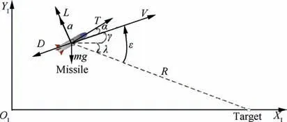
Fig. A1 Homing engagement geometry with thrust.

According to Eq. (A3), there is an addition term of T/m,which can be regarded as a constant, so the solution of Eq.(A3) is similar to Eq. (21).
Then, the following derivation process is the same as the case of unpowered missiles.
 CHINESE JOURNAL OF AERONAUTICS2020年3期
- CHINESE JOURNAL OF AERONAUTICS的其它文章
- Experimental investigation on operating behaviors of loop heat pipe with thermoelectric cooler under acceleration conditions
- Investigation of hot jet on active control of oblique detonation waves
- Experimental study of rotor blades vibration and noise in multistage high pressure compressor and their relevance
- Unsteady wakes-secondary flow interactions in a high-lift low-pressure turbine cascade
- Effect of protrusion amount on gas ingestion of radial rim seal
- Optimization design of chiral hexagonal honeycombs with prescribed elastic properties under large deformation
