Correction method of airfoil thickness effect in hinge moment calculation of a folding wing
Ho XU, Jinglong HAN,*, Hiwei YUN, Xiomo CHEN
a State Key Laboratory of Mechanics and Control of Mechanical Structures, Nanjing University of Aeronautics and Astronautics, Nanjing 210016, China
b Research Institute of Unmanned Aircraft, Nanjing University of Aeronautics and Astronautics, Nanjing 210016, China
KEYWORDS Aerodynamic correction;Dynamics simulation;Flight simulation;Folding wing;Hinge moment;Morphing aircraft
Abstract The influences of airfoil thickness on the aerodynamic loading distribution and the hinge moments of folding wing aircraft are presented in this work. The traditional panel method shows deficiencies in the calculation of folding wing’s hinge moments. Thus, a thickness correction strategy for the aerodynamic model with CFD results is proposed, and an aeroelastic flight simulation platform is constructed based on the secondary development of ADAMS. Based on the platform,the developed aerodynamic model is verified,then the flight-folding process of the folding wing aircraft is simulated,and the influences of airfoil thickness on the results are investigated.Results show that the developed aerodynamic model can effectively describe the thickness effect of the folding wing. Airfoil thickness, which cannot be considered by the panel method, has a great influence on the hinge moments during the folding process,and the thickness correction has great significance in the calculation of folding wing’s hinge moments.
1. Introduction
As a typical morphing aircraft, a folding wing aircraft can change its configuration by folding its wings in flight to fit various flight environments and accomplish multiple missions,and its operational performance is much higher than that of a conventional fixed configuration aircraft.1-3Thus, folding wing aircraft has elicited widespread attention.
Many studies have been conducted on the dynamic response of folding wing aircraft during the folding process.Zhao and Hu4combined the Craig-Bampton synthesis technique with the flexible multi-body dynamic approach to construct a flexible multi-body dynamic model for a folding wing aircraft and verified the correctness of this method by simulating the folding process. Hu et al.5developed a calculation method of Aerodynamic Influence Coefficient (AIC)matrices in the time domain based on the doublet-lattice method, and coupled this approach with the structural model to simulate the aeroelastic response during the folding process of a fuselage-fixed folding wing aircraft. Lee and Weisshaar6treated the morphing process of the folding wing aircraft as a quasi-steady state and used the static trim analysis to calculate the hinge moments at different folding angles based on the ZONA6 aerodynamic model.Reich et al.7,8developed an integrated aeroelastic multi-body morphing simulation tool using the flexible multi-body dynamics method and their in-house vortex lattice code to simulate the morphing process of folding wing aircraft. On the basis of this tool, Scarlett et al.9conducted a series of wind tunnel simulations on folding wing aircraft and researched the changes in load paths and hinge moments under specific motions.
Given the research status, the calculation of the hinge moment, as a representative issue on the folding wing, has attracted extensive attention.Although CFD method can provide an accurate aerodynamic model, the moving grid technique encounters difficulty in handling the wide range of wing motion, and the overlapping grid method cannot fill the ever-increasing gaps between the wings during the folding process that are covered by flexible skin in the actual model.2Technical difficulties remain in simulating the folding process using the CFD method directly. The majority of current studies on this problem applied theoretical aerodynamic models,such as the vortex lattice method, which ignores the thickness of the airfoil in aerodynamic modeling. However, this paper discovered that airfoil thickness tends to influence the aerodynamic loading distribution of the folding wing.Thus,the panel method may be inadequate for the calculation of the folding wing’s hinge moments. Accordingly, a thickness correction method with CFD results is proposed in this work, and an aeroelastic flight simulation platform based on the secondary development of ADAMS is constructed. The developed aerodynamic model is verified with the platform, the flightfolding process of the folding wing aircraft is simulated, and the influences of airfoil thickness on the simulation results are investigated.
2. Simulation platform
2.1. Folding wing aircraft model
A typical folding wing half-model can be treated as a flexible multi-body structure, and each flexible body is a substructure,i.e., the fuselage (I), the inner wing (II), and the outer wing(III) as shown in Fig. 1. Moreover, the trailing edge of the outer wing is equipped with an aileron(IV)to maintain the stability of the flight-folding process. The folding angle θ is defined as the angle between the fuselage and the inner wing.To guarantee the lift performance of folding wing, the outer wing remains parallel to the fuselage during the folding process.
2.2. Correction of the aerodynamic model
2.2.1. Weakness of the panel method
The panel method is an approximation technique based on linearized potential flow theory. It is often used in the aerodynamic modeling of a wing. In the panel method, the lift surface problem can be expressed as a superposition of the angle of attack,camber,and thickness.The panel method considers that the thickness term has no influence on lift and hence can be neglected in aerodynamic modeling. The vortex lattice method, doublet-lattice method, and recently developed unsteady vortex lattice method10all belong to the panel method category. The basic idea is to arrange the basic singularities on the lifting surface,and reduce the problem of solving 3-D flow domain to a surface solving problem. When the flow around the wing is considered, the thickness term is neglected in the panel method,and the singularity source that can simulate the effect of thickness is not arranged.11Panel method can be used in the aerodynamic calculation of conventional fixedwing aircraft and have gained many achievements. However,with the development of aviation technology,new types of aircraft are emerging, which challenges the existing aerodynamic calculation method.
A folding wing morphing aircraft should fold and unfold its wings in flight, and aerodynamic interference occurs between wing surfaces when the folding angle is large. Fig. 2 shows the pressure distribution of a folding wing aircraft with an NACA0006 symmetrical airfoil shape at an angle of attack of 0° and a folding angle of 120° (Mach number=0.3).Low-pressure areas are formed between the fuselage and inner wing, as well as between the inner and outer wings, and affect the distribution of wing surface loads.The distributed aerodynamic forces and corresponding moments tend to affect the dynamic parameters, such as the hinge moment during the folding process.
Low-pressure areas are formed owing to the airflow channel between the fuselage and the inner and outer wings.Owing to airfoil thickness, the middle section of the channel is narrowed, and thus the airflow is accelerated and low-pressure areas form.In the panel method,the influences of airfoil thickness cannot be considered, and the aerodynamic loads of the fuselage and wings are zero.Therefore, the panel method may be inadequate for the calculation of the folding wing’s hinge moments.
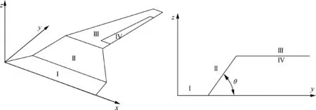
Fig. 1 Sketch of a folding wing.
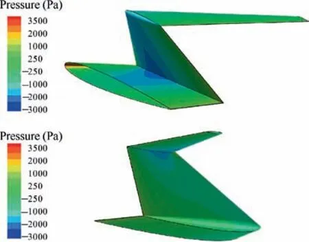
Fig.2 Pressure distribution of folding wing at an angle of attack of 0°.
2.2.2. CFD correction of the aerodynamic model
In the linear range, the airfoil aerodynamic load is a linear superposition of constant and unsteady loads, and the constant pressure distribution is a superposition of the three contributions of the angle of attack, camber, and thickness, as shown in Eq. (1). We believe that airfoil thickness mainly affects the constant part, and the unsteady term Cp,1is not affected. According to the linear superposition principle of the aerodynamic load,only the thickness term Cp,0,cin the constant part should be corrected in the aerodynamic calculation of the folding wing. The thickness term is the steady pressure distribution of the symmetrical airfoil at an angle of attack of 0°. In this work, the CFD method is utilized to calculate the airfoil pressure distribution,then used to correct the thickness term of the aerodynamic model.Detailed correction steps are described in Section 2.3.

where Cp,0is the constant part of the surface pressure coefficient of the aircraft, Cp,0,a, Cp,0,fand Cp,0,care contributions of the angle of attack, camber, and thickness, respectively,and Cp,1is the pressure distribution caused by unsteady motion.
2.3. Simulation platform
To calculate the hinge moments of folding wing during the flight-folding process,an aeroelastic flight simulation platform based on the secondary development of ADAMS is built.Fig.3 shows a brief flowchart of the platform containing three modules, which are multi-body system dynamics modeling,unsteady aerodynamic load modeling, and flight control modeling.
The platform integrates the capabilities of ADAMS and NASTRAN in structural modeling,combining advanced finite element models with multi-body dynamics models to simulate complex flexible multi-body systems. ADAMS allows the incorporation of flexible bodies from finite element analyses through the Craig-Bampton component mode synthesis process.12By using the NASTRAN software, the classical Craig-Bampton modal synthesis method is used to generate modal neutral files suitable for import into the ADAMS modeling environment. Each substructure must be created separately so that ADAMS can treat them as separate parts.After each substructure is imported, it is assembled in ADAMS.The assembled simulation model is shown in Fig.4.
In the aerodynamic modeling, the classical doublet-lattice method is developed by a similar process in Ref. 5, and the AIC matrices in the time domain are derived for the flightfolding process.The flowchart is shown in Fig.5.First,several intermediate configurations are selected, and aerodynamic modeling is performed by the doublet-lattice method for the generation of the AIC matrices Q1k, Q2k,..., Qnkfor the aerodynamic nodes.Next,the interpolation between the aerodynamic and structural nodes is realized by the spline matrix, and the AIC matrices Q1g, Q2g,..., Qng for the structural nodes are obtained. Then the Roger method is used to derive a rational approximation of the AIC matrices in the Laplace domain,and a series of AIC matrices A1, A2,..., Anand E1, E2,...,Enin the time domain for the intermediate configurations can be achieved by transforming the fitting result into time domain. Finally, the interpolation method is used to obtain the aerodynamic influence coefficient matrices Aθand Eθof any folding angle θ.
The AIC matrices developed form the doublet-lattice method can be used to calculate the steady and unsteady aerodynamic loads, including those caused by elastic deformation but not the part caused by airfoil thickness. We conduct a thickness correction for this aerodynamic model. The thickness effect is mainly influenced by the folding angle.The larger the folding angle,the more obvious the thickness effect is;thus,the thickness correction is based on the folding angles. Airfoil pressure coefficient Cp,0,ccaused by airfoil thickness is obtained by calculating the aerodynamic loads of the intermediate configurations at an angle of attack of 0° through the CFD method. The thickness correction factor ciof folding angle θiis achieved by integrating the airfoil pressure and then interpolating to the structural nodes.The unsteady aerodynamic load with thickness correction is provided in Eq.(2).cθis the thickness correction factor of any folding angle θ and is obtained by interpolating the correction factors of several selected intermediate configurations. q∞·cθis the normal aerodynamic load acting on the structural nodes caused by the airfoil thickness,including the components in the y and z directions.The derivation of the formula and specific meanings of the symbols are detailed in Section 2.3.1.

where q∞is the freestream dynamic pressure,b is the reference length, V is the air speed, yiis the state vector related to ug, fgand ugare the aerodynamic force vector and the displacement vector for structural nodes, respectively.
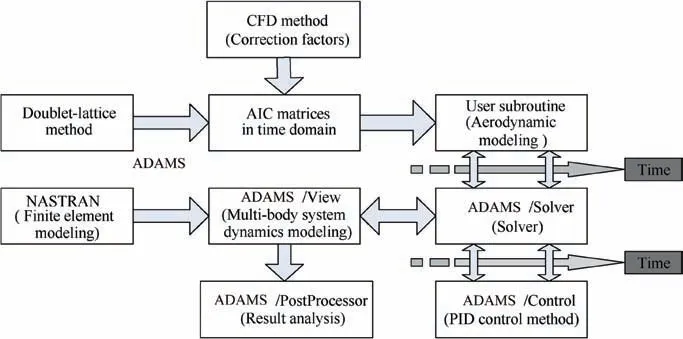
Fig. 3 Aeroelastic flight simulation platform.
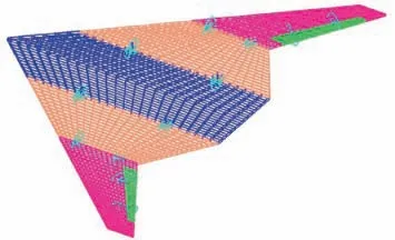
Fig. 4 ADAMS model of folding wing aircraft.

Fig. 5 Aerodynamic modeling process.
Through the secondary development of ADAMS, aerodynamic loading and updating are realized during the folding process. Generalized forces GFORCE are set at structural nodes, and corresponding user subroutine SUBROUTINE GFOSUB are programmed. The process of coupling simulation is shown in Fig.6.The subroutine uses the SYSARY and SYSFNC macros to read the position, velocity, and acceleration information of the structural nodes from the ADAMS Solver and passes them to the aerodynamic calculation program. The aerodynamic load is calculated by the AIC method and fed back to the ADAMS Solver.
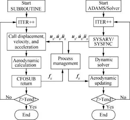
Fig. 6 Process of coupling simulation.
The mass distribution and aerodynamic load distribution of a folding wing change considerably during the folding process.For flight stability during folding, a longitudinal stabilization control system is established in the ADAMS built-in Controls module. The system uses the angle of attack, pitch rate, altitude, and plunging velocity of an aircraft as feedback signals and generates a stabilization control law using the PID control method to drive the aileron deflection and maintain the longitudinal stability of the aircraft.
2.3.1. Derivation of the AIC matrix
The aerodynamic model for the folding wing with a specific fixed folding angle can be formulated by the doublet-lattice method13as

where Qkis the AIC matrix for the aerodynamic nodes,Ma is the Mach number,ω is the reduced frequency,fkand ukare the aerodynamic force vector and the displacement vector for aerodynamic nodes, respectively (for a folding wing, contain components in both directions of y and z axes).
The interpolation between the aerodynamic and structural nodes can be achieved by applying spline matrix Gkg.14,15The AIC matrix for the structural nodes is obtained as

The relationship between aerodynamic forces and displacements of structural nodes can be expressed as


The Roger fitting16is used to derive a rational approximation of the AIC matrices in Laplace domain, which can be expressed as where s is the Laplace variable, A and E are undetermined matrices, and riis the undetermined coefficients. The n values in the range of reduced frequency ranges of interest are taken as ri, and n is taken as 4 for a general fitting accuracy requirement.
The fitted AIC matrix Qg(s ) is converted to the time domain, and the aerodynamic force fgof the structural nodes can be expressed as

For y in Eq. (7), the following relationship exists:

3. Numerical examples
The geometry and dimensions of the folding wing in the present study are shown in Fig. 7. The fuselage and wings are composed of skin and inner skeleton and assume an NACA0006 airfoil shape. An aileron is set at 20% of outerwing chord and 11%-83% of the outer wing span;6it serves as a control surface during the flight-folding process. These substructures are made of aluminum and connected by rotating hinges, as indicated by the circles in Fig. 7(c). Counterweights are added to the fuselage and wings to represent the weight of the engine,actuators,and transmissions,as indicated by the triangles in the figure. The main parameters of the simulation model are listed in Table 1.The typical simulation conditions in this study are 2 km flight altitude and 0.3 flight Mach number.
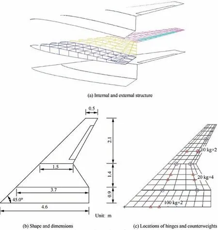
Fig. 7 Geometries and dimensions of the folding wing aircraft.

Table 1 Main parameters of aircraft.
3.1. Correction and verification of aerodynamic model
According to Section 2,the panel method treats the lift surface problem as a superposition of the angle of attack,camber,and thickness. In general aerodynamic modeling of a wing, the panel method considers that the thickness term has no influence on lift and can be neglected. This has been proven to be insufficient in the calculation of a folding wing’s hinge moments.Hence,we proposed to use the CFD method to calculate the thickness term, and then correct the existing panel method.The thickness term is the pressure distribution of symmetric wing with non-zero thickness at zero angle of attack.Besides, the larger the folding angle, the more obvious the thickness effect is. Thus, the CFD-based aerodynamic thickness correction is based on different folding angles, wherein the folded wing is meshed every 15°folding angle.Fig.8 shows the wall mesh of the folded wing at 120° folding angle. The structured mesh is used and the total number of hexahedra cells is approximately 1.4 million. The flow around the wing is simulated with Fluent solving Euler equations.
CFD solution is performed for symmetric wing at an angle of attack of 0° and every 15° folding angle to obtain the pressure distribution caused by thickness. The airfoil pressure caused by the thickness of the 120° folding angle is shown in Fig. 2. Obvious low-pressure areas are formed between the fuselage and inner wing,as well as between the inner and outer wings.Fig.9 shows the normal aerodynamic loads of the inner and outer wings caused by the low-pressure areas.Fig.10 presents the changes in the loads with the folding angle. The changes show that the strength of low-pressure area I is significantly higher than that of low-pressure area II.With the folding of the wings, the strength of the two low-pressure areas increases. When the folding angle is greater than 90°, the left and right inner wings are close to each other, which greatly enhances the strength of low-pressure area I,thereby resulting in a significant increase in the normal aerodynamic load of the inner wing.
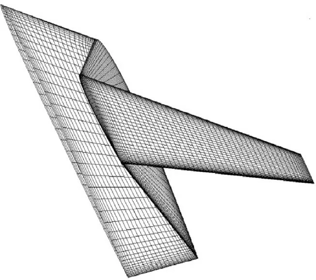
Fig. 8 Wall mesh of 120° folding angle.
The thickness correction factor ciis obtained by integrating and interpolating the airfoil pressure caused by thickness, and then used for the correction of the aerodynamic model. An aerodynamic comparison of pre-correction (angle of attack and camber issues calculated by the panel method), postcorrection (angle of attack and camber issues calculated by the panel method integrated with thickness issue calculated by the CFD method), and direct CFD (angle of attack, camber,and thickness issues calculated by the CFD method)calculation results is shown in Fig. 11. The aerodynamic moments about the hinges under 1 g normal acceleration were calculated in the comparison.
The calculation results of the aerodynamic moments before and after correction vary greatly. The post-correction aerodynamic moment of the inner wing is smaller than the precorrection result when the folding angle is less than approximately 90° and larger than the pre-correction result when the folding angle is greater than 90°. The post-correction aerodynamic moment of the outer wing is smaller during the entire folding process.The main reason is that when the folding angle is small, the force arm of F2to the inner wing hinges is larger than that of F1. At this time, the influence of F2dominates although F1is larger, and reduces the aerodynamic moment of the inner wing, thus decreasing the post-correction result.With the folding of the wings,the force arm of F2to the inner wing hinges decreases continuously, and when the folding angle increases to a certain level,the influence of F1dominates and increases the aerodynamic moment of the inner wing.When the folding angle is close to 120°,the left and right inner wings are close to each other, which greatly enhances lowpressure area I and significantly increases the post-correction result.Meanwhile,the aerodynamic moment of the outer wing is mainly affected by F2and diminishes throughout the folding process.As the folding angle increases,the strength of the lowpressure area II is continuously increased,resulting in an everincreasing difference in the outer wing’s simulation results before and after the correction. In the fully folded configuration, the calculation errors (before and after correction) of the aerodynamic moments of the inner and outer wings reach 32% and 22%, respectively.
In addition, the direct CFD calculation results agree well with the post-correction results, and the error is less than 4%, which shows the effectiveness of the modified aerodynamic model. The panel method (angle of attack and camber issues)plus CFD correction(thickness issue)is consistent with the direct CFD method (angle of attack, camber, and thickness), indicating that the calculation results of the angle of attack and camber issues by the panel method and CFD method are consistent, which is also a mutual verification of the calculation results of the panel and CFD methods.

Fig. 9 Aerodynamic loads caused by low-pressure areas.

Fig. 10 Changes in normal aerodynamic loads with folding angle.

Fig. 11 Comparison of the aerodynamic moments (1 g normal acceleration).
The above comparison shows the difference between the aerodynamic models before and after the correction and verifies the reliability of the modified model.Notably,although the CFD method can be directly used in calculating the fixed configuration to verify the modified aerodynamic model, this method is difficult to use directly in the simulation of the folding process.Thus,the direct CFD method is not applied in this study,but a thickness correction based on the panel method is performed.
3.2. Simulation of flight-folding process
The influence of airfoil thickness on the aerodynamic load has been discussed. This section discusses the effect of the thickness on the hinge moments of the folding wing by simulating the flight-folding process. The folding process starts at the equilibrium state of the unfolded wing configuration. Hence,the preliminary trimming needs to be completed first. With the flight simulation capability of the platform,the initial equilibrium of the aircraft can be reached by a flight control process.
In the simulation, the aircraft is designed to maintain an unfolded wing configuration at the initial 10 s for the preliminary trimming calculations,and the wings begin to fold at 10 s.When the wings are folded in place, the aircraft retains a folded configuration to maintain a 1 g level flight.
The general variation of the dynamic parameters of the aircraft during the flight-folding process is first investigated, followed the influence of airfoil thickness on the simulation results. The folding process with a folding time of 30 s is simulated using a corrected aerodynamic model. The main dynamic parameters of the aircraft are shown in Fig. 12.
The figures show that the initial 10 s is used for preliminary trimming. Moreover, the initial angle of attack and deflection angle of the aileron are zero, and the lift is not enough to balance gravity, resulting in a sharp drop of altitude. By controlling the ailerons to deflect upward, a head-up torque is generated, increasing the angle of attack to produce substantial lift to balance gravity. Through the flight control, the aircraft reaches the initial equilibrium state at about 5 s. The initial trimmed angle of attack is 1.44°,and the deflection angle of the aileron is-0.15°.The wings begin to fold at 10 s.As the folding angle increases, the effective wing area decreases, and the aircraft drops.To maintain a longitudinal balance,ailerons are designed to deflect upward, producing a head-up torque that can increase the angle of attack and maintain lift. The wings are folded in place at 40 s followed by a slight overshoot.After about 5 s, the aircraft is stabilized to a new equilibrium state, which is the trimmed condition of the folded wing configuration. Compared with the unfolded wing configuration,the angle of attack increases to 5.38°, and the ailerons deflect upward to -4.74°.
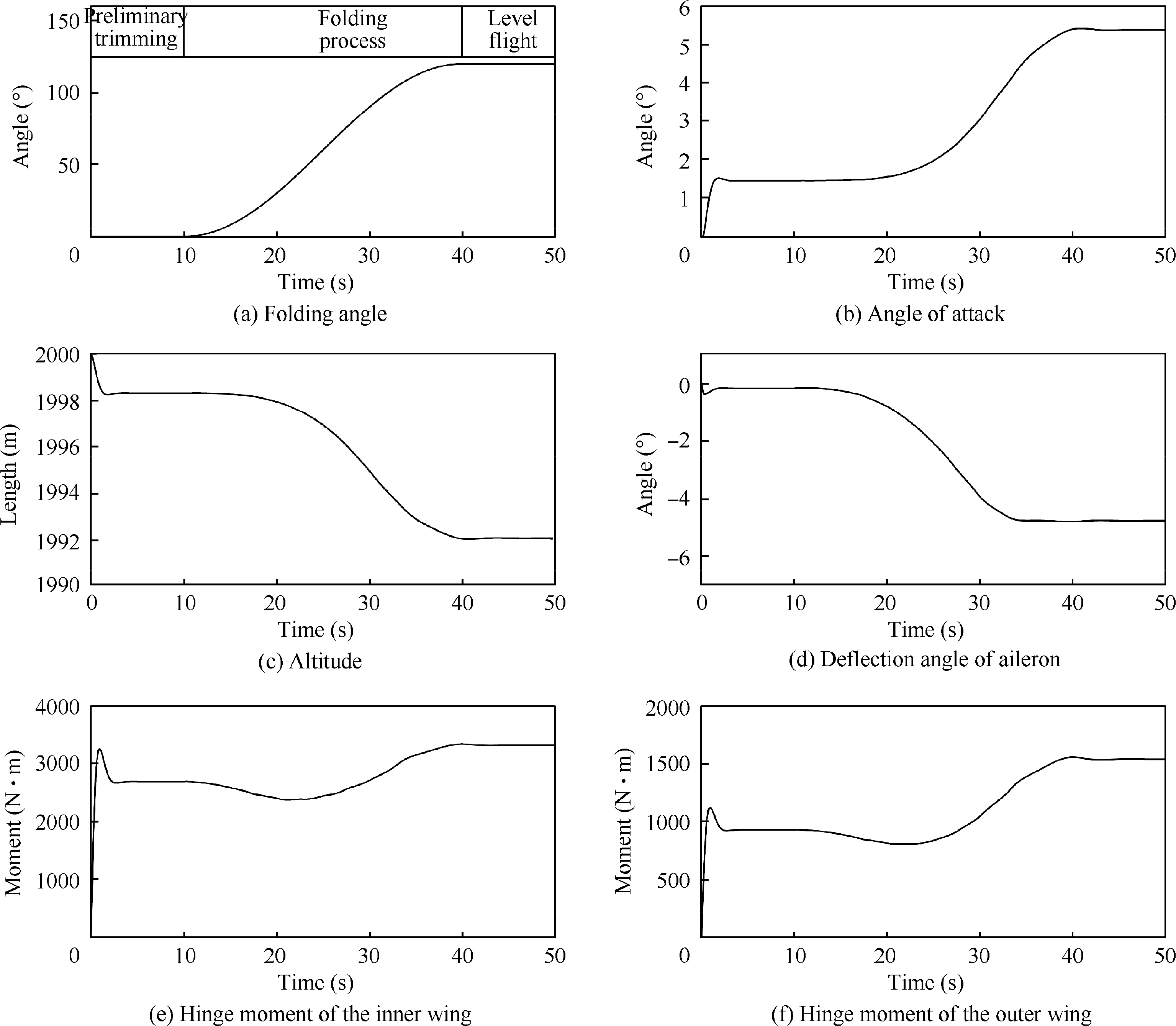
Fig. 12 Dynamic response during flight-folding process.
The change in hinge moments during the folding process is considered.In the initial unfolded state,the driver of the inner wing must drive the inner and outer wings to move together,and the hinge moment in this state is relatively large at 2697 N·m, whereas the hinge moment of the outer wing is relatively small at 931 N·m.With the folding of the wings,several important changes occur in the aerodynamic force that acts on the wings.First,the arm of the aerodynamic force that acts on the outer wing to the inner wing hinges is reduced,thereby also decreasing the hinge moment of the inner wing. Second, the aerodynamic force that acts on the outer wing increases with the angle of attack, thus also increasing the hinge moment of the inner wing. Third, the thickness effect of the airfoil increases and affects the hinge moment of the inner and outer wings. And considering the changes in inertia load and mass distribution during the folding process, the changes in hinge moments become highly complicated. Platform simulation results display that the hinge moments of the inner and outer wings tend to decrease first and then increase. When folded in place, the hinge moments of the inner and outer wings increase to 3328 and 1542 N·m, respectively.
3.3. Influence of airfoil thickness
Fig.13 shows the dynamic response during the folding process before and after the aerodynamic correction. The solid line is the simulation result with a thickness correction, and the dashed line is the result of the uncorrected panel method.The comparison shows that consistent with the results of the aerodynamic moments in Fig. 11, the post-correction hinge moment of the inner wing is smaller than the pre-correction result in the first half of folding and larger in the second half and reaches a maximum difference of 988 N·m when the wings are folded in place. The post-correction hinge moment of the outer wing is smaller during the entire folding process and reaches a maximum difference of 649 N·m when folded in place.The comparison results show the influence of the airfoil thickness on the hinge moments of the folding wing during the folding process and illustrate the necessity of thickness correction in the aerodynamic calculation.
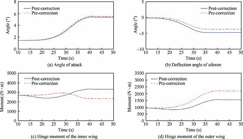
Fig. 13 Dynamic response before and after thickness correction.
The influence of airfoil thickness on the hinge moments of folding wing is discussed above.Owing to airfoil thickness,the aerodynamic loading distribution of wing surfaces and the hinge moments during the folding process are affected. This thickness effect is influenced by airfoil thickness and flight Mach number. Several typical working conditions were selected and the flight folding process was simulated.The simulation results of the hinge moments are shown in Fig.14.The top two figures show the changes in the hinge moment of the folding wing with different airfoil thicknesses, and the solid line is the pre-correction results without considering airfoil thickness. The two figures below show the results with different Mach numbers, where the simulation condition of precorrection is 0.3 Ma (in the low Mach number range, the results calculated by the panel method almost do not change with the Mach number).The post-correction results show that as the thickness and Mach number increase, the hinge moments of the inner and outer wings change considerably,while the pre-correction results cannot reflect this change and the simulation errors before and after the correction increase.
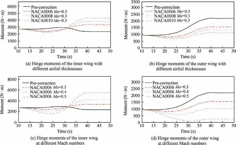
Fig. 14 Hinge moments under different working conditions.
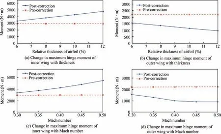
Fig. 15 Changes in hinge moments with thickness and Mach number.
Fig. 15 shows that maximum hinge moment changes with the airfoil thickness and Mach number. The solid line is the simulation result after a thickness correction, and the dashed line is the result before the correction. The pre-correction results show that the maximum hinge moments calculated by the panel method is hardly affected by the thickness and Mach number. The post-correction results show that the maximum hinge moments of the inner and outer wings show a tendency of linear variation with the increase of thickness and Mach number. The maximum hinge moment of the inner wing presents a trend of linear increase, whereas the outer wing shows a decreasing trend.However,when the Mach number increases up to about 0.4,the maximum hinge moment of the outer wing shows a pattern of nonlinear variation. This is mainly because the maximum hinge moment of the outer wing occurs in the folded state when the Mach number is smaller than 0.4 and in the initial extended state when the Mach number is larger than 0.4 (see Fig. 14). The airfoil has no thickness effect in the initial extended state. Therefore, the maximum hinge moment of the outer wing does not decrease when the Mach number is increased to a certain level.
4. Conclusions
(1) Airfoil thickness significantly influences the aerodynamic loading distribution of folding wing aircraft,and the traditional panel method is inadequate for the calculation of a folding wing’s hinge moments.
(2) A thickness correction with the CFD results is proposed,and an aeroelastic flight simulation platform is constructed based on ADAMS.
(3) The numerical results show that airfoil thickness has a great influence on the hinge moments of a folding wing,and the thickness correction of aerodynamic model is significant.
Acknowledgements
This study was co-supported by a Project Funded by the Priority Academic Program Development of Jiangsu Higher Education Institutions and the National Natural Science Foundation of China (No. 11472133).
 CHINESE JOURNAL OF AERONAUTICS2020年3期
- CHINESE JOURNAL OF AERONAUTICS的其它文章
- Experimental investigation on operating behaviors of loop heat pipe with thermoelectric cooler under acceleration conditions
- Investigation of hot jet on active control of oblique detonation waves
- Experimental study of rotor blades vibration and noise in multistage high pressure compressor and their relevance
- Unsteady wakes-secondary flow interactions in a high-lift low-pressure turbine cascade
- Effect of protrusion amount on gas ingestion of radial rim seal
- Optimization design of chiral hexagonal honeycombs with prescribed elastic properties under large deformation
